Dynamax SapIP-IRT User manual

SapIP-IRT
Dynamax, Inc
SapIP-IRT
Instruction Manual
This manual provides Dynamax customers with a detailed collection of instructions on
How to set-up, collect data and make full application of the SapIP-IRT sensor.
Created: 12/14/2017
Version 8.4
8.4 –Changes from 8.3:
Added quick start guide 1.3, pg 15.
Drip loop on power wire Sec 4, pg 22.
Changed wiring for SDI-12, better cable and color code Sec 4.3, pg 24.

SapIP –IRT Instruction Manual 1/23/2017
Page 1
Dynamax, Inc.
Table of Contents
Topic
I.
Introduction
II.
General Specifications
III.
Assembly and Mounting
Procedures
IV.
Sequential and Functional
Descriptions
V.
Updating Logging Interval
Using XCTU
VI.
FAQs –Frequently Asked
Questions
VII.
Troubleshooting
VIII.
Appendix A: Data Output
Packets

SapIP –IRT Instruction Manual 1/23/2017
Page 2
Dynamax, Inc.
I. Introduction
The new SapIP-IRT wireless infrared temperature system is the latest development in infrared leaf
temperature sensing technology for applications in irrigation scheduling and plant stress detection. As a
temperature sensor, the module has many other applications and can be considered a general purpose
temperature sensor.
The newest IRT( Infra-Red Temperature) module has a narrow field of aperture and has an imbedded
processor temperature controller for a calibrated digital signal. The imbedded processor provides a comparison
to the reference body temperature and makes a series of readings to generate one value. This module has a
very accurate reading to +/- 0.5 C, is very stable over time, and has a signal window and field of view (FOV)
For example; at a 20 degrees FOV one would have a complete coverage of 95%. So, for a 1 meter wide
target, a customer would have to place his or her IRT 3 meters above the item or surface being measured (20
degrees FOV).
This new system allows small IRT nodes to be distributed throughout a field, and for its recorded data
to be collected with a coordinator module then stored in a logger or transmitted to a display or controller.
There are several means of collecting the IRT’s temperature node data: communicating in a public
ZIGBEE data network, or with a serial port or by analog voltage signals. There are three versions:
SAPIP-IRT
Zigbee Node
Digital Data Stream
Wireless Transmission to Zigbee coordinators
SAPIP-IRT-AD
Analog Module –
Volts Output
Wired connect to SAPIP-RS9, or SAPIP-RS24
Or any analog logger.
SAPIP-IRT-SD
Serial 3 wire
Digital Data Stream
Wired transmission to loggers and SDI-12 field
bus. (New product 4 Q 2016)
The following items support the ZigBee wireless version:
SAPIP-IRT-COR
Coordinator module
Central termination for ZigBee,
collects data and transfers to a USB
port
SAPIP-REP24-ZB
Router module
Repeater/Router to extend range of
ZigBee networks
SPIP-IRT-WS
Software application
Simple data collection program using
the coordinator module
Once it is transmitted the data can be calculated, displayed, and graphed on Dynamax’s customer
website named Agrisensors.net. This network will consist of the customer’s SapIP network, along with the
units accompanying temperature (analog) sensors.

SapIP –IRT Instruction Manual 1/23/2017
Page 3
Dynamax, Inc.
The client also has the option to download his or her data files to a PC or an imbedded SCADA
controller. PC data collection is supported with the purchase of a coordinator module (SAPIP-IRT-COR ) and
a windows software collection program, the IRT Watcher, (SPIP-IRT-WS). These data sets can be imbedded
into SCADA or independent controllers to calculate plant stress models which can determine when and how
often the client’s crops need irrigation. Dynamax does not plan to provide SCADA controllers, but does
provide stress monitoring hardware and a WIFI broadcast manager, the SPIP-SALH –The Stress Accumulator
Logger.
Further, the SapIP-IRT leaf temperature sensors can integrate as a complete stand-alone system or as
part of a SapIP wireless mesh network. The complete network contains an option for plant sap flow, sap
velocity, soil moisture, weather, and leaf temperature, all which can be monitored simultaneously all in one
system. Up to 40 SapIP-IRT nodes can be connected wirelessly with a single GSM modem and the nodes can
be “daisy-chained” up to four levels deep, which can allow data to be transmitted from distances over a mile
away.
Lastly, these SapIP systems are both versatile and flexible allowing them to be applied for several
different purposes.. Each unit is configurable for a customer’s specific applications, and records surface
temperature from 0-50 C. The sensor operates over a long distance via the relay and coordinator network
covering a very large field as shown in the chart Figure 1. The IRT may be arranged in a pivot system, where
the data is transmitted to a central pivot controller (Figure 2). The structure of the IRT network is a mesh
network so nodes can relay data from the End node to a Coordinator node. Each Coordinator node is the
collection point for all data, and therefore is the concentrator for all data coming to the system. Each Router
has a limit of 10 Zigbee nodes. Each Router reports its data to the Coordinator, which dumps its data into the
IRT Watcher, the Windows program that creates and saves data to a PC. Each node arranges communication
links upon power-up finding the shortest path to the Coordinator node.

SapIP –IRT Instruction Manual 1/23/2017
Page 4
Dynamax, Inc.
Figure 1: IRT temperature monitor over a large field reporting to a network of Zigbee Routers
Figure 2: IRT on a Pivot Arm, Reporting to a Central Controller

SapIP –IRT Instruction Manual 1/23/2017
Page 5
Dynamax, Inc.

SapIP –IRT Instruction Manual 1/23/2017
Page 6
Dynamax, Inc.

SapIP –IRT Instruction Manual 1/23/2017
Page 7
Dynamax, Inc.
II. General Specifications
1. Infrared Temperature Sensor Specifications
1.1 Purpose
-The imbedded infrared temperature sensor reads an object’s temperature as well as its own body
temperature and compensates for the body temperature.
1.2 Specifications
-Industrial/commercial accuracy: +/- 0.5 ˚C (0-50 degrees C).
-Each unit is factory calibrated and very stable over time. (Ref USDA internal report)
-Narrow field view:
o10 Degrees (50% sensitivity) (5.6:1 View Dist:Width)
o15 Degrees for 80% sensitivity
i.e. at 15 degrees 80 % of the temp signal is included in view.
(4:1 View Dist:Width)
o20 Degrees for 95% sensitivity
i.e. at 20 degrees 95% of the temp signal is included in view.
(3:1 View Dist:Width)
2. Data
2.1 Purpose
-The purpose of the SapIP-IRT’s data collection is to provide the user with real time data
measurements. Typically the sensor will take 2 seconds to read the temp, and then the results are
either averaged or saved according to the collection steps.
-
-Each set of data can be displayed in a digital format for when it is accessed wirelessly and
presented remotely in graphical format for crop temperature and stress analysis.
-
-Analog data will be converted to digital data and presented in crop temperature and stress analysis
calculations. Since analog data is converted from digital and then converted back to digital, it is
inherently less accurate than digital and yet is very similar to non-IR rated temperature sensors.

SapIP –IRT Instruction Manual 1/23/2017
Page 8
Dynamax, Inc.
2.2 SAPIP-IRT Specifications
2.2.1 Data Collection –RF Network
-Samples are taken continuously every 10 seconds, accumulated and then averaged. This
average value is then sent by radio at 1, 5, 10, 15, 30 or 60 minute intervals. The averaging
accumulator is then reset.
-Settings are defined upon order from Dynamax. These settings are normally set in the factory,
but are changeable in the field using the IRT watcher program.
Protocol:
-Open Protocol: Data can be encrypted, coded, and read by any manufactured Zigbee device or
gateway.
-The Dynamax preferred network is the Digi International Zigbee network.
-
-Adjacent Zigbee networks have settings for their respective network ID’s to discriminate
different signals.
oNotes on Open: We have found that a variety of manufacturers have implemented the
“open” Zigbee protocol, however that does not mean that each will find the specific
node you may purchase without programming. For example a Texas Instruments (TI)
Zigbee may be quite difficult to program to talk to a Digi device, since the TI device
may need a significant development tool to program it to accept a setting we have
chosen for the Digi Device.
-In our Zigbee Format: We have chosen the Digi International since the tools, and supporting
coordinator hardware is complete and fully supported with Windows software tools. Settings
for the groups of agricultural networks that are close together requiring Pan and in some cases
channel assignments to avoid interruption. Our application engineers and technicians are very
familiar and can program your network to satisfy any requirement.
2.2.2 Output
-Sensor output is a packet transmission which contains a time tick, serial number, battery voltage
target IR temperature (+/- 0.01 degrees Celsius resolution), and sensor body temperature. Each
item is separated by a comma and the last character is a carriage return. i.e. “1, 17, 5.1, +32.70,
+24.80/cr”
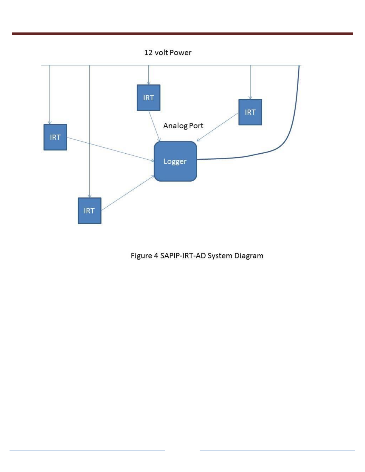
2.3SAPIP-IRT-AD analog specifications
2.3.1 Data Collection Analog output
-Samples are taken continuously every 10 seconds, accumulated then averaged. This average
value is then updated on the analog output port at 1, 5, 10, 15, 30 or 60 minute intervals. The
averaging accumulator is then reset.
-Settings are defined upon order from Dynamax. These settings are normally set in the factory,
but are changeable in the field using the IRT watcher program.

SapIP –IRT Instruction Manual 1/23/2017
Page 9
Dynamax, Inc.
2.3.2 Analog Output Specification
A low impedance voltage scaled to represent temperature is available on the connection wiring
harness. In the equation below, Vo is that output voltage which corresponds to T the target object
temperature.
T = Vo/0.01 - 40.0 (T is in degrees C).
Voltage
Range 0 –1.6 V
2.4SAPIP_IRT-SDI serial digital specifications
The SDI version is a passive client, no actions are performed automatically. Commands and data are transmitted
through a bi-directional serial port. The port follows the standard “SDI-12 A Serial-Digital Interface Standard For
Microprocessor-Based Sensors Version 1.3”. Digital signals are on the wiring harness.
2.4.1 Data Collection
Measurement collection is triggered by an “aM” or “aMC” command. The “a” is the unit address, the “C” calls for a
checksum. The measurement takes 2 seconds.
2.4.2 Serial Data Output
The data is held in memory and transmitted on the port after receipt of a “xD0” command. The response will be the
Sensor ID, then battery voltage, and then object temperature followed by the ambient temperature in one line,
terminated with a carriage return/linefeed. For example: “1+0036+6.0+22.04+21.34(CRLF)”. For the checksum
version a three character checksum comes before the CRLF.
3. Radio Mesh –Wireless Network to Controller, and Network to Cloud Option
3.1 Purpose
-The purpose of the Zigbee protocol is to have a method of connecting the data results from nodes
to a coordinator. The coordinator then concentrates all the data for the industrial controller, or PC
to analyze the data. Users or the central controller make irrigation decisions based on the
information recorded.
3.2 Specifications
-Zigbee Protocol: Ultra-modern, self-healing mesh networking. Contains assignable network PAN
ID’s for comingled networks. Nodes are automatically discovered and assigned a data destination
to the coordinator of the network. The Routers collect data from End nodes and transmit to the
Coordinators assigned to a network.
3.3 Digimesh Range (SapIP-IRT-DM Network)
-900 MHz Range (To be announced in 2016): 6500 feet (2 kilometers).
oThis new Node will have the advanced Digimesh network built –in and extends the range to
4-5x of the Zigbee. The node will have the radio transmit toa gateway protocol that will
extend the data to the Agrisensors.net cloud based monitoring service.
Note: 2 kilometer (1 to 2 miles) These ranges only apply when there is a direct line
of sight (LOS) which is not obstructed and the antenna is correctly aligned. Note
that a high gain antenna requires alignment vertically, so that a very narrow
horizontal aperture lines up with the target antenna.

SapIP –IRT Instruction Manual 1/23/2017
Page 10
Dynamax, Inc.
3.4 Digimesh Range with Analog Signal SapIP-IRT-AD (SapIP- Agrisensors Network)
3.4.1 With the Digimesh SapIP-Network, one may attach 6 IRT-AD sensors to one network node.
3.4.2 Each analog signal node is converted to digital, transmitted, and individually converted to
temperature at the Agrisensor.net customer Ranch Page.
3.4.3 Canopy temperatures may also be converted to Growing degree days, Crop Water Stress
Index (CWSI) , or to Degrees Above Non Stressed Plants (DANS). CWSI requires a SapIP
weather node. The canopy temperature and tree trunk is converted to chill hours and are
best used for freeze warnings.
4. Antenna Range
4.1 Zigbee Specifications 2.4 GHz Range. Dynamax uses a high power 2.4 transmitter.
4.1.1 Range 1600 feet (500 meters): 5 to 7 dBi antenna omnidirectional - (high gain). High gain
antennas are included with coordinators and Routers. Each high gain antenna is sealed form
water and is more sensitive when it’s raining. Part Number kit is SPIP-ACC24-EW.
4.1.2 Range 300-500 ft ( 100-150 meters): 7 dbi antenna omnidirectional –with spark gap
protection, and grounding. Part no is SPIP-ACC24, and is an exposed antenna.
4.1.3 Range 150 feet (50 meters): 1 to 1.5 dBi antenna omnidirectional - (low gain, rubber duck
style). Sealed water-proof rubber duck are supplied by Dynamax (Most Wi-Fi antennas are
not water proof). Part no is SPIP-IRTANT24.
4.1.4 Range over 500 meters: Dynamax supplies directional antennas, which can extend range 3-
4x.
4.1.5 All Ranges are in clear air - line of sight (LOS). With vegetation, the signal should be 1-2
meters above the canopy (3-6 ft). Rain and wet canopy absorb 2.4 Ghz signals, and the
signal is absorbed on a wet antenna. For increased LOS range use the DigiMesh 900 Mhz.
See Section 3.3 or 3.4 for high range.
5. Power SAPIP-IRT-ZB Battery and Solar Panel
5.1 Battery Specifications –
Rechargeable 4 NIMH batteries included. Typical current 2000 mAh, 4.8 V.
(Typical battery pack is 4.8 V nominal, 5.2 V operational charged)
Maximum battery voltage –6.2 V during charging
Minimum battery operations –4.2 V
Operational measurements and response suspended at below 3.8V,
Until minimum voltage is restored (4.2 V).
Only battery recharge will occur below 3.8 V.

SapIP –IRT Instruction Manual 1/23/2017
Page 11
Dynamax, Inc.
5.2 Solar panel or DC adapter for recharge.
DC Adapter –requires 100 mA at 12 V. Top-off mode requires 230mA at 12 volt.
Solar 2 W (150 mA) to 5 Watt solar panel. (Most 5 W solar panels are less expensive.)
Low charge rates to minimize battery temperature.
40 mA charge current (12V), to restore batteries from a 12 V solar panel.
Top off charge is also controlled (see from external commands in ‘IRT Watcher’).
230 mA current (12 V), allowed to charge batteries 5 hours internally, or temperature rise of
the battery, or up to 6.2 V whichever occurs first.
Reverts to low charge rate after above.
Notes:
Any reverse voltages, over voltages and/or voltage spikes are protected at inputs with
resettable fuses.
The IRT battery should not be discharged.
Batteries should be charged before storing.
Batteries should be disconnected before storing.
6 Power SPIP-IRT-AD Analog Version Specifications –
No batteries included.
Logger provides power: DC from either 5 V or 12 V supply to the IRT.
Logger typically switches on IRT for 2 seconds, takes a reading then stores the results. After, the
logger will power down the IRT.
Minimum 5 V input (this is considered typical operation).
Current 6 mA average, maximum 25 mA during readings.
Maximum 12-18 V –voltage or switched supply at 12 V battery nominal.
Current 3 mA average, maximum 12 mA.
7 Power SPIP-IRT-SDI SDI 12 Digital version Specifications
No batteries included.
Logger typically switches on IRT for 2 seconds, then initiates a sequence to alert the IRT to wake up,
then command it to send the serial SDI-12 data, and stores results. Afterward, the logger has the
ability to power down the IRT if it chooses.
Maximum 12-18 V –voltage or switched supply at 12 V battery nominal.
Current 4.5 mA minimum, maximum 5.8 mA during readings.
Input Volts
Current (Avg.)
12.0 V Standard SDI-12
4.6 mA
6.0 V
4.6 mA
5.5 V –Minimum Operation
6.0 mA
8. Enclosure
8.1 Specifications
Completely sealed off field enclosure.
Sealed to IP67, waterproof, rain proof, and weather tightened.
Mounting options include a low-cost 2” EPS conduit hanger
Optional gimbal mounted into a threaded socket (1/4” camera).

SapIP –IRT Instruction Manual 1/23/2017
Page 12
Dynamax, Inc.
#1
#2
III. Assembly and Mounting Procedures
-Each SapIP-IRT should be assembled and installed following the protocol found in the following
sections. This will ensure no problems will arise during each unit’s tenure in the field. A collection of
four separate mounting procedures have been collected and illustrated below.
oSeveral tools will be required during installation. A general set that will be needed are found
here:
Flat-head Screwdriver, (5/64”)
Philips-head Screwdriver
Crescent Wrench or set of
Pliers
Drill /Drill-bit (5/16”)
1. Dynamax Mounting Kits
-The Dynamax Mounting Kit and the Adjustable Mounting Kit are the overall preferred method of
installing each SapIP-IRT unit. Each set of equipment and the procedures for its installation are
described within its associated sub-section(s) below. For lower canopy crop such as cotton or wheat, a
fixed height (3 ft) above ground are recommended.
Materials
-When purchased, both the SapIP-IRT and Adjustable Mounting Kit come with the materials
necessary for proper installation. Each accessory needed during the installation process is included.
1.1 Dynamax SapIP-IRT Fixed
-Dynamax SapIP-IRT
-Each device ordered comes with the 2” EPS conduit hanger
(shown below) to fasten the unit to the mounting kit.
Included are
-¼ ” x 1-1/2”Hex-Head Bolt SS, nut and washer
-5/16 ” x 3” Hex head Bolt, Galv, Nut, and Washer
-Zip-ties (customer provided - optional)
oCan be used to fasten any loose cables to the sensor
cross-arm.
1.1.1 Install the EPS hanger on a vertical pole that has been pre-
drilled with a 5/16” (8mm) hole at the top of a conduit
(1.25” diameter) or a horizontal hurricane fence pipe (1.25”
diameter).
1.1.2 Insert the 5/16 x3 bolt and washer through the EPS hanger
hole and affix to the vertical pipe as shown in #1. Tighten
the lock washer and the nut to hold the IRT in a 45 degree
tilt to the canopy being monitored.
1.1.3 Insert SapIP in the hanger bracket, and insert the ¼ x 1-1/2
Hex Bolt at position #2. Position the IRT and clamp the
hanger so that it is balanced, and add the lock washer and
nut and tighten.
1.1.4 The pole can be inserted into the ground or onto a barbed
wire post or fence post for both fixed and adjustable height.

SapIP –IRT Instruction Manual 1/23/2017
Page 13
Dynamax, Inc.
#2
#1
See Section 2 and 3 of the installation instruction.
1.2 Dynamax Adjustable Mounting Kit
-CM204-D ( See Fig 1 )
oStainless steel sensor cross-arm
oMounting plate
oRequired fixtures
-User provides a 4 ft. Vertical Pipe (1”), and a reducer
2”-1” and a 2” pipe to install into the ground. (See #2)
1.2.1 Installation
-The next section illustrates the procedures Dynamax
recommends when installing the adjustable mounting kit
and how to correctly fasten the SapIP-IRT to the unit.
1.2.2 Assembling the Mounting Kit
-The first objective is to correctly attach the 4 ft. vertical pipe to the mounting plate. To begin,
one will need to determine where he
or she wishes to place the mounting
plate.
-Next, press the plate at the pre-
determined location and locate the
U-shaped bolts and their associated
screws (illustrated in red,(#1) below). The plate should fit securely within the vertical groove
or tract (illustrated in black, (#2) below).
-
oNote: This unit will come with 4 total U-bolts
which will fit around each pipe, either vertically
OR horizontally.
-Place the U-bolts around the pipe and
through the holes of the plate. This
attachment should fit very securely.
-Place a washer on each side of both bolts.
#1
#2

SapIP –IRT Instruction Manual 1/23/2017
Page 14
Dynamax, Inc.
Screw the nuts tightly on top of the washers on each side of both bolts, until the plate is firmly
fastened to the plate. Make sure each U-bolt’s evenly fastens the pipe in place.
oNote: The vertical groove that the pipe fits in should keep the plate and 4 ft. pipe firmly
attached while in the field.
-One now needs to place the sensor cross-arm on the
opposite side of the mounting plate (perpendicular to the
vertical pipe). Begin by locating the last two U-bolts and
their associated washers/nuts.
-Using the same process used to fasten the vertical pipe,
start by placing a washer on each side of both bolts. Screw
the nuts tightly on top of the washers on each side of both bolts, until the plate is firmly
fastened to the plate. Make sure each U-bolts evenly fasten the pipe in place.
-The final mounting kit should look
somewhat identical to figure 5,
illustrated below:
1.2.3 Mounting the SapIP-IRT
-The first objective towards correctly
fastening the SapIP-IRT to the
adjustable mounting kit is to locate a
place on the pipe where one wishes to
mount the IRT.
-If not done so already, one will need to
drill a hole through the pipe center
using a 5/16”drill bit. Position the sensor 1 to 2 m above canopy. Drill more holes higher if
the canopy will grow higher.
-After this is complete, take a hex-bolt from the parts and place a washer on it.
-Slide hex-head bolt is tthrough the sensor conduit hanger. Grab the 2” EPS conduit hanger
and place it on the pole, insert the bolt, with the opening facing downward.
-Affix a hex-head nut on top of a
washer.
-Place the IRT through the hanger
and screw together the last
horizontal bolt found on the
bottom of the conduit, which will
grasp the IRT. This will keep it

SapIP –IRT Instruction Manual 1/23/2017
Page 15
Dynamax, Inc.
firmly in place throughout the duration it is in the field. An illustration of the last bolt that will
need to be fastened is shown below as a red arrow.
1.3 QUICK START GUIDE
Overall Installation –sequence of operations for linking up Zigbee RF modules
After installing the sensors, from either Section 1.1 to 1.2, or by installing to a fence post in 2.1 to
2.3, here are the sequences to follow to have communications start up the first time. (Powering up the IRT
in Section 4).
1.3.1 –First install the Coordinator, the receiving device, and make sure that it is powered up.
If you are using a Coordinator inside the SALH, make sure that the device is on, and has been reset.
Both the coordinator and the SALH have coordinator chips which are programmed by Dynamax to a
specific Channel and Specific list of PAN ID, and all the IRT have been programmed to respond to the
coordinator address. Please make sure that the PAN ID and the SC Channels match.
The Coordinator should have high gain antenna, and it should be waterproof, and should be powered on
100 % of the time. If AC power is applied thru a converter, get rid of that, and use a 120 V charger and a
battery with 4 Ahr supply at 12 V to make sure it is always on.
1.3.2 Then power up the Routers.
The Routers should have high gain antenna, and antenna should be waterproof, and should be powered on
100 % of the time. If AC power is applied thru a converter, get rid of that, and use a 120 V charger and a
battery with 4 Ahr supply at 12 V to make sure it is always on. One may use a solar panel as well with a 4
Ahr sealed (4x5 x 6 “ size).
After powering up the Routers, you may use a XBIB Zigbee module in the coordinators to scan the
channels with the XCTU Configuration and Test software, to make sure all Routers are on, and what the
signal strengths are. The appendix shows some of the operations of the XCTU module.
1.3.3 Finally Power up the End Nodes (Section 4)
Each path of the Zigbee protocol establishes a route to the coordinator, and keeps that route until there is a
network reset, or the node is turned off. Thus is required that the Routers and the Coordinator are powered
on, to settle the connection and transmit data. We recommend that the closest nodes to the coordinator are
turned on first.

SapIP –IRT Instruction Manual 1/23/2017
Page 16
Dynamax, Inc.
2. Hurricane Pole Attached to Fence Post
-The second method of successfully installing a SapIP-IRT unit in the field is by mounting the sensor on
a hurricane pole that is vertical or attached to a fence post. Each set of equipment and the procedure(s)
for its installation are described within its associated sub-section below.
2.1 Materials
-When purchased, the SapIP-IRT comes with all the materials that will be required to mount it on a
medium within the field. For this instance, the customer will need to have a stable fence post firmly
set in the ground with the ability for a vertical pole to be fastened to it. The IRT will be mounted to
the top of this pole where it will take its measurements. Each accessory that is needed during the
installation process can be found below.
2.1.1 Dynamax SapIP-IRT
-Dynamax SapIP-IRT
-2” EPS conduit hanger (shown below) which will be needed in order to fasten the unit to
the mount pole.
-¼ x 1 - 1/2”Hex-Head Bolt SS ; ¼- Hex-Nut SS; ¼ USS Flat Washer SS
-5/16 x 3” Hex head Bolt Galv.; 5/16 Hex nut Galv; 5/16 Flat Washer
-Zip-ties (optional)
oCan be used to fasten any loose cables to the sensor cross-arm.
2.1.2 High-Gain Antenna Kit
-The high-gain antenna kit is used for applications where long-distance transmission is
required.
oNote: If the client has purchased a low-gain antenna, refer to its specific installation
technique found within the section above.
-Each material found in the High-Gain Antenna Kit can be found on the quote provided by
Dynamax during the time of purchase. An illustration of each piece of equipment is
provided below.

SapIP –IRT Instruction Manual 1/23/2017
Page 17
Dynamax, Inc.
2.1.3 Hurricane Pole
-A hurricane top rail pipe is the easiest mounting option, items which will be provided by
the customer.
-Since the IRT comes with the necessary materials to mount it on a medium these bolts
require that it be mounted on a vertical pole a minimum of 1” in diameter (25 mm)
(Dynamax suggests a stainless steel 1 –1/4” hurricane fence top rail pipe as shown in the
attached drawings).
-A 5/16”sized drill bit will need to be used to create a place on the cross arm where a hex-
head bolt, washer, and nut can mount the IRT.
oNote: Be sure to allow 3-4” inches from the end of the pipe so one has room to clamp the
antenna’s hanger.
2.1.4 Fence Post
-The next part of this assembly, a barbed wire fence post is provided by the customer.
-Prepare the fence post by drilling a hole through the pipe (vertically) using a 5/16” (8mm)
drill bit.
-Be certain that the fence post is secure within the ground and provides a means that will
allow it to fasten to the vertical cross-arm.
2.2 Installation
-Installing the SapIP-IRT should begin with having a pre-existing fence post already firmly planted
in the ground.
-The customer must next securely fasten the hurricane pole to the fence post. It is up to the client in
regards to how this is achieved; however, the connection will need to be firm enough to hold the
pole securely in place for the duration of time it is in the field. An example of the finished pole and
fence post attachment can be observed below.

SapIP –IRT Instruction Manual 1/23/2017
Page 18
Dynamax, Inc.
-Lastly, the assembly and mounting procedures can begin for the high gain antenna and the IRT.
2.2.1 Mounting the SapIP-IRT
-The first objective towards correctly fastening the SapIP-IRT to the vertical pole is to locate a
place on the pipe where one wishes to mount the IRT.
oNote: Be sure to allow 3-4” inches from the end of the pipe so one has room to clamp the
IRT 2”EPS conduit hanger.
-If not done so already, one will need to drill a hole through the pipe (vertically) using a 5/16”
(8mm) drill bit.
-After this is complete, one can grab a 5/16” hex-bolt from the mentioned set of IRT materials
and slide a washer on it. Grab the 2” EPS conduit hanger and place it with the opening facing
downward. The top of the hanger has a place one can slide the bolt through.
-Place it through the sensor cross arm or the vertical pole. Screw in a hex-head nut on top of a
washer.
-Place the IRT through the hanger and insert the ¼ x 1-1/2” bolt to close the hanger, which will
grasp the IRT. This will keep it firmly in place throughout the duration it is in the field. An ¼
x 1-1/2 bolt will need to be fastened within the hole at the red arrow.
We recommend the pole is fastened to the
fence post with hex bolt, lock washers and
nut as shown. Drill additional 5/16” holes
in the pipe to extend the pole higher if the
crop may be expected to grow. Additional
5/16” bolt and nuts will be supplied by
customer

SapIP –IRT Instruction Manual 1/23/2017
Page 19
Dynamax, Inc.
2.2.2 Connecting the High-Gain Antenna
-To begin this process, must find the item marked #1 as denoted in figure 3. Place this small
version of hinge hanger at the end of the pole and grab the lock washer associated with it.
Slide the hex-head bolt through either side followed by a washer and hex-nut to firmly lock it
in place.
-Next, select the RSMA antenna connector, marked as #3 within figure 3. This item should be
screwed on the golden apparatus on the far end of the IRT. After turning closed your fingers,
then screw it in place tightening with a small crescent wrench 1/8 of a turn. This will properly
seal the silicon inside the water seal of the connector.
-Next, #4 and #6 will bolt together through the hanger hole on #1. One will need to find the
washer which fits around #6. This will allow both #4 and #6 to firmly screw and hold itself
together on #1. The customer will need to use a crescent wrench at the bottom, and pliers to
screw the top together so the pieces are tight enough, and the antenna seal is secure from
water.
Table of contents