DYNAPAR NorthStar RIM Tach 1250 User manual

NorthSta
r
TM brand
Instruction Manual
RIM Tach1250
Digital Tachometer
Designed for use in
0.625”-8.00” Outer Diameter Thru-Shaft Applications
© Dynapar 791-1004-00 Rev.C 17 November 2008
Customer Service:
Tel.: +1.800.873.8731
Fax: +1.847.662.4150
custserv@dynapar.com
Technical Support
Tel.: +1.800.234.8731
Fax: +1.847.782.5277
northstar.techsupport@dynapar.com
Website: www.dynapar.com
*791-1004-00*

NorthStar RIM Tach®1250 Instruction Manual
2 Dynapar (847) 662-2666 17 November 2008

NorthStar RIM Tach®1250 Instruction Manual
3 Dynapar (847) 662-2666 17 November 2008
Table of Contents
Chapter/Paragraph/Illustration Page
1 Introduction....................................................................................................................................... 4
1.0 Safety Summary................................................................................................................................... 4
1.1 General................................................................................................................................................. 5
1.2 Descriptions......................................................................................................................................... 5
Figure 1: Small Thru-Shaft Enclosure ......................................................................................... 5
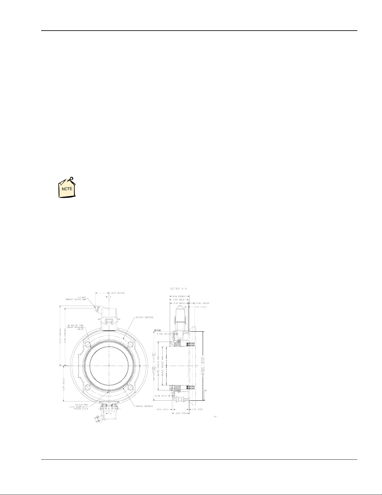
Figure 2: Specification Drawing.................................................................................................. 6
1.3 Specifications.............................................................................................................................................. 6
2 Installation......................................................................................................................................... 7
2.0 Inspection and Unpacking ................................................................................................................... 7
2.1 Painting Considerations....................................................................................................................... 7
2.2 Mechanical Installation........................................................................................................................ 7
Figure 3a: Large Thru-Shaft 1250............................................................................................... 7
Figure 3b: Large Thru-Shaft Assembly........................................................................................ 8
2.2.1 Motor Facing and Shaft ....................................................................................................................... 8
Figure 4: Typical 12.5 Inch Diameter Type C-Face Motor ......................................................... 9
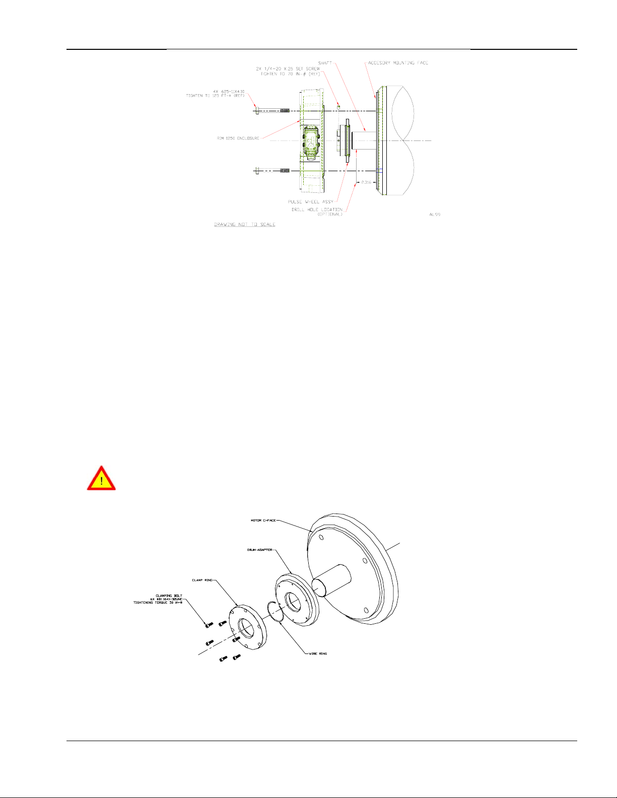
2.2.2 Pulse Wheel Assembly for Small and Large Thru-Shaft..................................................................... 9
Figure 5: Pulse Wheel Assembly.................................................................................................. 10
2.2.3 High Slew Rate Wheels....................................................................................................................... 10
Figure 6: High Slew Rate Wheel.................................................................................................. 10
2.2.4 Enclosure Installation .......................................................................................................................... 11
2.2.5 Pulse Wheel Assembly Axial Position Adjustment............................................................................. 12
Figure 7: Pulse Wheel Alignment Check Using Straight Edge .................................................... 12
2.2.5.1 Optional Pulse Wheel Alignment Check............................................................................................. 12
Figure 8: Optional Pulse Wheel Alignment Check w/ Depth Gauge............................................ 12
2.2.6 Sensor Module Installation.................................................................................................................. 13
Figure 9: Sensor Module Installation........................................................................................... 13
2.3 Electrical Installation........................................................................................................................... 13
2.3.1 Quick Release Connector Hood Wiring .............................................................................................. 14
Figure 10: Quick Release Connector Installation........................................................................ 14
Methods and apparatus disclosed and described herein have been developed solely on company funds of Dynapar No government or other contractual
support or relationship whatsoever has existed which in any way affects or mitigates proprietary rights of Dynapar in these developments. Methods and
apparatus disclosed herein may be subject to U.S. Patents existing or applied for. Dynapar reserves the right to add, improve, modify, or withdraw functions,
design modifications, or products at any time without notice. Dynapar shall not be liable for errors contained herein or for incidental or consequential
damages in connection with furnishing, performance, or use of this material.

NorthStar RIM Tach®1250 Instruction Manual
4 Dynapar (847) 662-2666 17 November 2008
CHAPTER 1
INTRODUCTION
1.0 Safety Summary
High current, voltage, and rotating parts can cause serious or fatal injury. The use of electric machinery, like all other uses of
concentrated power and rotating equipment, may be hazardous. Installing, operating, and maintaining electric machinery
should be performed by qualified personnel, in accordance with applicable provisions of the National Electrical Code and
sound local practices. Failure to comply with these precautions or with specific warnings elsewhere in this manual violates
safety standards of design, manufacture, and intended use of the instrument. Dynapar assumes no liability for the customer's
failure to comply with these requirements.
Rotating Machinery
Avoid contact with rotating parts. Avoid by-passing or rendering inoperative any safety guards or protection devices. Avoid
extended exposure in close proximity to machinery with high noise levels. Use proper care and procedures in handling,
lifting, installing, operating and maintaining the equipment.
Before Installation
Safe maintenance practices with qualified personnel is imperative. Before starting maintenance procedures, be positive that,
(1) equipment connected to the shaft will not cause mechanical rotation, (2) main machine windings have been disconnected
and secured from all electrical power sources, and (3) all accessory devices associates with the work area have been de-
energized. If high potential insulation test is required, follow procedures and precautions outlined in NEMA standards MG-1.
Grounding
Improperly grounding the frame of the machine can cause serious or fatal injury to personnel. Grounding of the machine
frame and structure should comply with the National Electrical Code and with sound local practices. Check wiring diagram
before connecting power.
Do Not Operate In An Explosive Atmosphere
Do not operate the instrument in the presence of flammable gases or fumes. Operating any electrical instrument in such an
environment constitutes a definite safety hazard.
Keep Away From Live Circuits
Operating personnel must not remove instrument covers. Component replacement and internal adjustments must be made by
qualified maintenance personnel. Do not replace components with power cable connected. To avoid injuries, always
disconnect power and discharge circuits before touching them.
Do Not Substitute Parts Or Modify Instrument
Do not install substitute parts or perform any unauthorized modification to the instrument. Introducing additional hazards is
dangerous. Return the instrument to an authorized Dynapar representative for service and repair to ensure that safety features
are maintained.
CAUTION!: Crucial information that must be read and followed regarding product functioning and
safety.
DO THIS!: Additional procedure that must be read and followed for proper operation, without safety
concerns.
NOTE: Useful information.
QUESTION: Helpful hints to answer your possible questions.

NorthStar RIM Tach®1250 Instruction Manual
5 Dynapar (847) 662-2666 17 November 2008
1.1 General
These instructions do not claim to cover all details of variation in equipment or to provide for every possible contingency or
hazard to be met in connection with installation, operation, and service. Should further information be desired or should
particular problems arise which are not covered sufficiently for the purchaser’s purposes, please contact Dynapar, or one of
its designated representatives.
1.2 Description
The RIM Tach®1250 is a high performance, reliable Digital Tachometer, designed to provide position and velocity feedback
from both AC and DC electric motors with pulse counts ranging from 60 through 2048 pulses per revolution. Designed for
NEMA 12.5 inch diameter type C-face motor frames, the RIM Tach 1250 utilizes rugged ductile iron casting construction,
and provides interchangeable sensor modules and a magneto-resistive technology capable of withstanding the harshest
industrial environments. This ensures a precise and consistent digital motor speed feedback.
The NorthStar RIM Tach®1250 is mounted directly to the motor frame and utilizes a patent pending, heavy-duty, one piece,
magneto-resistance sensor module with encapsulated surface mount electronics. The encapsulation provides resistance to
water, oil mist, dirt, high temperatures, and other harsh environments. The sensor module includes a 10-pin quick connector
requiring only a screwdriver for final electrical installation. The non-contact magneto-resistive sensor and rugged
magnetized pulse wheel are designed and machined to function properly without any adjustments when assembled to Type
C-Face (12.5-inch diameter) motor frame and accessory mount. There are no bearings to fail or requirements for flexible
couplings since the magnetized pulse wheel assembly is attached directly to the shaft.
Figure 2: RIM Tach1250 Specification Drawing

NorthStar RIM Tach®1250 Instruction Manual
6 Dynapar (847) 662-2666 17 November 2008
Figure 1: RIM Tach 1250 Small Thru-Shaft Enclosure
1.3 Specifications (subject to change without notice).
Electrical Specifications
Frequency Response 120 kHz
Pulse Code A, B, Z (Index), and compliments (A, B, Z)
Output Phases A phase, B phase @quadrature: 90phase, Z phase: Once per rev. (gated)
Pulse Duty Cycle 50 ±15% (within defined mechanical specifications)
Quadrature Accuracy 90 ±22% (within defined mechanical specifications)
Output Type High speed, differential driver
Rise and Fall Time Less than 1s @ 10,000 pf typical load
Current Consumption 45 mA typical plus line driver load
Output Current 150 mA maximum continuous
ESD Protection 2kV Mechanical Specifications
Maximum Operational Speed 7,000 RPM or 120 kHz
Nominal Air Gap 0.019 ±0.008”
Shaft Axial End Play Up to ±0.050”
Maximum Operational Speed 7,000 RPM (120khz)
Enclosure Configuration 12.5” motor face or accessory flange to meet NEMA MG1-4 standards
Acceleration Rate 3,600 RPM/sec (12,000 RPM/sec) with optional high slew rate pulse wheel
Enclosure Material Ductile iron casting
Sensor Module Stainless steel
Unit Dimensions / Weight 21” (534mm) x 15” (381mm) x 12” (305mm) / 35lbs. (16 kg.)
Box Dimensions / Weight 24” (610mm) x 15.5” (394mm) x 15.25” (388mm) / 2 lbs. (1 kg.)
Environmental Specifications
Operational Temperature -40to +80C
Operational Humidity Range Maximum of 90%
Chemical Resistance Salt spray, most solvents, mild acids and bases
Vibration Minimum 18 g’s RMS, 5-2000 Hz
Shock (Sensor Module) 1 meter drop tested, min. 30g’s
Interface Specifications
Power +5.0 to +15.0 VDC
Output Differential output swinging between Vcc - 0.6V and ground
Connector 10 pin industrial latching connector with ½” NPT fitting, IP-65 NEMA 4, 12 rated
Suggested Cable 22 - 16 AWG, 10 conductor , shielded, twisted pair

NorthStar RIM Tach®1250 Instruction Manual
7 Dynapar (847) 662-2666 17 November 2008
CHAPTER 2
INSTALLATION
2.0 Inspection and Unpacking
Inspect shipping container for external damage. All claims for damage (apparent or concealed) or partial loss of shipment
must be made in writing to Dynapar within (5) days from receipt of goods. If damage or loss is apparent, please notify the
shipping agent immediately.
Open shipping container and locate the packing list. The packing list is included to verify that all components, accessories,
and manual were received. Please use the packing list to check off each item as the unit is unpacked. Inspect for damage.
We recommend that the shipping container be retained for future shipping, storage, or return to factory purposes.
Dynapar cannot be responsible for any missing parts unless notified within 60 days of shipment.
2.1 Painting considerations
The enclosure may be painted. Please pay attention to the following considerations.
Corrosion preventative grease has been applied to the enclosure. Standard degreasing practices
must be followed before applying paint.
Do not hinder the latches on the connector if the connector is painted.
If the enclosure is painted before the sensor module(s) is added, be sure to mask off the area where the sensor module(s)
will be placed. The module must mate directly to the enclosure with nothing between. Failure to do this will degrade the
alignment of the system and may cause it to fail.
Ensure excess paint runoff does not clog Enclosure drain holes.
2.2 Mechanical Installation
The RIM Tach 1250 utilizes a modular
construction, allowing the user to configure
the unit as a one or two signal output
tachometers. Sensor modules are universal
and interchangeable. If one output requires
replacement, simply remove four screws,
and replace with a new sensor module. No
electrical adjustment or alignment is
required. Also, you never have to remove
the RIM Tach 1250 enclosure from the
motor. Other devices such as brakes or gear
reducers mounted from the RIM Tach 1250
do not need to be removed. After unpacking
the unit and verifying receipt of the items
listed on the packing list, you may proceed
with mechanical installation.
Figure 3a: Large Thru-Shaft 1250

NorthStar RIM Tach®1250 Instruction Manual
8 Dynapar (847) 662-2666 17 November 2008
Figure 3b: Large Thru Shaft Assembly
2.2.1 Motor Facing and Shaft
To prepare the motor facing and shaft for installation, perform the following steps. See Figure 4.
1. Clean outer rim and surface of motor facing and shaft of paint, grease, dirt, and other debris where RIM Tach 1250 unit
contracts motor or accessory. Also ensure that mating surfaces have not been damaged and that unit will fit squarely on
motor.
Ensure there is no paint, burrs, protrusions, or deformations on the motor facing or shaft. If the
enclosure does not fit squarely on the motor facing, the alignment between the sensor module
and the magnetic pulse wheel may be degraded.
2. Apply a thin layer of corrosion preventative or oil to motor facing and shaft to aid assembly.
The pulse wheel must be well attached during rapid acceleration or deceleration of the shaft.
The installer may elect to drill the set screw holes before installing the enclosure. Alternatively,
the installer may elect to install the enclosure, measure, then remove the enclosure before
drilling. Continue with Steps 3 through 5 if electing to predrill set screw holes. If not, proceed to
2.2.2 and continue with the installation procedure.
3. The pulse wheel assembly uses two set screws to hold the unit in place. These holes are at 90 degrees to each other and
located 2.316 ±0.005 inches from the motor facing.
4. Locate three holes using appropriate measuring equipment.
5. Use standard 17/64 inch bit to drill a hole that is 0.09 to 0.11 inches deep from the tangent point of the shaft
(point of first contact of the drill to the shaft) to the bottom of the hole. Do this for both holes.

NorthStar RIM Tach®1250 Instruction Manual
9 Dynapar (847) 662-2666 17 November 2008
Figure 4: Typical 12.5 Inch Diameter Type C-Face Motor
2.2.2 Pulse Wheel Assembly for Small and Large Thru-shaft
To prepare the pulse wheel assembly for installation, perform the following steps. See Figure 5.
Caution must be used when handling the pulse wheel assembly. The surface of the pulse wheel
outer rim is sensitive to scratches and impacts. The magnetic properties of the pulse wheel
material can also be distorted or erased by exposure to strong magnetic fields.
1. Remove pulse wheel assembly from packaging.
2. Leave protective red rubber band in place over pulse wheel.
3. Place assembly over the end of the shaft. The wheel side with the two set screws should be toward the outside, away
from motor.
Be sure the set screws in the adapter are retracted so that they will not interfere with the shaft
while mounting the unit.
4. Slide assembly on the shaft until there is about a 1 inch gap left between inner face of pulse wheel and motor facing. It
may be necessary to lightly tap the assembly to get it all the way on. The 1 inch gap is not a critical measurement.
Tap on the steel hub; not on the silver-colored aluminum magnetic wheel.
5. If you have already drilled set screw locating holes, align unit to holes and tighten set screws to a nominal 15 inch-
pounds. If you will not be using set screw locating holes or wish to use alternate method of adding them, just leave
assembly in place and continue to the Enclosure Installation.

NorthStar RIM Tach®1250 Instruction Manual
10 Dynapar (847) 662-2666 17 November 2008
Figure 5: Pulse Wheel Assembly
2.2.3 High Slew Rate Wheels
The following section discuses how to mount a high slew rate wheel (refer to Figure 6).
1. Loosen the screws around the outer portion of the wheel to approximately .030 inch gap. This will allow the inner
diameter ring enough space to move out of the way of the shaft. Do not to open the gap too far or the ring will move out
of the pocket it sits in.
2. Place the pulse wheel over the end of the shaft. The pulse wheel will stop at the ring. With a pen (or some other object
that will not damage the shaft ) work the ring around the shaft into the groove in the wheel. The wheel should then
completely slide on the shaft.
3. Place the housing on the motor using the four 0.625”-11 mounting hex cap screws. Bolt the housing to the motor. Align
the pulse wheel so that it is flush with the alignment surface of the housing.
4. Finally, tighten down the pulse wheel mounting bolts in a star pattern.
NorthStar recommends that if a brake is going to be used in conjunction with the encoder, the
encoder must use a high slew rate wheel. NorthStar considers <3600 RPM per second
acceleration or deceleration of the shaft to be a high slew rate wheel application.
Figure 6: High Slew Rate Wheel

NorthStar RIM Tach®1250 Instruction Manual
11 Dynapar (847) 662-2666 17 November 2008
2.2.4 Enclosure Installation
Do not attempt to mount or dismount the enclosure with sensor probe module(s) installed.
Remove all sensor modules until enclosure mounting is complete.
1. Remove red rubber band from pulse wheel. If test fitting the enclosure, leave rubber band in place until final enclosure
mounting.
2. Remove enclosure from packaging.
3. Determine which of two orientations of enclosure is best for this application (Sensor Modules horizontal or vertical).
If mounted horizontally, ensure that the drain hole is at bottom of enclosure. If not, rotate the unit
180°.
5. Place enclosure onto motor C-facing.
Do not damage the pulse wheel when mounting the enclosure. If the pulse wheel assembly is not
far enough down the shaft, continue pushing it on with the enclosure until the enclosure seats.
6. Tap lightly with hand or hammer if needed to make the enclosure slide over motor facing. Make sure clearance holes
remain aligned.
7. Insert four 0.625”-11 hex cap screws onto the motor enclosure. If the enclosure has not already seated against the
motor facing, do so by tightening the first bolt and then the bolt on the opposite side. Continue alternating and tightening
until enclosure is seated. Torque all bolts to a nominal 125ft-lbs (see Figure 5).
2.2.5 Pulse Wheel Assembly Axial Position Adjustment
If the pulse wheel is not lined up and no pre-drilled holes are required, use the following procedure to adjust the position of
the pulse wheel assembly. See Figure 4-6.
1. Slide pulse wheel assembly until the alignment surface of the unit is even with recess in face of enclosure. See Figure 2-
3 for a detailed drawing of the pulse wheel assembly.
2. Use a straight edge to check it.
3. Loosen two set screws and slide pulse wheel along the shaft until the recess and wheel surfaces are aligned to within
±0.010 inch.
4. Tighten two set screws to a nominal 70 in-lbs.
If the pulse wheel is not lined up and pre-drilled holes are desired, use the following optional procedure to locate (or
relocate) set screw holes in the shaft.
If pre-drilled screw holes turn out to be incorrectly placed, new screw holes must be drilled. New
holes may be drilled plus or minus the error distance from the old holes.
1. Leaving one set screw tightened, remove other set screw and use a punch to mark position of set screw hole on shaft.
2. Replace and tighten set screw. Remove other set screw and use a punch to mark position of that set screw hole on shaft.
3. Remove enclosure and pulse wheel.
4. Use standard ¼” drill to drill a hole that is approximately 0.1” deep from tangent point of shaft (point of first contact of
drill to shaft) to bottom of hole. Do this for both holes.
5. Reassemble pulse wheel and tighten set screws to a nominal 70 in-lbs.
6. Reassemble enclosure onto motor facing.

NorthStar RIM Tach®1250 Instruction Manual
12 Dynapar (847) 662-2666 17 November 2008
Pulse Wheel
Assembly
Enclosure
Drawing Not
To Scale
Recess
Side View
01
Straight
Edge
Front View
Shaft
Pulse Wheel
Assembly
Magnetic
Ring
Set
Screw
Set Screw Boss
Figure 7: Pulse Wheel Alignment Check Using Straight Edge
2.2.5.1 Pulse Wheel Alignment Check
An optional and more accurate pulse wheel alignment check procedure is provided as follows. See Figure 7.
1. Locate four 5/16-inch diameter access holes on recessed area in the face of the enclosure. Access holes are located on a
4.63 diameter Bolt Center (BC).
2. Using a calibrated depth measuring tool (depth gauge, vernier caliper, etc.), measure through access hole to obtain
distance between recessed surface on enclosure and aluminum magnetic ring underneath.
Ensure the gage is measuring the distance to the flat surface of the aluminum magnetic ring and
has not engaged the edge of the steel hub or slipped past the edge of the pulse wheel.
3. Repeat for all four access holes. Take an average of all four readings.
The range (difference between high and low measurements) of readings should be less than
0.005 inch. If the range of the readings is greater, than this, the pulse wheel is not perpendicular
to the shaft and will appear to wobble during shaft rotation. Tap the edge of the pulse wheel to
bring it back in line.
4. The distance between surface of the recess in the face of the enclosure and silver aluminum magnetic ring should be
0.792 ±0.010 inch. Otherwise, the position of the pulse wheel assembly should be adjusted. Refer to Paragraph 2.6 for
information on adjusting axial position of pulse wheel assembly.
F
r
o
n
t
Vi
e
w
Cover Plate
Threaded Hole
Drum/Hub
A
lignment Hole
Figure 8: Optional Pulse Wheel Alignment Check w/ Depth Gauge

NorthStar RIM Tach®1250 Instruction Manual
13 Dynapar (847) 662-2666 17 November 2008
2.2.6 Sensor Module Installation
1. Remove sensor module and mating connector from packaging.
Although the device is protected from Electrostatic Discharges up to 2000 Volts, standard ESD
precautions should be followed.
2. Separate mating connector from sensor module by releasing the two latches.
Use caution when handling the sensor module. The sensor at the end of the module can be
easily damaged by sharp objects. The sensor module can be damaged by sudden shocks
(dropping, hammer blows, etc.).
3. Insert sensor module into opening in enclosure. The sensor assembly is keyed to ensure proper orientation (blue side
goes toward motor facing).
4. Locate socket head screws. Insert the screws through clearance holes in sensor module and into tapped holes in
enclosure. Tighten to a nominal 7.5 in-lbs.
There should not be a gap between the lip on the housing and the enclosure. The stainless steel
sensor module is designed to seat in metal to metal contact with the enclosure. Ensure that no
gaskets, paint, dirt, etc., interferes with the complete seating of the module in the enclosure.
Figure 9: Sensor Module Installation
2.3 Electrical Installation
Electrical connections are made to the sensor module through a standard 1/2 inch NPT liquid tight flexible conduit. The
nipple length may be changed to extend the outlet box if desired. Interconnection cable recommendations are as follows:
stranded copper, 22 through 16 gage, braided or foil with drain wire shielding 0.05 F maximum total mutual or direct
capacitance, outer sheath insulated. Shrink tubing may be placed over any wires without insulation. For lengths over 100
feet, use 18 gage or larger, to a maximum of 1000 feet. If shielded twisted pair wire is used, do not cross channels. Keep
each pair of complementary channel outputs together in a single twisted pair (e.g., A and A ).

NorthStar RIM Tach®1250 Instruction Manual
14 Dynapar (847) 662-2666 17 November 2008
Reversing power and common will not damage the unit. However, applying power to any of the
sensor outputs may cause damage.
Signal Connector Pin Pigtail Cable MS 3102E18-IT#
Common
B
A
Z *
No Connection
Vcc (5-15 VDC)
/B
/A
/Z *
Shield
1
2
3
4
5
6
7
8
9
10
Black
Green
Blue
Violet
-----
Red
Yellow
Gray
Orange
Braid
A
E
D
C
-----
B
H
G
I
J
* Applies only to units with index pulse capability.
# Pinouts are for the sensors with the MS 3102E18IT connector
The shield in the sensor module is isolated from the frame of the encoder for maximum noise
immunity. Connect the shield wire or pin to the shield of the cable and that of the drive or other
receiving device.
2.3.1 Quick Release Connector Hood Installation
1. Remove the four screws from the mating connector housing that holds the terminal block in place. Remove terminal
block from housing.
2. Insert wiring through liquid tight flexible seal and mating connector housing. Leave enough wire exposed to
comfortably reach the terminal block. Wire to terminal block according to wire code in Table 1. A similar wiring list is
attached to enclosure.
There are two orientations of the connector hood. The terminal block can be inserted with either
the connector hood up or down. Choose the best direction for your application.
4. Tighten Liquid Tight fitting on housing. OPTIONAL: In some hostile environments, seal between connector body and
Sensor Module can be improved by smearing a sealant (silicone grease, etc.) on the neoprene seal of the connector.
5. Mate connector into place on sensor mount and snap the two latches into place. If only one sensor is being installed,
ensure cover plate is installed over other sensor hole.
Terminal Block
1/2 inch NPT
Mating Connector Housing
Liquid Tight Fitting
Conduit
Figure 10: Quick Release Connector Installation
Table of contents
Other DYNAPAR Measuring Instrument manuals
Popular Measuring Instrument manuals by other brands

Hanna Instruments
Hanna Instruments HI702 instruction manual

Honeywell
Honeywell DVC100 (M) MK2 installation guide

Endress+Hauser
Endress+Hauser Proline t-mass B 150 Brief operating instructions

Dynamica
Dynamica HALO DB-20 instruction manual

Kvarts
Kvarts DRSB-01 quick start guide

Clarke
Clarke CM265 User instructions

PCB Piezotronics
PCB Piezotronics 355M73 operating guide

SEP
SEP LEM012SD user manual

MICRODOS
MICRODOS MP2-HT PULSE Programming instructions

Valeport
Valeport fastCTD operating manual

Dwyer Instruments
Dwyer Instruments MFS2-3 Installation and operating instructions

Jäger Direkt
Jäger Direkt OPUS 55 SENS installation guide