Dynaset
Oy
|
Menotie
3,
33470
Ylöjärvi
|
puh.
03
3488
200
|
[email protected] |
www.dynaset.c
om
HYDRAULIC ROTARY VANE COMPRESSORS
TABLE OF PICTURES
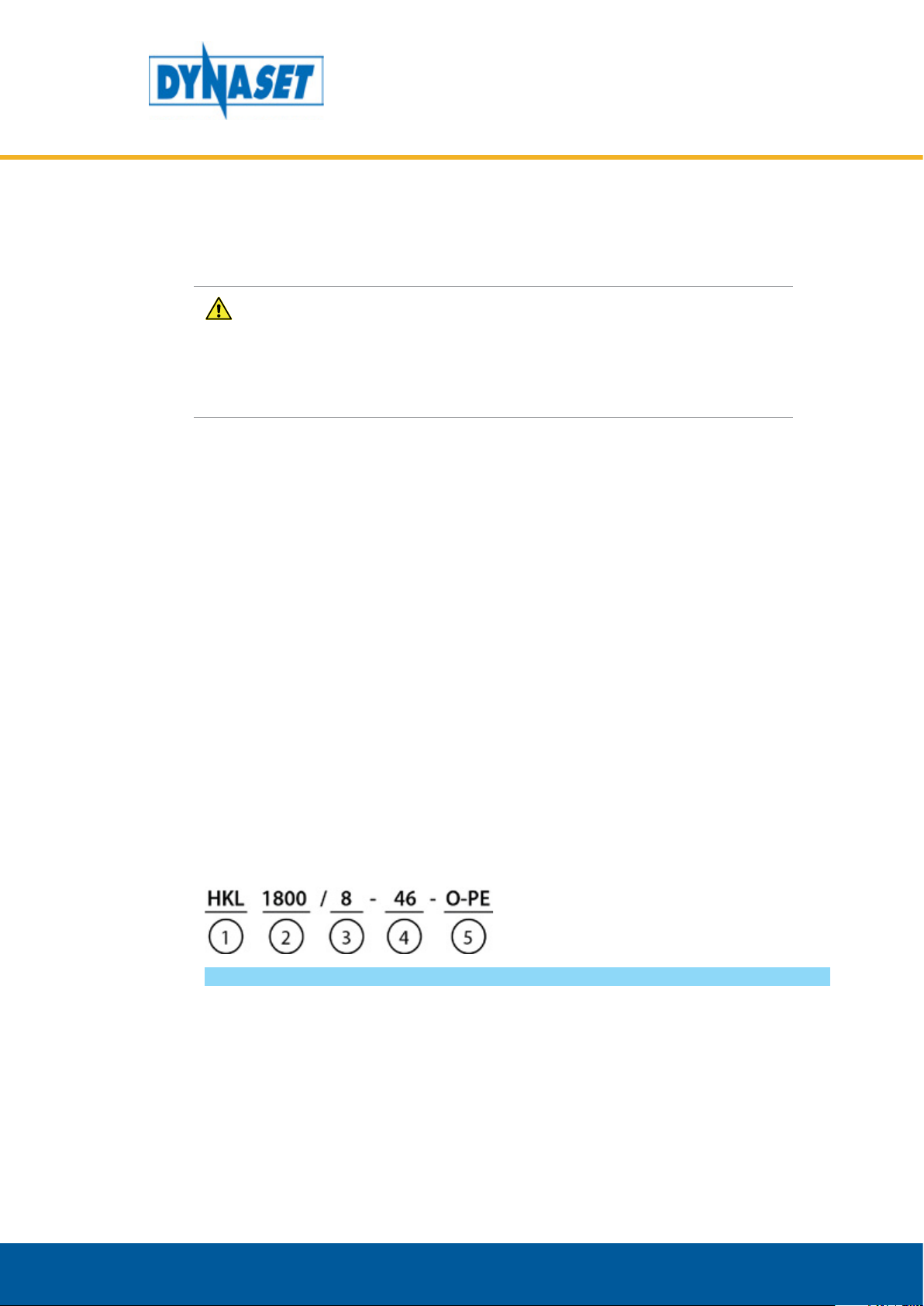
Picture 1: Identication key for HKL .................................................................................................................................7
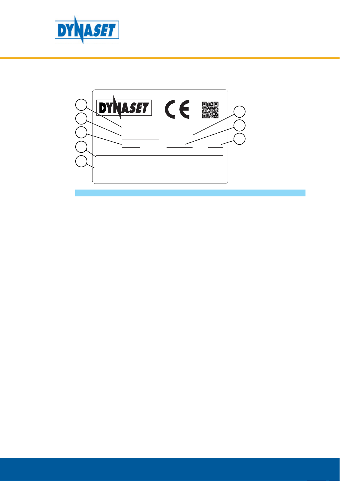
Picture 2: Type plate......................................................................................................................................................... 9
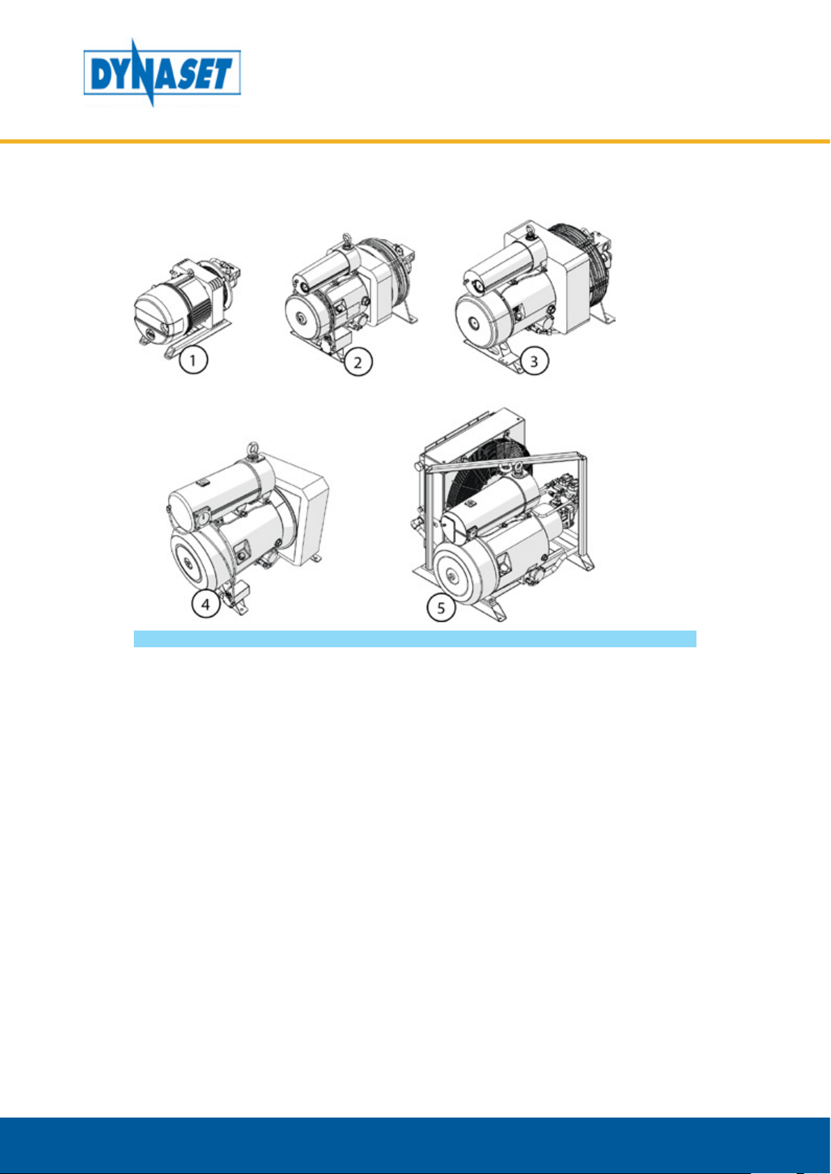
Picture 3: HKL compressor line-up .................................................................................................................................10
Picture 4: Main components of HKL compressor............................................................................................................. 11
Picture 5: Operating description: Air intake.................................................................................................................... 17
Picture 6: Operating description: Air compression and oil ltering................................................................................. 18
Picture 7: Operating description: Oil cooling .................................................................................................................. 19
Picture 8: The nominal discharge of HKL compressor......................................................................................................19
Picture 9: Automatic RPM-control.................................................................................................................................. 20
Picture 10: Pneumatic-electric o-load valve location...................................................................................................21
Picture 11: Temperature switch...................................................................................................................................... 22
Picture 12: Open centre hydraulic system with Load Sensing variable displacement pump ........................................... 26
Picture 13: Connection gure for open centre hydraulic system with Load Sensing variable displacement pump.......... 27
Picture 14: Closed centre hydraulic system with Load Sensing variable displacement pump .........................................28
Picture 15: Connection gure for closed centre hydraulic system with Load Sensing variable displacement pump........29
Picture 16: Hydraulic system with xed displacement pump .........................................................................................30
Picture 17: Connection gure for hydraulic system with xed discplacement pump......................................................31
Picture 18: Load Sensing valve LSV ................................................................................................................................32
Picture 19: Priority valve PV-SAE....................................................................................................................................32
Picture 20: Placing the compressor ................................................................................................................................33
Picture 21: Installing hydraulic hoses.............................................................................................................................33
Picture 22: P-line operational hydraulic ow..................................................................................................................34
Picture 23: Base machine pumps ................................................................................................................................... 34
Picture 24: Return line connection .................................................................................................................................34
Picture 25: Maximum inclination angle of HKL compressor............................................................................................ 35
Picture 26: Air supply system connection.......................................................................................................................36
Picture 27: Air supply line hose diameter and length..................................................................................................... 36
Picture 28: Oil level of the HKL compressor .................................................................................................................... 37
Picture 29: Starting the compressor...............................................................................................................................38
Picture 30: Normal operating ambient temperature ......................................................................................................39
Picture 31: Operating in extreme ambient temperatures............................................................................................... 40
Picture 32: Operation air humidity.................................................................................................................................40
Picture 33: Stopping the compressor.............................................................................................................................. 41
Picture 34: Depressurization of the HKL compressor.......................................................................................................43
Picture 35: Cleaning oli cooler........................................................................................................................................46
Picture 36: Location of oil ller cap ................................................................................................................................ 46
Picture 37: Oil level of the HKL compressor .................................................................................................................... 47