EKOM DK50 2x4VR/110/M User manual

DK50 2x4VR/110
User manual
Benutzerhandbuch
Návod na použitie


COMPRESSOR
KOMPRESSOR
KOMPRESOR
DK50 2x4VR/110/M
EKOM spol. s r. o.
Priemyselná 5031/18
SK-921 01 Piešťany
Slovak Republic
tel.: +421 33 7967255
fax: +421 33 7967223
www.ekom.sk
email: eko[email protected]k
DATE OF LAST REVISION
DATUM DER LETZTEN ÜBERARBEITUNG
DÁTUM POSLEDNEJ REVÍZIE
09/2020
NP-DK50 2x4VR 110-AD-A-
1_09-2020
112000518-000

CONTENTS.................................................................................................. 4
INHALT........................................................................................................ 57
OBSAH ........................................................................................................111

CONTENTS
09/2020 5 NP-DK50 2x4VR 110-AD-A-1_09-2020
CONTENTS
GENERAL INFORMATION............................................................................................................6
1. CONFORMITY WITH THE REQUIREMENTS OF THE EUROPEAN UNION...................6
2. SYMBOLS........................................................................................................................6
3. DEVICE USE ...................................................................................................................7
4. GENERAL SAFETY INSTRUCTIONS..............................................................................8
5. STORAGE AND TRANSPORT CINDITIONS...................................................................9
PRODUCT DESCRIPTION ..........................................................................................................10
6. VARIANTS.....................................................................................................................10
7. ACCESSORIES.............................................................................................................11
8. PRODUCT FUNCTION..................................................................................................11
TECHNICAL DATA......................................................................................................................16
INSTALLATION...........................................................................................................................19
9. INSTALLATION CONDITIONS ......................................................................................19
10. COMPRESSOR ASSEMBLY.........................................................................................19
11. PNEUMATIC CONNECTION.........................................................................................22
12. ELECTRICAL CONNECTION........................................................................................26
13. COMMISSIONING .........................................................................................................30
14. PNEUMATIC AND ELECTRICAL DIAGRAMS...............................................................31
OPERATION................................................................................................................................34
15. SWITCHING ON THE COMPRESSOR..........................................................................35
16. SWITCHING OFF THE COMPRESSOR........................................................................35
17. AD DRYER OPERATING MODES:................................................................................35
PRODUCT MAINTENANCE ........................................................................................................38
18. PRODUCT MAINTENANCE...........................................................................................38
19. LONG-TERM SHUTDOWN............................................................................................53
20. DISPOSAL OF DEVICE.................................................................................................53
TROUBLESHOOTING.................................................................................................................54
21. REPAIR SERVICE.........................................................................................................56
ANNEX ......................................................................................................................................163
22. INSTALLATION RECORD ...........................................................................................163

GENERAL INFORMATION
NP-DK50 2x4VR 110-AD-A-1_09-2020 6 09/2020
GENERAL INFORMATION
Carefully read this user manual before using the product and carefully store it for future reference.
The user manual aids in the proper use, including installation, operation and maintenance, of the
product.
The user manual corresponds to the configuration of the product and its compliance with applicable
safety and technical standards at the time of its printing. The manufacturer reserves all rights for the
protection of its configuration, processes and names.
The Slovak version represents the original version of the user manual. The translation of the user
manual is performed in accordance with the best available knowledge. The Slovak version is to be
used in the event of any uncertainties.
The user manual is original and the translation is performed with the best available knowledge.
1. CONFORMITY WITH THE REQUIREMENTS OF THE EUROPEAN UNION
This product conforms to the requirements of the European Union 2006/42/EC, 2014/29/EU,
2014/35/EU, 2014/30/EU, 2011/65/EU and is safe if used in compliance with the intended use and
if all safety instructions are followed.
User manual is in compliance with requirements of Directive 2006/42/EC.
2. SYMBOLS
The following symbols and marks are used in the User manual, on the device and its packaging:
General warning
Warning - risk of electric shock
Warning - compressor is controlled automatically
Warning - hot surface
General caution
Read the operating instructions
Refer to instruction manual
CE –marking
Serial number
Protecting earthing
Fuse

GENERAL INFORMATION
09/2020 7 NP-DK50 2x4VR 110-AD-A-1_09-2020
Compressed air inlet
Compressed air outlet
Control wire input
Package handling label –fragile
Package handling label –this side up
Package handling label –keep dry
Package handling label –temperature limits
Package handling label –limited stacking
Package label –recyclable material
Manufacturer
3. DEVICE USE
3.1. Intended use
The compressor is used as source of clean oil-free compressed air intended to be used in industry
and laboratories, where parameters and properties of the compressed air are suitable.
The compressor is exclusively intended to compress air without content of explosive or chemically
unstable substances.
The compressor is intended for operation in clean and dry rooms.
3.2. Incorrect use
Contamination risk.
Air from the compressor iswithout additionaltreatment not suitable forbreathing
and direct contact with food
Explosion risk.
The product is not intended for operation in rooms with explosion risk.
The compressor must not be used to compress aggressive gases.
The compressor must not be operated in premises with occurrence of flammable vapors.
The compressor must not be operated in other conditions as mentioned in Technical data.
Any other use of the product beyond the intended use is considered as incorrect use. The
manufacturer is not responsible for any damages or injuries as a result of incorrect use or
disobedience to instructions stated in this User manual. All risks shall be solely borne by the
user/operator.

GENERAL INFORMATION
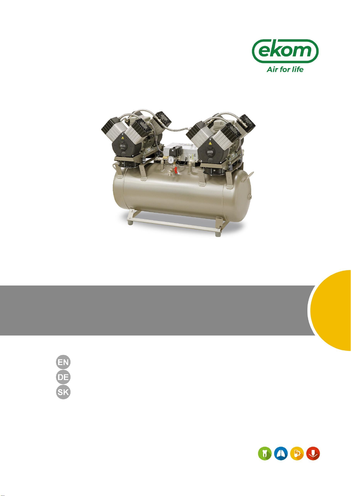
NP-DK50 2x4VR 110-AD-A-1_09-2020 8 09/2020
4. GENERAL SAFETY INSTRUCTIONS
The product is designed and manufactured so that any risks connected with its use are minimized
and the product is safe for the user and surrounding when used according to the intended use and
the instructions stated below are followed.
4.1. Required qualification of the personnel
Each user must be trained by the manufacturer or an organization authorized by the
manufacturer or instructed on the device operation by other trained user.
Installation, new settings, changes, extensions and repairs of the product may be performed by
the manufacturer or an organization authorized by the manufacturer (hereinafter qualified
technician).
- Otherwise the manufacturer is not responsible for safety, reliability and correct functioning
of the product.
4.2. General instructions
When operating the compressor, all acts and local regulations valid in the place of use must be
observed. The operator and user are responsible for following the applicable regulations.
Before every use, the user must check, if the device is functioning correctly and safely. Before
building the compressor in other devices, the supplier must assess, if the supplied air and
construction of the device comply with the requirements of the specified intended use. Taking
this into account, follow the product technical data. Assessment of conformity shall be performed
by the manufacturer –supplier of the final product.
4.3. Protection from dangerous voltage and pressure
The equipment may only be connected to a properly installed socket connected to earth
(grounded).
Before the product is plugged in, make sure that the mains voltage and frequency stated on the
product are the same as the power mains.
Check for any damage to the connected compressed air system and electrical circuits before
use. Replace damaged pneumatic and electrical conductors immediately.
Immediately disconnect the product from the mains (remove the power cord from the socket) in
hazardous situations or when a technical malfunction occurs.
Never adjust or use the safety valve to release the air pressure in the air tank.
Never adjust or use pressure relief valves to release air pressure from the device.
4.4. Original spare parts and accessories
Only the use of original parts guaranteesthe safety of operating personnel and flawless operation
of the product itself. Only accessories and replacement parts specified in the technical
documentation or expressly approved by the manufacturer may be used.
The warranty does not cover damage resulting from the use of other accessories and
replacement parts as specified or recommended by the manufacturer and the manufacturer has
no related liability.

GENERAL INFORMATION
09/2020 9 NP-DK50 2x4VR 110-AD-A-1_09-2020
5. STORAGE AND TRANSPORT CINDITIONS
The compressor is shipped from the manufacturer in transport packaging. This protects the product
from damage during transport.
Potential for damage to pneumatic components.
The compressor must be transported only when all air has been vented. Before
moving or transporting the compressor, release all the air pressure from the tank
and pressure hoses, from dryer chambers and drain condensate from the tank
and from the condensate separator on the dryer.
Keep the original factory packaging in case the device needs to be returned Use
the original factorypackaging during transport asit provides optimum protection
for the product. . If it is necessary to return the product during the warranty
period, the manufacturer is not liable for damages caused by improper
packaging.
The compressor is shipped in a vertical position and must be secured using
transport straps.
Protect the compressor from humid and dirty environments and extreme temperatures
during transport and storage. Do not store near any volatile chemical substances.
If not, please dispose of the original packaging material in an environmentally-friendly
way. The packaging cardboard can be recycled with old paper.
5.1. Ambient conditions
Products may only be stored and transported in vehicles that are free of any traces of volatile
chemicals under the following climactic conditions:
Temperature
–25°C to +55°C, 24 h at up to +70°C
Relative humidity
max. 90% (non-condensing)
Storing or shipping the equipment in any conditions other than those specified below is
prohibited.

PRODUCT DESCRIPTION
NP-DK50 2x4VR 110-AD-A-1_09-2020 10 09/2020
PRODUCT DESCRIPTION
6. VARIANTS
The compressor is manufactured according to its intended application in the following variants:
DK50 2x4VR/110/M
Compressor with adsorption dryer
DK50 2x4VR/110S/M
Compressor in cabinet with adsorption dryer
Cabinet S110R
It decreases noise level of the compressor.
DK50 2x4VR/110/M
S110R
DK50 2x4VR/110S/M

PRODUCT DESCRIPTION
09/2020 11 NP-DK50 2x4VR 110-AD-A-1_09-2020
7. ACCESSORIES
Accessories that are not included in the standard order must be ordered separately.
Set of compressed air outlet filters
The compressor may be equipped with a set of filters if specified. The filter set may be equipped
with an air pressure regulator.
Where a different level of air filtration is required, this requirement must be
agreed upon with the supplier and specified in the order.
Type
Use
Level of filtration
(µm)
Bypass
function *
Article number
FS 40F
DK50
2x4VR/110
1
no
604014119-000
FS 40M
1+0.1
604014119-004
FS 40S
1+0.01
604014119-024
FS 40AH
1+AC+HC (0.01)
604014119-005
*) These FS do not contain a filter bypass, which will ensure a continuous flow of air when replacing
the filter element. Such a set must be ordered separately.
Filter set regulator assembly
The compressor may beequipped with a pressure regulator of the compressed air outlet if specified.
The regulator must be selected according to the application to the filter set, or separately The
regulator shall ensure constant pressure at the outlet.
Type
Use
Article number
Regulator complete
DK50 2x4VR/110/M
604014125-000
REG15
447000001-243
Filter set brackets
A suitable bracket must be ordered for every filter set.
8. PRODUCT FUNCTION
8.1. Compressor with adsorption dryer
The compressor aggregate (1) draws in air through the inlet filter (8) and compresses it through a
check valve (3) and into a manifold, from which it is routed to the adsorption dryer (9) through a
connecting hose. From the inlet to the dryer module, the air is first cooled in the integrated cooler
(14) and then moves through the condensate separator (40), entering the active chamber with
adsorbent (16), where the air is dried. A portion of the air is fed into the second, regeneration
chamber, where this air is used to remove moisture from the adsorbent, after which it is released
through the silencer (38). The active chamber switches on a cyclical basis. The dry and filtered air
then passes through the check valve (3) into the air tank (2).
Type
Use
Article number
Compressor-mounted bracket
DK50 2x4VR/110/M
604014131-000
Wall-mounted bracket
603014120-000

PRODUCT DESCRIPTION
NP-DK50 2x4VR 110-AD-A-1_09-2020 12 09/2020
8.2. Compressor cabinet
The soundproof cabinet provides compact covering of the compressor, dampens noise efficiently,
providing sufficient exchange of cooling air. The fan (10) under the compressor pump provides
cooling of the compressor. It is in operation at the same time with the compressor motor or after
switching on the temperature switch at temperature above 40°C. After cooling the cabinet area
approximately under 32°C, the fan turns off automatically.
Risk of compressor overheating.
Make sure that there are no obstacles at the cooling air inlet into the cabinet
(around the bottom part of the cabinet) and at the hot air outlet on the top back
side of the cabinet.
If the compressor is placed on a soft floor, e.g. carpet, create space between the
base and the floor or the cabinet and the floor, e.g. underlay the footings with
hard pads to ensure sufficient cooling of the compressor.
Descriptions for figures 1 - 3
1 Air pump
2 Air tank
3 Non-return valve
4 Pressure switch
5 Safety valve
6 Pressure gauge
7 Drain valve
8 Inlet filter
9 Adsorption dryer
10 Compressor fan
11 Magnetic holder
12 Condensate collection vessel
13 Compressed air outlet
14 Cooling module
15 Inlet valve module
16 Dryer chamber
17 Outlet module
18 Control unit
19 Cabinet gas springs
20 Wall stop
21 Power supply cord
22 Pressure gauge hose
23 Elbow fitting
24 –
25 Compressor wheel
26 Cabinet fan
27 Handle
28 Switch
29 Maintenance indicator
30 Cabinet pressure gauge
31 -
32 -
33 Regeneration solenoid valve
34 Regeneration solenoid valve
35 Inlet solenoid valve
36 Inlet solenoid valve
37 Relief valve
38 Noise silencer
39 Compressed air inlet
40 Condensate separator
41 Pressure gauge
42 Automatic condensate drain
43 Dryer pan
44 Air outlet

PRODUCT DESCRIPTION
09/2020 13 NP-DK50 2x4VR 110-AD-A-1_09-2020
Fig. 1: DK50 2x4VR/110/M –Compressor with adsorption dryer

PRODUCT DESCRIPTION
NP-DK50 2x4VR 110-AD-A-1_09-2020 14 09/2020
Fig. 2: Adsorption dryer

PRODUCT DESCRIPTION
09/2020 15 NP-DK50 2x4VR 110-AD-A-1_09-2020
Fig. 3: Cabinet

TECHNICAL DATA
NP-DK50 2x4VR 110-AD-A-1_09-2020 16 09/2020
TECHNICAL DATA
Compressors are designed for operation in dry, ventilated and dust-free indoor rooms under the
following climactic conditions:
Temperature
+5°C to +40°C
Relative humidity
max. 70%
Working pressure 6 –8 bar
DK50 2x4VR/110/M
DK50 2x4VR/110S/M
Nominal voltage
Frequency a)
V, Hz
3x400V, 50Hz
3x400V, 50Hz
Capacity at 6 bar
(FAD) -20°C
l/min
450
450
Working pressure b)
bar
6.0 –8.0
6.0 –8.0
Max. current
A
9.0
9.8
Motor power
kW
2x2.2
2x2.2
Air tank volume
l
110
110
Air quality - filtration
m
-
-
Maximum operating
pressure of safety
valve
bar
9.0
9.0
Noise level at 5 bar
(LpA)
dB
≤76.7
≤58.0
Operating mode
%
S1-100
S1-100
PDP drying
performance at 7 bar d)
°C
-20
-20
Time to fill air tank
from 0 to 7 bar
s
88
88
Dimensions (net)
w x d x h
mm
2000x503x965
2000x834x1045
Net weight c)
kg
186 c)
286 c)
a) Specify the compressor version when ordering
b) Consult any other range of pressure with the supplier
c) Weight is indicative and only applies to the product without accessories
d) Applies to ambient temperatures of <30°C PDP – pressure dew point
Dependence of compressor output on working pressure

TECHNICAL DATA
09/2020 17 NP-DK50 2x4VR 110-AD-A-1_09-2020
Working pressure 8 –10 bar
DK50 2x4VR/110/M
DK50 2x4VR/110S/M
Nominal voltage
Frequency a)
V, Hz
3x400, 50
3x400 , 50
Capacity at 8 bar
(FAD) -20°C
l/min
345
345
Working pressure b)
bar
8.0 –10.0
8.0 –10.0
Max. current
A
9.4
10.2
Motor power
kW
2x2.2
2x2.2
Air tank capacity
l
110
110
Air quality - filtration
m
-
-
Maximum operating
pressure of safety
valve
bar
12.0
12.0
Noise at 5 bar (LpA)
dB
≤76.7
≤58.0
Operating mode
%
S1-100
S1-100
PDP drying
performance at 7 bar d)
°C
-20
-20
Time to fill air tank
from 0 to 7 bar
s
121
121
Dimensions (net)
w x d x h
mm
2000x503x965
2000x834x1045
Net weight c)
kg
186 c)
268 c)
a) Specify the compressor version when ordering
b) Consult any other range of pressure with the supplier
c) Weight is indicative and only applies to the product without accessories
d) Applies to ambient temperatures of <30°C PDP –pressure dew point
Dependence of compressor output on working pressure

TECHNICAL DATA
NP-DK50 2x4VR 110-AD-A-1_09-2020 18 09/2020
FAD correction of capacity for altitude
Capacity given in the form of FAD („Free Air Delivery“) applies to the following conditions:
Altitude
0 m.n.m.
Temperature
20°C
Atmospheric pressure
101325 Pa
Relative humidity
0%
To calculate FAD compressor capacity in dependence on altitude, it is necessary to apply correction
factor according to the following table:
Altitude [m.n.m.]
0 -1500
1501 - 2500
2501 - 3500
3501 - 4500
FAD correction factor
1
0.80
0.71
0.60

INSTALLATION
09/2020 19 NP-DK50 2x4VR 110-AD-A-1_09-2020
INSTALLATION
Risk of incorrect installation.
Only a qualified technician may install the compressor and place it into operation
for the first time. Their duty is to train operating personnel on the use and
maintenance of the equipment. An entry is made in the equipment installation
record to certify installation and operator training. (see the Annex chapter)
9. INSTALLATION CONDITIONS
The compressor may only be installed and operating in dry, well-ventilated and clean
environments under the conditions specified in the Technical Data chapter.
Risk of damage to the device.
The equipment may not be operated outdoors or in otherwise wet or damp
environments.
Risk of explosion.
Do not use the equipment in the presence of explosive gases, dust or
combustible liquids.
Burn or fire hazard! Caution! Hot surface!
Portions of the compressor, dryer and connecting hoses between the dryer and
compressor may be hot and reach hazardous temperatures during compressor
operation that may harm materials or operating staff.
The compressor must be installed so that it is accessible at all times for operating and
maintenance. Please ensure that the nameplate on the device is readily accessible.
The compressor must stand on a flat, sufficiently stable base (be aware of the weight of the
compressor, see the Technical Data chapter).
High temperature hazard.
The placement of air flow impediments upstream or downstream of the cooler is
prohibited. The temperature of internal and external parts of the cooler may be
hot and reach hazardous temperatures.
10. COMPRESSOR ASSEMBLY
10.1. Handling and releasing the compressor
Unpack the compressor from the packaging.
Position the compressor at the site of installation. (Fig. 4)
Use the handles on the compressor to move the compressor as needed. Do not
use other parts of the compressor (the aggregate, cooler, etc.) for grip

INSTALLATION
NP-DK50 2x4VR 110-AD-A-1_09-2020 20 09/2020
Fig. 4: Handling the compressor
Remove the transport stabilisers from the air pumps (Fig. 5).
Prior to installation, ensure that the compressor is free of all transport packaging
and stabilizers to avoid any risk of damage to the product.
Remove all devices used to secure the aggregates once the compressor is
installed and levelled at the site of final installation.
Fig. 5: Releasing the air pumps
Assembly of the AD dryer
Remove the dryer from the packaging.
Install the dryer in its operating position (Fig. 6).
At least two persons are needed to handle the equipment.
Integrated handles are installed on the lower brackets on the product. Each person must grasp the
equipment with one hand on a handle and the other behind the dryer chamber when moving the
equipment.
Table of contents
Languages:
Other EKOM Compressor manuals

EKOM
EKOM DK50 4x2VT/M User manual

EKOM
EKOM DK50 2V S User manual

EKOM
EKOM DK50 4x4VRT/M User manual

EKOM
EKOM DK50 4x2VT/M User manual

EKOM
EKOM DK50 2V/110 Owner's manual

EKOM
EKOM DK-50 2x2V/110 User manual

EKOM
EKOM DK50 4x4VRT/M User manual

EKOM
EKOM DK50 D User manual

EKOM
EKOM DK50 2V/50 User manual

EKOM
EKOM DK50 2V S User manual
Popular Compressor manuals by other brands

Branick
Branick 7600 Installation, Operation & Repair Parts Information

SCANGRIP
SCANGRIP CANVIK CENTER operating instructions

mxr
mxr Dyna Comp Deluxe User manual/operation instructions

Sealey
Sealey RE2280 instructions

Panasonic
Panasonic Matsushita S51C90JAU6 Specification sheet

KAESER
KAESER BSD 40 Service manual