PRESTI
ANI
Copyright:
Dynatech
Nevada,
Inc.
agrees
to
a
limited
copyright
release
that
allows
you
to
reproduce
manuals
and
other
printed
materials
for
use
in
service
training
programs
and
other
technical
publications.
If
you
would
like
other
reproductions
or
distributions,
submit
a
written
request
to
Dynatech
Nevada
Inc.
Warranty
and
Product
Support:
This
instrument
was
thoroughly
tested
and
found
to
meet
our
manufacturing
specifications
when
it
was
shipped
from
the
factory.
Calibration
measurements
are
traceable
to
the
National
Institute
of
Standards
and
Technology
(NIST).
New
Instrument
Warranty
1
year
on
parts
and
labor
Physical
damage
is
not
covered
Repair
Instrument
Warranty
90
days
on
calibration,
labor,
and
parts
replacement
Y
Physical
damage
is
not
covered
i
Dynatech
Nevada
Inc.
warrants
that
all
products
are
to
be
free
from
defects
in
parts
and
labor
as
described
in
the
warranty
policy
unless
a
different
period
is
specified.
If
you
discov-
era
defect,
Dynatech
Nevada
will
either
modify
the
product
to
correct
the
defect,
replace
the
product
with
new
or
factory
reconditioned
products,
or
refund
the
amount
paid
for
the
defective
product.
The
standard
terms
and
conditions
of
sale
are
printed
on
the
reverse
side
of
the
Dynatech
Nevada
invoice.
You
may
obtain
additional
copies
of
the
warranty
and
conditions
of
sale
from
Dynatech
Nevada.
If
you
retum
an
instrument
to
Dynatech
Nevada
Inc.,
we
recommend
United
Parcel Service,
Federal
Express,
or
Air
Parcel
Post.
You
must
receive
prior
authorization
from
Dynatech
Nevada
Inc.
for
C.O.D.
shipments,
otherwise
you
will
pay
transportation
charges.
Intended
Use
Disclaimer:
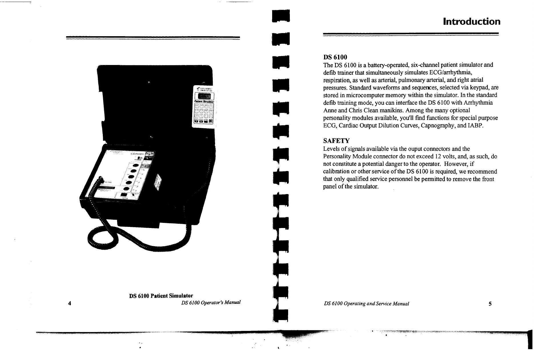
The
DS6100
is
intended
to
be
used
as
a
simulation
device
only.
Recommended
applications
include
routine
preventive
maintenance
inspections,
sales
demonstrations,
or
training.
The
DS6100
is
not
to
be
used
as
the
primary
calibration
stan-
dard
or
the
certification
test
instrument
for
medical
devices.
Dynatech
Nevada
Inc.
2000
Arrowhead
Drive,
Carson
City,
NV
89706-0403
P.O.
Box
1925,
Carson
City,
Nevada
89702-1925
800-648-7952
702-883-3400
Fax:
702-883-9541
Part
Number:
9508-0213
Revision:
C
Printed
in
the
USA.
Table
of
Contents
INTRODUCTION
..
5
FRONT
PANEL
........
6
OPERATION
.
10
USING
THE
PENDANT
KEYPAD
hrs
10
KEYPADCONTROLS
.…………
20000
11
MODIFTER/CAL
MODE
...........ccccccocsscsscscsccscevssessccsecsesece
LT
SIZE
ADJUSTMENTS:
SPEC
FUNC
54
ue.
18
CALIBRATION
LEVELS:
SPECFUNC78,82,&$4.....................
20
HEART
RATE
ADJUSTMENT:
SPEC
FUNC
53
.....................
21
ARTIFACT
SIMULATION:
SPEC
FUNC
47,
48,
8:
49
............
21
RESPIRATION
.
ee
22
DEFIB
SEQUENCE
..
..
seveso
...
24
PERSONALITY
MODULES
sense
ee
26
INTERACTIVE
IABP
PERSONALITY
MODULES
..............06
28
CARDIAC
OUTPUT
PERSONALITY
MODULES
...................
30
CAPNOGRAPHY
PERSONALITY
MODULE
.........................
32
BP
CABLES
...
...
a
„33
WIRING
CHARTS
…
34
CONNECTOR
INTERFACE
..........ccscssscsssssssscssesseorseessrsses
25
BATTERY
CARE
ee
6
PARTS
LIST/SCHEMATICS
ses
37
Table
of
Figures
Fig
1:
12
Lead
ECG
Amplitudes...6
Fig
8:
Artifact
Modifier.....................
21
Fig
2:
Front
Control
Panel........
8
Fig
9:
Wiring
5uV/VmmHg
monitor
..
34
Fig
3:
Pendant
Keypad.................
9
Fig
10:
Wiring
40uV/WVmmHg
monitor
.
34
Fig
4:
Modifier/Cal
Mode
............
17
Figll:
ECGConnecor..............
35
Fig5:Sizeddjwsi..................
19
Fig
12:
Pressure
Connectors
............
35
Fig
6:
Calibration
Functions
........
20
Fig
13:
Connector
Pin
Assignments
..
35
Fig
7:
Heart
Rate
Adjustment
.......
21