Dynisco Vertex User manual

P/N: 974155 | Rev: 091316 | ECO: 46774
www.dynisco.com
From lab to production,
providing a window into the process
-1-
HgfreeIntrinsicallysafepressuresensors
designedspecificallyforextrusionand
polymerprocessingapplications
OperatingManual
DyniscoVertex™MeltHgFree
PressureSensors

P/N: 974155 | Rev: 091316 | ECO: 46774
www.dynisco.com
From lab to production,
providing a window into the process
-2-
DYNISCOVERTEXQUICKSTARTCARD
ThisQuickStartSetupguidecanbeusedbyexperiencedinstrumentationtechnicianstoconfigurethe
sensorusingtheZeroandSpanactuatorsorviatheoptionalHARTcommunications.Formore
detailedinformation,pleaseconsultthecompletemanualbeforeoperating.TheQuickStart
procedureisintendedforusersalreadyfamiliarwiththeuseofMeltPressureSensorsand
Instrumentation.
1. Insuretheprocessconnectioniscleanandclearofanydebrisandismachinedtothe
properdimensions.Machinetoolkitswithportgagesareavailable(seesections6&
12ofmanual)
2. Applyanti‐seizeasappropriatetheninstallthesensorintotheprocessconnection.
(DoNOTtorquesensorintotheholeatthistime!)
3. Allowtimeforthesensortemperaturetoequalizetotheprocesstemperature.Thiswill
helpeliminatethreadgallingandeaseremovallater.ThereshouldbeNOpressure
appliedatthistime.
4. Connectpowertothesensorusingthechartbelow.Standardconfigurationsshown.
Seecompletemanualformoreoptions:
mV/VVoltage mA
6‐Pin8‐PinConduit6‐Pin6‐Pin8‐PinConduit
Excitation
Voltage10‐12VDC16‐36VDCExcitation
Voltage
16‐36VDC
SIG(+)ABREDAPWR/SIG
(+)AARED
SIG(‐)BDBLKBPWR/SIG
(‐)BBBLK
PWR(+)CAWHTCRCAL(+)FEORG
PWR(‐)DCGRNDRCAL(‐)EDBLU
RCAL(+)FFORGF
RCAL(‐)EEBLUE
5. Aftertemperatureshaveequalized,applytorque(250in‐lbstypical)andtighten
transmitterintomountinghole.
6. PerformZeroFunction
mV/Vunitscanonlybezeroedwhenfeatureisavailableonyour
indicator/controller.Nolocalzerocapability.
Voltageunitscanbezeroedusingonboardzeropotentiometer.Remove

P/N: 974155 | Rev: 091316 | ECO: 46774
www.dynisco.com
From lab to production,
providing a window into the process
-3-
sealscrewandadjustpotentiometeruntildesiredoutputisachieved.
Replacesealscrewwhencomplete.
mAunitshaveavarietyofonboardZeroAdjustmentstypes(based
onconfiguration),i.e.potentiometer,pushbuttons,andHALLEffect
Switches.
oForunitswithpotentiometers,removesealscrewandadjust
potentiometeruntildesiredoutputisachieved.Replacesealscrew
whencomplete.
oForunitswithpushbuttons,removesealscrew,usinga2mmorsmaller
AllenKey,depresspushbuttonfor½sec,releasepushbuttonfor½sec,
depresspushbuttonfor½secandrelease.Replacesealscrewwhen
complete.
oForunitswithHALLEffectSwitches,unthreadzeroscrewfromendplate,
depressscrew,releasescrew,depressscrew,releasescrewandreturn
screwinendplate(failuretoreturnthescrewonunitswithHALLEffects
Switcheswillcausetheunittogointofailsafe).
DYNISCOVERTEXQUICKSTARTSETUPGUIDEUTILIZINGHARTCOMMUNICATOR
ThissectiononlyappliestomAHARTunits.
1. Followsteps1through5fromDYNISCOVERTEXQUICKSTARTSETUPGUIDE.
2. ConnectHARTHandheldtotheloop.
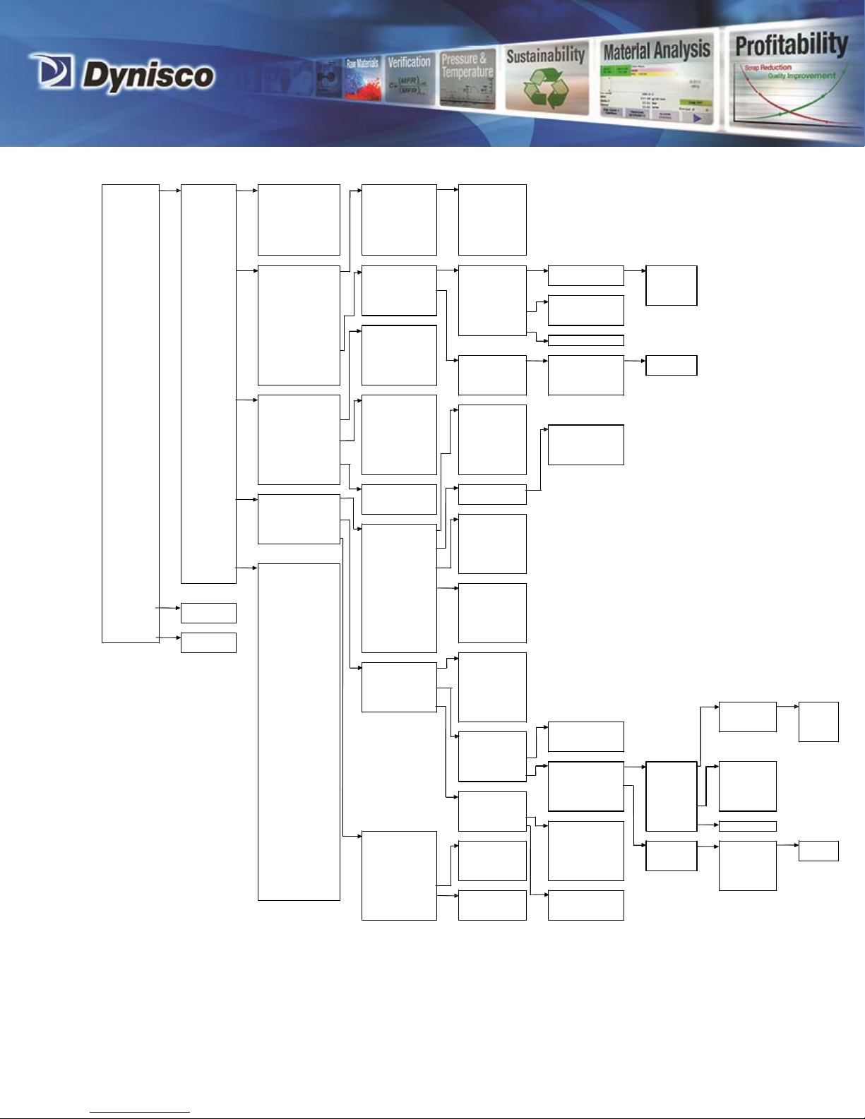
3. PowerontheHARTHandheld.SeeHARTCommandtreeonthefollowingpagefor
reference.
4. FromtheMainMenu:
a. EnterTag(QuickKey1,3,1).
b. Setpressureunits(QuickKey1,3,2),ifrequired.
c. SetURV(QuickKey1,3,3,2)ifoutputturndown(rescaling),isrequired.
d. PerformZeroTrim(QuickKey1,2,5,1,3,1)
5. Verifyloopoutputiszero(4mA).
6. RemoveHARTHandheldfromtheloop.

P/N: 974155 | Rev: 091316 | ECO: 46774
www.dynisco.com
From lab to production,
providing a window into the process
-4-
MENUTREE
1
Device
Setup
1
Process
Variables
1
PV
Pres
2
Pv
%
rnge
3
PV
AO
4
TV
Snout
temp
5
TV
%
rnge
6
TV
AO
7
SV
Elect
temp
1
Alrms
&
Wrnings
2
Max .
Pressure
3
Max .
Electronics
Temperature
4
Max .
Snout
T
emp
EEPROM
Failure
Gage
Failure
Watchdog
Error
Pushbutton
Stuck
Low
Voltage
Outside
URV
LRV
Current
SIM
ON
2
Diag/Service
1
Device
Status
1
Pressure
1
Rerange
1
Enter
values
2
Apply
values
2
Sel
f
T
est
2
T
emperature
3
Maste r
reset
3
Recall
Fact.
T
rim
2
T
rim
analog
output
3
Sensor
trim
1
PV
LRV
2
PV
URV
3
PV
USL
4
PV
LSL
2
PV
Pres
1
Zero
trim
2
Lower
Sensor
Trim
3
Upper
Sensor
Trim
4
Loop
test
5
Calibration
6
Restore
Factory
Defaults
psi
bar
kg/Sqcm
%
MPa
KPa
4
Rcal
1
Rcal
Set
1
T
emperature
Override
2
Trim
analog
Output
1
T
emp
Override
Disable
Enable
2
T
emp
Override
Value
3
Basic
Setup
1
T
ag
2
PV
Unit
3
Range
values
3
T
V
Snout
T
emp
4
Device
Information
5
PV
Damp
1
PV
LRV
2
PV
URV
3
TV
LRV
4
TV
URV
5
PV
LSL
6
PV
USL
7
TV
LSL
8
T
V
USL
1
PV
Pres
2
PV
%
rgne
3
PV
AP
4
TV
Snout
temp
5
TV
%
rnge
6
TV
AO
7
SV
Elect
temp
1
PV
LRV
2
PV
URV
3
PV
USL
4
PV
LSL
4
Detailed
Setup
1
Signal
condition
1
Date
2
Descriptor
3
Message
1
Enter
values
2
Apply
values
2
Output
condition
1
Process
variables
3
Field
Device
Inf.
2
Rerange
5
Review
psi
bar
kg/Sqcm
%
MPa
KPa
4
PV
LRV
1
PV
LRV
2
PV
URV
1
Model
2
Manufacturer
3
Dev
id
4
Distributor
5
Poll
addr
6
Num
req
preams
7
PV
Unit
8
PV
USL
9
PV
LSL
PV
Min
span
PV
Damp
PV
%
rnge
PV
Xfer
fnctn
PV
Rnge
unit
PV
URV
PV
LRV
Lower
Trim
Point
V…
Upper
Trim
Point
V…
TV
C
TV
USL
TV
LSL
TV
%
rnge
TV
Rnge
unit
TV
URV
TV
LRV
Write
protect
Tag
Descriptor
Message
Date
Universal
rev
Fld
dev
rev
Software
rev
Hardware
rev
3
PV
Unit
4
PV
Rnge
unit
5
PV
Min
span
6
PV
Damp
5
PV
URV
1
PV
LRV
2
PV
URV
psi
bar
kg/Sqcm
%
MPa
KPa
7
SV
C
1
Process
variables
2
Analog
output
3
HART
output
1
PV
Pres
2
PV
%
rgne
3
PV
AP
4
TV
Snout
temp
5
TV
%
rnge
6
TV
AO
7
SV
Elect
temp
1
Enter
values
1
PV
AO
2
TV
AO
3
PV
AO
Alrm
typ
4
Loop
test
5
Calibration
Hi
Lo
Hold
last
out
value
2
Apply
values
1
PV
LRV
2
PV
URV
3
PV
USL
4
PV
LSL
1
Pressure
1
Rerange
2
T
emperature
2
T
rim
AO
1
Poll
addr
2
Num
req
preams
3
Burst
mode
4
Burst
option
3
Recall
Fact.
T
rim
3
Sensor
trim
1
Zero
trim
2
Lower
Sensor
Trim
3
Upper
Sensor
Trim
1
T
ag
2
Date
3
Descriptor
4
Message
5
Model
6
Local
Pushbuttons
7
Revision
#'s
8
Final
asmbly
num
9
Dev
id
Disable
Enable
Std
Zero
trim
Of
f
On
Not
used
None
Unknown
Spcl
4
Rcal
1
Rcal
Set
1
T
emp
Override
2
Trim
AO
1
T
emp
Override
Disable
Enable
2
T
emp
Override
Val
1
Universal
rev
2
Fld
dev
rev
3
Software
rev
PV
%
range/current
Process
vars/crnt

P/N: 974155 | Rev: 091316 | ECO: 46774
www.dynisco.com
From lab to production,
providing a window into the process
-5-
TABLEOFCONTENTS
1VERTEXCAREANDHANDLING.............................................................................................................................................6
2GENERAL..............................................................................................................................................................................7
3NOTESONSAFETY..............................................................................................................................................................11
4TECHNICALDATA...............................................................................................................................................................18
5TRANSPORT/DELIVERY/STORAGE......................................................................................................................................23
6INSTALLATIONANDREMOVAL...........................................................................................................................................24
7COMMISSIONING...............................................................................................................................................................32
8UTILIZINGTHEHARTCOMMUNICATIONS..........................................................................................................................35
9MAINTENANCE...................................................................................................................................................................47
10 TROUBLESHOOTING...........................................................................................................................................................49
11 DYNISCOCONTACTINFORMATION....................................................................................................................................50
12 ACCESSORIES......................................................................................................................................................................51
13 APPROVALS/CERTIFICATES.................................................................................................................................................55
14 OUTLINEDRAWINGS..........................................................................................................................................................58

P/N: 974155 | Rev: 091316 | ECO: 46774
www.dynisco.com
From lab to production,
providing a window into the process
-6-
1VERTEXCAREANDHANDLING
BesurethattheportwheretheVertextransducerwillbeinstalledisfreeofallresidualdriedpolymer
frompreviousmanufacturingprocesses(ThisisaccomplishedusingDynisco'smachinewholetooling
kitpartnumber200100).
InapplicationswheretheVertextransducerwillberemovedinbetweenproductionruns,suchasin
themanufactureoffoodproductsormedicaltubing,onlyremovetheVertexwhenthepolymerisat,
ornear,fullprocesstemperature.Thiswillinsurethatyouarepullingthetransducertipfrommolten
conditionsandthereforenotcausinganyunduepullingeffectonthediaphragmthatcouldresultin
damagetothetipandatransducerthatisthenoutofspecification.
Ifthereisresidualpolymermaterialonthetipwhenthesensorisremovedfromaprocessport,
NEVERuseawirebrush,wirewheel,bluntorsharpinstrumenttoremovethepolymer.There
aretwoacceptablewaysofremovingresidualmaterialfromthetipofanypressuresensor:
AfterremovingtheVertexsensor,carefullycleanthediaphragmwithasoftclothorbronzewool
whilethemediumisstillmalleable.Donotattempttocleanthesensorbyheatingsolidifiedpolymer
withatorch.
Asolventbathconsistingofglycolcanbeusedtosoftenthepolymerandimproveremoval.Placethe
tipofthesensorintothesolventbathforaperiodoftimeasdeterminedbywhentheresidual
polymersoftens.Becarefultonotimmersetheelectronicsinthebath.Thisbathcanbeheatedusing
heatelementstoincreaseremovaleffectivenessandshortencycletime.Thenfollowprocedure“a.”
above.
WheninstallingtheVertexsensor,itisimportantnottoover‐torquetheunitintoplace.Theunit
shouldbehandtightened,andthentightenedtotheinstallationtorquespecifiedinsection4.4witha
torquewrench.
Adjustzeroafterinstallingandheatingthemachinetooperatingtemperature.Wherefilled
sensorsaresensitivetoverticalorientationchanges,Vertexissensitivetohorizontalorientation
changesandinstallationtorque.Reducezero‐shiftimpactbysettingzeroandspanafterproperly
installingthesensorintheprocessport.
DonotadjusttheSpanpotentiometerwithRcalactivated.Spanpotentiometeradjustmentsshould
onlybemadewiththeunitinstalledintoacalibratedpressuresourceatFSpressure.

P/N: 974155 | Rev: 091316 | ECO: 46774
www.dynisco.com
From lab to production,
providing a window into the process
-7-
2GENERAL
2.1 IMPORTANTINFORMATION..........................................................................................................................................7
2.2 COPYRIGHT............................................................................................................................................................7
2.3 EXPLANATIONOFICONS................................................................................................................................................8
2.4 ABBREVIATIONS............................................................................................................................................................9
2.5 NAMINGCONVENTION..................................................................................................................................................9
2.6 TRANSMITTERPRINCIPLESOFOPERATION...................................................................................................................9
2.7 CORRECTUSE..........................................................................................................................................................10
2.8 USER’SOBLIGATIONS...................................................................................................................................................10
2.1 IMPORTANTINFORMATION
ThismanualappliestotheVertexbrandsensorproductfamilyonly.Thismanualmustbekeptnearthe
equipmentinareadilyandimmediatelyaccessiblelocationatalltimes.Thecontentofthismanualmust
beread,understoodandfollowedinitsentirety.Thisappliesinparticulartothenotesonsafety.
Followingthesafetyinstructionswillhelptopreventaccidents,defectsandmalfunctions.
Dyniscowillnotbeheldliableforanyinjury,lossordamageresultingfromfailuretofollowthe
instructionsinthismanual.
Iftheproductmalfunctions,inspiteofhavingfollowedtheoperatinginstructions,pleasecontact
customerservicefromourwebsite:www.dynisco.com/contact
2.2 COPYRIGHT
Copyrightlawrequiresthatthismanualbeusedforintendedpurposesonly.
Itisstrictlyforbiddentoallowreproductionofanykind“inwholeorinpart”topersonsoutsideof
Dynisco,withoutapprovalfromDynisco.
HARTisaregisteredtrademarkofHARTCommunicationFoundation.

P/N: 974155 | Rev: 091316 | ECO: 46774
www.dynisco.com
From lab to production,
providing a window into the process
-8-
ATTENTION
2.3 EXPLANATIONOFICONS
Themanualusesiconstoindicateinformationpertainingtosafety:
Riskofdestructionordamagetoequipment,machinesorinstallations
Generaldangertolifeorlimb
Specificdangertolifeorlimb
CEEMCspecificrequirements
ATEXIntrinsicSafetyspecificrequirements
Thesafetyinstructionsareprovidedagainintheindividualsectionsofthemanual.

P/N: 974155 | Rev: 091316 | ECO: 46774
www.dynisco.com
From lab to production,
providing a window into the process
-9-
2.4 ABBREVIATIONS
Thefollowingabbreviationsareused:
EMC ElectromagneticCompatibility
ESD Electrostaticdischarge
Exc Excitation
mA milliampere
mV/V millivoltpervolt(astandardpressuresensoroutput)
Pwr Power
Sig Signal
T/C Thermocouple
in‐lbsinchPounds(torque)
BSL BestStraightLine
DD DeviceDescriptor
EEPROM ElectricallyErasableProgrammableReadOnlyMemory
FS FullScale
HARTHighwayAddressableRemoteTransducer
LRV LowerRangeValue
PT PressureTransmitter
PV PrimaryVariable(Pressure)
RTD ResistanceTemperatureDetector(Averyaccuratetemperaturesensor)
SV SecondaryVariable(ElectronicsTemperature)
TV TertiaryVariable(SnoutTemperature)
URV UpperRangeValue
Watchdog Aninternalmonitorfortheelectronics
2.5 NAMINGCONVENTION
Vertex VertexBrandPressureSensor
2.6 TRANSMITTERPRINCIPLESOFOPERATION
Themechanicalsystemconsistsofadiaphragmlocatedonthesensortip.Thediaphragmisa
metalplatedesignedtodeflectinresponsetopressureappliedtothetip.Thediaphragmisin
directcontactwiththefluidmedia(gasorliquid)tobemeasuredanditspurposeistoconvertthe
pressureofthemediatomechanicaldeflection.
Insidethesensor,thediaphragmplatedeflectionisconvertedtoamVelectricalsignal.Electronic
circuitryperformsthesignalconditioningnecessarytoconvertthatsignalintotheoutput(mV/Vor
4‐20mAorvoltage).
AnoptionalJorK‐thermocoupleprocesstemperatureoutputisalsoavailable.Theseoutputsare
fromacustomeraccessiblethermocoupleincludedinthesnouttip.

P/N: 974155 | Rev: 091316 | ECO: 46774
www.dynisco.com
From lab to production,
providing a window into the process
-10-
Anoptionalshuntcalibration(Rcal)outputisalsoavailable.Rcalisamethodofgeneratinganelectrical
outputtomatchtheelectricaloutputthatwouldbegiveninresponsetoanappliedpressure.Rcalis
normallysetto80%FSsothatallsimilarsensorscalibrateatthesamepointtofacilitate
interchangeability.
Rcaltracesitsroutestostraingagetransducers.Instraingagetechnology,Rcalisnormallyaresistor
insertedintotheWheatstonebridgetooffsetitsoutputasif80%pressurewasapplied.IntheVertex
brandsensor,Rcalisanelectricalsimulationof80%pressureandiscreatedintheelectronics
circuitry.DonotadjusttheSpanpotentiometerwithRcalactivated.Spanpotentiometeradjustments
shouldonlybemadewiththeunitinstalledintoacalibratedpressuresourceatFSpressure.
2.7 CORRECTUSE
WhenusingaVertexbrandsensorasasafetycomponentinaccordancewiththeECMachine
Directive,AnnexIIc,theequipmentmanufacturermusttakeanynecessaryprecautionstoensurethat
malfunctionofthePTcannotcausedamageorinjury.
Forinstallationinexplosivegasatmospheresthedevicemustbeinstalledinaccordancewith
EuropeaninstallationguidelinesEN60079‐14.Forcategory1(zone0)installations,overvoltage
protectionoftheelectricalconnectionsshallbeinaccordancetoEN60079‐14.
WhenplanningmachineryandusingoneofthesensorsfromtheVertexbrandsensorFamily,follow
thesafetyandaccidentpreventionregulationsthatapplytoyourapplication,suchas:
EN60204,Electricalequipmentinmachines
EN12100,Machinesafety,generaldesignguidelines
DIN57100Part410,Protectionagainstelectricshock
EN60079‐0Explosiveatmospheres‐GeneralRequirements
EN60079‐11Explosiveatmospheres‐IntrinsicallySafeApparatus
EN60079‐26SpecialRequirementsforEPLGa
2.8 USER’SOBLIGATIONS
Theoperatororownerofthelargeroverallsystem,e.g.amachine,isresponsibleforfollowingthe
safetyandaccidentpreventionregulationsthatapplytothespecificapplication.

P/N: 974155 | Rev: 091316 | ECO: 46774
www.dynisco.com
From lab to production,
providing a window into the process
-11-
3NOTESONSAFETY
3.1 RISKOFDESTRUCTIONORDAMAGETOEQUIPMENT,MACHINE,ORINSTALLATION...............................11
3.2 GENERALDANGERTOLIFEORLIMB..........................................................................................................11
3.3 CEEMCSPECIFICREQUIREMENTS.............................................................................................................12
3.3.1 mV/Vanalogoutput...................................................................................................................................12
3.3.2 mAanalogoutput.......................................................................................................................................12
3.3.3 Voltageanalogoutput................................................................................................................................12
3.4 ATEXINTRINSICSAFETYAPPROVALSPECIFICREQUIREMENTS..................................................................13
3.1 RISKOFDESTRUCTIONORDAMAGETOEQUIPMENT,MACHINE,ORINSTALLATION
Avoidapplyingtransverseloadstotherigidportionofthesensorprotrudingfromthe
equipment/mountingport.
TheVertexbrandsensorisanESDsensitivecomponent.Electrostaticdischargemaydamagethe
Vertexbrandsensor.TakeESDprecautionswhencontactinginput/outputpinsorleadwires.
3.2 GENERALDANGERTOLIFEORLIMB
Theoperatororownerofthelargeroverallsystemisresponsibleforfollowingthesafetyand
accidentpreventionregulationsthatapplytothespecificapplication.
Dyniscowillnotbeheldliableforanyinjury,lossordamageresultingfromfailuretofollowthe
instructionsinthismanual.
Electricalshockcanresultindeathorseriousinjury.Avoidcontactwiththeleadsandterminals.
Highvoltagethatmaybepresentonleadscancauseelectricalshock.
MountingandelectricalconnectionofthePTmustbedonebyspecialistswithEMCtraining,
followingallapplicableregulations,andinpressure‐less,voltage‐free,intrinsicallysafecondition
withthemachineswitchedoff.Themachinemustbesecuredagainstbeingswitchedbackon!
Deviationofthesupplyvoltagefromthevaluegiveninthetechnicalspecifications,orreverse
polarity,candamagethepressuretransmitterandcausemalfunctionsthatcanposeariskof
explosion.
SeveralconfigurationsofVertexaredesignedandapprovedforuseinhazardousclassifiedareas.
Unitsintendedforinstallationintheseareasmustbeartheapplicableapprovalagencylabel.
ATTENTION

P/N: 974155 | Rev: 091316 | ECO: 46774
www.dynisco.com
From lab to production,
providing a window into the process
-12-
3.3 CEEMCSPECIFICREQUIREMENTS
Thehousingofthetransmittermustbereliablyconnectedtothelocalequipotentialbonding
system.Thehousingiselectricallybondedtotheprocessequipmentthroughtheprocess
connection.
3.3.1 mV/Vanalogoutput
AllmV/VPTsneedtohaveashieldconnectiontogroundattheprocessconnectionand
instrumentationends.
AllmV/VPTswithconduitfitting(electricalconnectioncodes6*C)haveaconnectionbetweenthe
conduitcableshieldandthecaseinternallyattheconduitfitting.
FormV/VPTswithconnectorfitting,itisthecustomer’sresponsibilitytoinsurethereisa
connectionbetweentheconnectorcableshieldandthematingconnector.
3.3.2 mAanalogoutput
AllmAPTsneedtohaveashieldconnectiontogroundattheprocessconnectionend.
ForATEXISapprovedmAPTs,onlyconnectthecaseand/orshieldleadstogroundatthe
instrumentationendifahighlevelofassuranceexiststhatthereispotentialequalizationbetween
eachendofthecircuittoavoidthedangerofcirculatingfaultcurrents.
AllmAPTswithconduitfitting(electricalconnectioncodes3*C,5*C)haveconnectionsbetween
theconduitcableshieldandcaseleadtothecaseinternallyattheconduitfitting.
FormAPTswithconnectorfitting,itisthecustomer’sresponsibilitytoinsurethereisaconnection
betweentheconnectorcableshieldandthematingconnector.
3.3.3 Voltageanalogoutput
AllVPTsneedtohaveashieldconnectiontogroundattheprocessconnectionend.
AllVPTswithconnectorfitting,itisthecustomer’sresponsibilitytoinsurethereisaconnection
betweentheconnectorcableshieldandthematingconnector.

P/N: 974155 | Rev: 091316 | ECO: 46774
www.dynisco.com
From lab to production,
providing a window into the process
-13-
3.4 ATEXINTRINSICSAFETYAPPROVALSPECIFICREQUIREMENTS
ThissectiononlyappliestoPTswithATEXISoption.
EquipmentMarkingInformation
ModelNumber:(PleasereviewthecalibrationsheetthatcamewithyourPTshipment)Range:
(PleasereviewthecalibrationsheetthatcamewithyourPTshipment)Input:
24VDC
Output:4‐20mA
Stem:(PleasereviewthecalibrationsheetthatcamewithyourPTshipment)Flex:
(PleasereviewthecalibrationsheetthatcamewithyourPTshipment)
ATEXApprovalMarkings:
ManufacturerAddress:DyniscoInstrumentswww.dynisco.comFranklin,MA02038
Instructionsforsafeputtingintoservice&installation
Afterinstallingthedevice,butbeforeoperatingthedevice,theusermustcheckthatthecomplete
installationandwiringisintrinsicallysafe.Specialcaremustbetakentoinsurethatthepowersupply
isacertifiedapparatus.
Alsoreviewcontroldrawing000612,whichisincludedattheendofthissection.
Instructionsforsafeuse
Reviewcontroldrawing000612,whichisincludedattheendofthissection.
Maintenance(servicingandemergencyrepair),assembly,dismantlingandadjustment
ThePTdoesnotrequireanyinstructionsforsafemaintenance,assembly,dismantlingoradjustment
Safeelectricalandpressureparametersandmaximumsurfacetemperaturelimits
MaximumallowedPTpressure:(Pleasereviewthecalibrationsheetthatcamewithyour
PTshipment)Alsoreviewcontroldrawing000612,whichisincludedattheendofthis
section.
SpecialConditionsofuse
Reviewcontroldrawing000612,whichisincludedattheendofthissection.

From
provi
d
lab to produ
c
d
ing a windo
w
c
tion,
w
into the pro
c
P/N: 9
7
c
ess
7
4155 | Re
v
www
.
v
: 091316 |
.
dynisco.co
m
-14-
ECO: 46774
m

From
provi
d
lab to produ
c
d
ing a windo
w
c
tion,
w
into the pro
c
P/N: 9
7
c
ess
7
4155 | Re
v
www
.
v
: 091316 |
.
dynisco.co
m
-15-
ECO: 46774
m

P/N: 974155 | Rev: 091316 | ECO: 46774
www.dynisco.com
From lab to production,
providing a window into the process
-16-

P/N: 974155 | Rev: 091316 | ECO: 46774
www.dynisco.com
From lab to production,
providing a window into the process
-17-

P/N: 974155 | Rev: 091316 | ECO: 46774
www.dynisco.com
From lab to production,
providing a window into the process
-18-
4TECHNICALDATA
4.1 MODELCODEBREAKDOWN............................................................................................19
4.2 PERFORMANCECHARACTERISTICS...............................................................................19
4.2.1 ACCURACY.........................................................................................................................19
4.2.2 RESOLUTION.....................................................................................................................19
4.2.3 REPEATABILITY................................................................................................................19
4.2.4 OVERLOADPRESSURE(MAXPRESSUREWITHOUTINVALIDATINGSPECIFIED
ACCURACY)........................................................................................................................19
4.2.5 BURSTPRESSURE.............................................................................................................19
4.2.6 RESPONSETIME...............................................................................................................19
4.3 ELECTRICALDATA...........................................................................................................20
4.4 INSTALLATIONSPECIFICATIONS....................................................................................20
4.5 TEMPERATURESPECIFICATIONS...................................................................................20
4.6 INSTALLATIONINFLUENCE............................................................................................21
4.7 TEMPERATUREINFLUENCE............................................................................................21
4.8 EMCREQUIREMENTS.......................................................................................................22
4.9 MATERIALS.......................................................................................................................22
4.10 ENVIRONMENTALPROTECTIONTOANSI/IEC‐60529&ANSI/NEMA‐250................22
4.11 WEIGHT.............................................................................................................................22
4.12 DIMENSIONS.....................................................................................................................22

P/N: 974155 | Rev: 091316 | ECO: 46774
www.dynisco.com
From lab to production,
providing a window into the process
-19-
4.1 MODELCODEBREAKDOWN
PleaseseeVertexdatasheetonwww.dynisco.com
4.2 PERFORMANCECHARACTERISTICS
4.2.1ACCURACY
Accuracyisdefinedascombinederrorexpressedasapercentageoffullscale(%F.S.)outputbasedon
thefollowingstandardconfigurations/conditions:
1) BestStraightLine%FSasperISA‐37.3
2) Electronicsatambient(+20C).
3) DymaxCoatedInconel718
Diaphragm
Consultfactoryfornon‐standardconfigurations.
RangeOptionAccuracy(%ofF.S.O.)
250–10,000PSIMM1±0.25
250–10,000PSIHH1(mAonly)±0.15
4.2.2 RESOLUTION
±0.035%fullscale@50%FS(averageresolution)
4.2.3 REPEATABILITY
±0.10%ofFS
4.2.4 OVERLOADPRESSURE(MAXPRESSUREWITHOUT
INVALIDATINGSPECIFIEDACCURACY)
1.5xFS
4.2.5 BURSTPRESSURE
> 5xFS
4.2.6 RESPONSETIME
4mSrisetime(0‐63%)

P/N: 974155 | Rev: 091316 | ECO: 46774
www.dynisco.com
From lab to production,
providing a window into the process
-20-
4.3 ELECTRICALDATA
OutputSignal2‐wire4‐20mAormV/Vorvoltage
mV/VSpecifications3.3mV/V
mASpecifications4‐20mA,endpointssetbyzero/spanactuators
voltageSpecifications0‐5V,0‐10V,1‐6V,or1‐11Vsetbyzero/spanactuatorsT/C
Specifications+/‐2°C
CurrentConsumption<30mA
SupplyVoltage4‐20mAorvoltage:16‐36V(Note:sensorincorporatesovervoltage
protectionandreversepolarityprotectionandwillnotoperateif
inputsarereversed).
mV/V:10Vrecommended,10‐12V
4.4 INSTALLATIONSPECIFICATIONS
InstallationTorque250in‐lbs.recommended
300in‐lbsmax(Transducersinstalledatamountingtorqueabove
thismaydamageunitandmaybedifficulttoremoveevenwhen
anti‐seizecompoundisapplied).
RemovalTorqueDonotexceed500in‐lbs
Flexbendradius1inch(25mm)minimum
4.5 TEMPERATURESPECIFICATIONS
ElectronicsHousing
OperatingTemperatureRange‐58to+185°F(‐50to+85°C)
CompensatedTemperatureRange+68to+150°F(+20to+65°C)
FlexandTransition
OperatingTemperatureRange‐58to+300°F(‐50to+150°C)
CompensatedTemperature Range+68to+300°F(+20to+150°C)
RigidSnout
OperatingTemperatureRange‐58to+750°F(‐50to+400°C)
CompensatedTemperatureRange+68to+660°F(+20to+350°C)
Table of contents
Other Dynisco Accessories manuals
Popular Accessories manuals by other brands

System Sensor
System Sensor RA400Z Installation and maintenance instructions

ooma
ooma motion sensor quick start guide

The Pure Company
The Pure Company Aromatherapy Diffuser manual

Lanbe
Lanbe SP-1215 user manual

Fire-Lite Alarms
Fire-Lite Alarms H355 Installation and maintenance instructions

Orno
Orno OR-GB-438 quick start guide

ALERTON
ALERTON BACtalk Microset II Installation & operation guide

Pragma
Pragma AXI Beachwagon Cooler instruction manual

ESI
ESI GIGAPORT HD user guide

IFM Electronic
IFM Electronic efector 600 OWF installation instructions

Covidien
Covidien Nellcor MAXI Instructions for use

Budweiser
Budweiser RED LIGHT instruction manual