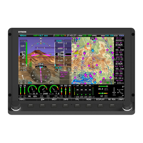
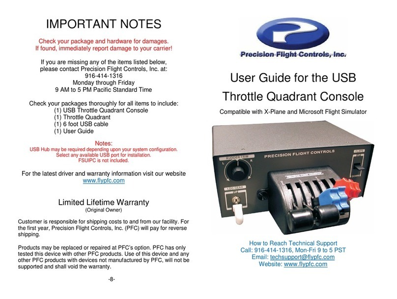
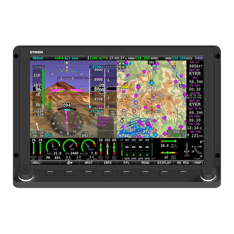
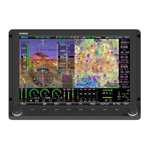
Dynon Avionics SkyView HDX Instruction sheet

SkyView HDX System
Configuration Manual
Cessna Models 172 F-S
103527-000
Revision A
4/17/2019
Copyright © 2019 by Dynon Avionics, Inc.
Dynon grants third parties’ permission to print this document


SkyView HDX System Configuration Manual - Cessna Models 172 F-S, Revision A
Page | i
Contact Information
Dynon Avionics, Inc.
19825 141st Place NE
Woodinville, WA 98072
Phone: 425-402-0433
Business Operations: 8:00 AM - 5:00 PM (Pacific Time) Monday - Friday
Technical Support Operations: 7:00 AM - 4:00 PM (Pacific Time) Monday - Friday
Fax: 425-984-1751
Web: www.dynoncertified.com
Copyright
©2019 Dynon Avionics, Inc. All rights reserved. No part of this manual may be reproduced, copied, transmitted, disseminated or stored in any
storage medium, for any purpose without the express written permission of Dynon Avionics. Dynon Avionics hereby grants permission to
download a single copy of this manual and of any revision to this manual onto a hard drive or other electronic storage medium to be viewed for
personal use, provided that such electronic or printed copy of this manual or revision must contain the complete text of this copyright notice and
provided further that any unauthorized commercial distribution of this manual or any revision hereto is strictly prohibited.
Information in this document is subject to change without notice. Dynon Avionics reserves the right to change or improve its products and to
make changes in the content without obligation to notify any person or organization of such changes. Visit the Dynon Avionics website
(www.dynonavionics.com) for current updates and supplemental information concerning the use and operation of this and other Dynon Avionics
products.

Page | ii
SkyView HDX System Configuration Manual - Cessna Models 172 F-S, Revision A
Revision History
REV
CHANGE
ECO
DATE
A
Initial Release for Cessna Models 172, F-S
319097
4/17/2019

SkyView HDX System Configuration Manual - Cessna Models 172 F-S, Revision A
Page | iii
Reference Documents
Document
102949-003 Dynon SkyView HDX Pilot’s User Guide
103261-000 Dynon SkyView HDX Installation Manual for AML STC SA02594SE
FAA Advisory Circular 43.13 Acceptable Methods, Techniques and Practices- Aircraft
Inspection and Repair.
103488-000 Wiring Diagram, Typical HDX Dual Display
103527-000 - SkyView HDX System Configuration - Cessna 172F-Q.dfg
103527-000 - SkyView HDX System Configuration - Cessna 172R-S.dfg

Page | iv
SkyView HDX System Configuration Manual - Cessna Models 172 F-S, Revision A
Table of Contents
1Introduction............................................................................................... 1
2System Software....................................................................................... 2
3Configuring SkyView HDX using the Setup Menu System .................... 3
3.1 SETUP Menu Entry...................................................................................................... 3
3.2 SETUP Menu................................................................................................................ 3
3.3 Local Display Setup Menu Configuration.................................................................... 10
3.4 PFD Setup Menu Configuration.................................................................................. 12
3.5 EMS Setup Menu Configuration................................................................................. 15
3.6 MAP Setup Menu Configuration................................................................................. 16
3.7 Autopilot Setup Menu Configuration........................................................................... 16
3.8 Transponder Setup Menu Configuration..................................................................... 19
3.9 Traffic Setup Menu Configuration............................................................................... 20
3.10 COM Radio Setup Menu Configuration...................................................................... 20
3.11 Hardware Calibration Menu Configuration.................................................................. 20

SkyView HDX System Configuration Manual - Cessna Models 172 F-S, Revision A
Page | 1
1 Introduction
This document provides guidance to correctly configure the SkyView HDX system when installed
in a Cessna 172F-S model aircraft.
This document assumes that SkyView and its components have been wired in accordance with
document 103488-000 Wiring Diagram, Typical HDX Dual Display.
Dynon provides an associated configuration file which should be loaded before beginning the
configuration process. These files are available for download. Choose the one best for your
aircraft:
103527-000 - SkyView HDX System Configuration - Cessna 172F-Q.dfg
103527-000 - SkyView HDX System Configuration - Cessna 172R-S.dfg
These files, when loaded in an airplane equipped with the Dynon SkyView HDX system, will:
•Configure all sensors to the factory delivered values appropriate for the Cessna 172. Edits
may be required for airplanes modified with other engines. This would be accomplished
manually using the Screen Layout Editor menu.
•Locate all widgets in the EMS Bottom Band and 50% display to match the FAA Human
Factors assessed layout. This would be otherwise accomplished manually using the
Screen Layout Editor menu.
•Configure the optional autopilot servos with the FAA approved values. This would
manually be accomplished using the Autopilot Setup menu. Do not be concerned about
loading this file if you do not have an autopilot installed, loading these values will not
cause any harm.
Load the configuration file before you begin the configuration described in this manual. This will
reduce the effort required.
The configuration manual and data file assume that the airplane is as delivered by the
manufacturer and has not been modified in any way. Any system or performance differences will
need to be manually configured after the configuration file has been loaded.
The configuration file can be downloaded to a USB drive and then loaded into SkyView following
the guidance provided in Section Error! Reference source not found..
Where specific configuration selections or entries are required for certification, complete
instructions will be provided. The remaining configuration opportunities are considered
owner/operator-controlled options. Installers may need to consult with the owner/operator in
order to make the correct configuration selections.
Page | 2
SkyView HDX System Configuration Manual - Cessna Models 172 F-S, Revision A
2 System Software
The System Software menu does not have any settings requiring configuration, but Dynon does
provide configurations files that can be loaded into SkyView using the System Software menu.
These files will accomplish much of the systems configuration settings covered by this manual.
These files can be downloaded to a USB drive and then loaded onto SkyView using the LOAD
FILES wizard.
The Systems Software menu will not be active unless a USB Drive is mounted to the display
USB port.
The SYSTEM SOFTWARE Menu contains links to the following wizards:
•UPGRADE SYSTEM SOFTWARE. –Use this wizard to update Software on your
SkyView system.
•LOAD FILES –Use this wizard to load files such assettings or configuration files or delete
files from the USB flash drive.
•EXPORT SETTINGS –Use this wizard to export the settings on your SkyView system to
a USB flash drive.
•EXPORT USER DATA LOGS –Use this wizard to export user data logs in human-
readable CSV format.
•EXPORT USER WAYPOINTS –Use this wizard to export the User Waypoints that are
currently stored in your SkyView system.
•EXPORT DYNON DIAGNOSTIC FILE –This specialized data log can only be interpreted
by Dynon Avionics personnel; there is no data in it that can be interpreted by SkyView
pilots. Dynon Avionics Technical Support may request this log during troubleshooting,
especially for issues related to AP performance. Note that this log is very big –over 500
MB –and takes minutes to save to a USB flash drive. Unless directed to export this log
by Dynon Avionics, there is no reason to do so

SkyView HDX System Configuration Manual - Cessna Models 172 F-S, Revision A
Page | 3
3 Configuring SkyView HDX using the Setup Menu System
The following is an overview of each of the system configuration menus, their sub-menus, and
the information that must be selected or inputted to match the certificated configuration.
3.1 SETUP Menu Entry
The SkyView HDX Display features a row of eight buttons across the bottom below the screen.
These buttons are numbered 1-8 from left to right. Knobs are provided to allowscrolling vertically
or horizontally as appropriate for the menu. In addition, the knobs can be pushed to make
selections. See Figure 1.
Figure 1 Display Controls and Control Labels
Simultaneously pressing and holding buttons 7 and 8 will open one of the setup menus. There
are two setup menus: The Setup Menu and the In-Flight Setup Menu. If the airspeed is zero,
the Setup Menu will open. If the airspeed is greater than zero, the In-Flight Setup Menu will
open.
You may also access the Setup Menu from the In-Flight Setup Menu by using the ENTER FULL
SCREEN SETUP MENU option.
3.2 SETUP Menu
The setup menu provides access to the following system configuration menus:
•SYSTEM SOFTWARE
•SYSTEM SETUP •LOCAL DISPLAY SETUP
•PFD SETUP

Page | 4
SkyView HDX System Configuration Manual - Cessna Models 172 F-S, Revision A
•EMS SETUP
•MAP SETUP
•AUTOPILOT SETUP
•TRANSPONDER SETUP
•TRAFFIC SETUP
•ADS-B STATUS
•COM RADIO SETUP
•HARDWARE CALIBRATION
When a setting within one of the setup menus or sub-menus are changed in a SkyView display,
the change is synchronized to other SkyView displays, when installed. It is not necessary to
make the change in every display.
3.2.1 System Setup Menu Configuration
The System Setup menu contains menus and pages related to the entire SkyView system. The
following list of menus can be found in System Setup:
•SKYVIEW NETWORK SETUP
•WI-FI SETUP
•SERIAL PORT SETUP
•AUDIO SETUP
•AIRCRAFT INFORMATION
•MEASUREMENT UNITS
•TIME
•ARINC-429
•SCREEN LAYOUT SETUP
•PRIMARY COM
•DISPLAY COM IN TOP BAR
•DATA LOG SETUP
The very first thing that requires configuration is the insertion of the aircraft’s registration number.
This is accomplished using the Aircraft Information menu. Refer to Section 3.2.6
Some of these menus have specific configuration requirements, while others have optional
configurations that can be set to an individual preference, and other menus simply display
information. The sections thatfollow will provide an overview of the information and configuration
options contained within the menus, unless the menu has specific requirements. If specific
configurations are required, instructions on how to configure the menu will be included.
3.2.2 SkyView Network Setup Menu
Enter this menu to configure your SkyView network or to check on network status (i.e., display
important SkyView module information).
Any time a SkyView Network Module is added, replaced with another of the same type, or
removed from the SkyView network, the network must be configured. This menu allows you to
access the following pages:
•Networks Status –This page provides a list of all the connected SkyView modules by
model name. it also provides the serial number for each module, as well as the status of
each module.

SkyView HDX System Configuration Manual - Cessna Models 172 F-S, Revision A
Page | 5
•Network Configure wizard –This page will allow you to “Configure” the network, which is
a process that the system uses to look for changes on the network, such as:
oA module has been replaced, causing a serial number to change,
oA module has been added to the network,
oA module has been removed from the network.
The network must be configured any time a module is replaced, added, or removed from
the network.
•Force Network Load wizard –When the above Configure operation is accomplish, only
the software that has changed gets pushed out to the modules from SkyView. The Force
Network Load operation replaces each of the module’s software with a fresh copy. This
is done whenever software corruption is thought to be the source of misbehavior.
Figure 2 SYSTEM SETUP Menu
3.2.3 WI-FI Setup Menu
The WI-FI setup menu configures a wireless network to allow other wireless computing
devices to communicate with SkyView. Requires a WI-FI antenna connected to a USB adapter
connected to SkyView.
3.2.4 Serial Port Setup Menu
The Serial Port Setup menu controls the configuration of up to 5 serial ports (see Figure 3) can
be configured to transmit and/or receive information from RS232 capable devices. To configure
in accordance with the Dynon provided Typical HDX Dual Display Wiring Diagram, serial ports
1, 2 and 5 should be configured as shown in Figure 4, Figure 5, and Figure 6:

Page | 6
SkyView HDX System Configuration Manual - Cessna Models 172 F-S, Revision A
Figure 3 SERIAL PORT SETUP Menu
Figure 4 SERIAL PORT 1 Configuration

SkyView HDX System Configuration Manual - Cessna Models 172 F-S, Revision A
Page | 7
Figure 5 SERIAL PORT 2 Configuration
Figure 6 SERIAL PORT 5 Configuration
3.2.5 Audio Setup Menu
The AUDIO SETUP menu controls the behaviors of all the SkyView audio annunciations. As
an initial starting point, configure each item according to Figure 7.

Page | 8
SkyView HDX System Configuration Manual - Cessna Models 172 F-S, Revision A
Figure 7 AUDIO SETUP Configuration
3.2.6 Aircraft information Menu
Enter this page to record important information regarding your aircraft. Specifically, enter the tail
number of your aircraft –it is used to create unique SkyView configuration files. It is also used
for other purposes. Note that for US planes, the leading N is a required part of the TAIL
NUMBER. The TAIL NUMBER should not include dashes (-) or spaces.
NOTE: Ensure that 0 is not used in place of O, and O is not used in place of 0.
Examples:
•Correct: N12AB

SkyView HDX System Configuration Manual - Cessna Models 172 F-S, Revision A
Page | 9
•Incorrect: N-42SV, N 42SV, or 42SV
3.2.7 Measurement Units Menu
Enter this page to configure displayed units (e.g., feet or meters). Configure the Measurement
Units as desired.
3.2.8 Time Menu
First, configure the Top Bar to display time in SETUP MENU > LOCAL DISPLAY SETUP >
TOP BAR SETUP > TIME: and choose either ZULU or LOCAL time.
Return to the SYSTEM SETUP > TIME menu and adjust your preferred offset from the time
currently displayed on the Top Bar.
3.2.9 ARINC-429 Menu
This menu configures the SV-ARINC-429 module, if installed. The SV-ARINC-429 provides an
interface through which an external IFR Navigator can communicate with SkyView. An SV-
ARINC-429 module must be configured in the SkyView network for this menu item to become
enabled.
3.2.10 Screen Layout Setup Menu
Enter this page to configure the availability of the PDF Page, Engine Page, and Map Page on
this display and throughout the system (when more than one display is installed). Configure
the settings according to Figure 8.
Figure 8 SCREEN LAYOUT SETUP Configuration
3.2.11 Primary COM Menu

Page | 10
SkyView HDX System Configuration Manual - Cessna Models 172 F-S, Revision A
Select the desired COM radio to be displayed on the Top Bar and receive a frequency setting
when the APT→COM button is pushed in the MAP MENU. If only one COM radio is installed,
this must be set. If two COM radios are installed, only one can be displayed on the Top Bar and
receive a frequency setting when the APT→COM button is pushed in the MAP MENU.
Select your SV-COM-PANEL to be the Primary COM, and select YES for DISPLAY COM IN
TOP BAR, as shown in Figure 9.
Figure 9 PRIMARY COM Configuration
3.2.12 Display COM in top Bar Menu
Selects whether, or not, frequencies, PTT status, etc. from the COM radio (selected in PRIMARY
COM, above) is displayed (see Figure 9).
3.2.13 Data Log Setup Menu
Enter this page to configure the recording frequency of SkyView’s internal data logging feature,
or to clear recorded data. See the User Data Logs Appendix for further information about user
data logs. Configure the Data log as desired.
3.3 Local Display Setup Menu Configuration
This menu contains menus and pages related to the individual SkyView display on which this
menu is displayed. These settings can be different on one display from another display.
•INSTALLED DATABASES
•DISPLAY HARDWARE INFORMATION
•BRIGHTNESS SETUP
•TOP BAR SETUP
•GPS FIX STATUS

SkyView HDX System Configuration Manual - Cessna Models 172 F-S, Revision A
Page | 11
•BATTERY BACKUP (SV-BAT-320) STATUS
•LICENSE
•VIDEO INPUT
•TOUCH SETUP
Some of these menus have specific configuration requirements, while others have optional
configurations that can be set to an individual preference, and other menus simply display
information. The sections thatfollow will provide an overview of the information and configuration
options contained within the menus, unless the menu has specific requirements. If specific
configurations are required, instructions on how to configure the menu will be included.
Configure the menus that follow as described:
3.3.1 Installed Databases
The Installed Databases page provides status of the installed databases and charts software.
Any software databases that have expired will be identified in yellow. Refer to Figure 10.
Figure 10 Installed Databases Page
3.3.2 Display Hardware Information
The Display Hardware Information page provides information related to the display hardware
itself, its software, and its back up battery if connected.
3.3.3 Brightness Setup
The Brightness Setup page provides controls to adjust the displays brightness.
3.3.4 Top Bar Setup
Top Bar Setup allows the time to be set to indicate Zulu or Local time.

Page | 12
SkyView HDX System Configuration Manual - Cessna Models 172 F-S, Revision A
3.3.5 GPS Fix Status
GPS Fix Status provides information about the quality of the GPS signals being received, and
the number of satellites in view.
3.3.6 Battery Backup (Sv-Bat-320) Status
Battery Backup Status page provides information about the backup battery, if connected.
3.3.7 License
The License page provides a summary of the licenses installed in SkyView.
3.3.8 Video Input Setup
The Video Input Setup configures the video display on SkyView, providing a video adapter is
connected to a SkyView USB port.
3.3.9 Touch Setup
Touch Setup provides configuration options and status information regarding the display’s
touch system.
3.4 PFD Setup Menu Configuration
This menu contains menus and pages related to Primary Flight Display page and data source
(ADAHRS module).
•ADAHRS SOURCE SELECTION
•FLIGHT ANGLE PITCH ADJUST
•AIRSPEED LIMITATIONS
•VERTICAL SPEED SCALE
•G METER
•FLIGHT PATH MARKER
•EXTREME PITCH WARNING
•ANGLE OF ATTACK
•ALTITUDE BUG ALERTER
•CAPTURE BAND
•DEVIATION BAND
•PFD MODE
•BARO MISMATCH WARNING
Some of these menus have specific configuration requirements, while others have optional
configurations that can be set to an individual preference, and other menus simply display
information. The sections thatfollow will provide an overview of the information and configuration
options contained within the menus, unless the menu has specific requirements. If specific
configurations are required, instructions on how to configure the menu will be included.
Configure the menus that follow as described:

SkyView HDX System Configuration Manual - Cessna Models 172 F-S, Revision A
Page | 13
3.4.1 ADAHRS Source Selection
This page has a list of all configured SkyView ADAHRS modules and their respective status.
The ADAHRS module used as the PFD’s source of data can be selected.
3.4.2 Flight Angle Pitch Adjust
This page allows you to adjust the displayed pitch of the waterline symbol (aircraft reference on
the attitude indicator) to compensate for the aircraft’s attitude in level flight. That attitude can
change depending on aircraft loading. This setting is not intended to compensate for an
ADAHRS module that is not installed correctly.
3.4.3 Airspeed Limitations
Enter this menu to configure the V-speeds and specify optimal flight parameters, such as the
best angle of climb speed, the best rate of climb speed, and the optimum maneuvering speed.
These speeds will generate markers and color ranges on the speed tape.
Configure the Airspeed Limitations according to speeds provided in the Aircraft Flight Manual
(AFM) that came with your airplane, or the Aircraft Flight Manual Supplement(s) (AFMS) that
came with any STC modifications that have been made to your aircraft. See Figure 11 as an
example.
Figure 11 Airspeed Limitations Configuration
3.4.4 Vertical Speed Scale
Enter this page to select configuration options of the vertical speed tape's scale. Configure as
desired.
3.4.5 G Meter
Enter this page to configure G values that will cause the G Meter to be automatically displayed
when exceeded; to set the yellow/red cautionary color ranges of the G meter; and whether the
max/min recorded G’s are reset at each SkyView boot-up. Configure the G meter as desired.

Page | 14
SkyView HDX System Configuration Manual - Cessna Models 172 F-S, Revision A
3.4.6 Flight Path Marker
Enter this page to enable/disable display of the flight path marker. Configure the Flight Path
marker as desired. Dynon recommends that you enable the Flight Path Marker as it is a valuable
safety enhancing tool.
3.4.7 Extreme Pitch Warning
Enter this page to enable/disable display of the extreme pitch warning indicators. Dynon
recommends that you enable the Extreme Pitch Warning as it is a valuable safety enhancing
tool.
3.4.8 Angle of Attack
Enter this page to enable/disable display of the Angle of Attack indicator. The Angle of Attack
indicator requires the angle of attack sensor to be installed.
3.4.9 Altitude Bug Alert
Enter this page to configure the altitude aural alert when you are approaching or departing the
altitude set in the ALT bug. Configure as desired.
3.4.10 Capture Band
When the altitude of the aircraft flies within this range of feet/meters of the altitude bug (when
displayed), SkyView will announce “approaching altitude” aurally (if audio output is configured).
Configure the Capture band as desired.
3.4.11 Deviation Band
When the altitude of the aircraft climbs above or descends below the altitude bug by the range
of feet or meters set here, SkyView will announce “departing altitude” aurally (if audio output is
configured). Configure the Deviation band as desired.
3.4.12 PFD Mode
On the Primary Display (if more than one display is installed), as depicted in Figure 12, the PFD
Mode menu shall have the:
•LAYOUT configuration set to ALWAYS EFIS, which means that the EFIS layout will
always be displayed.
•WIDE ANGLE VIEW configuration set to ALWAYS NORMAL, which means the normal
view of the horizon on the PFD will always be displayed.
Other manuals for SkyView HDX
4
Table of contents
Other Dynon Avionics Avionic Display manuals

Dynon Avionics
Dynon Avionics SkyView HDX Instruction Manual

Dynon Avionics
Dynon Avionics SkyView SV-D700 User manual

Dynon Avionics
Dynon Avionics SkyView HDX Series User manual

Dynon Avionics
Dynon Avionics SkyView HDX Technical specifications

Dynon Avionics
Dynon Avionics SkyView SE User manual

Dynon Avionics
Dynon Avionics EFIS-D6 User manual

Dynon Avionics
Dynon Avionics SkyView HDX User manual

Dynon Avionics
Dynon Avionics EFIS-D10 User manual

Dynon Avionics
Dynon Avionics EFIS-D10A User manual

Dynon Avionics
Dynon Avionics EFIS-D100 User manual