E.F. Johnson Company 3000 SERIES Manual

October 2003
Supersedes: Part No. 001-3139-003/004; 5/99
MULTI-NET®
II
3000 SERIES
SWITCH
SET-UPAND
ALIGNMENT
SET-UP AND
ALIGNMENT
MULTI-NET
®
II SWITCH


MULTI-NET®II
3000 SERIES SWITCH
SETUP AND ALIGNMENT MANUAL
Copyright© 2003 by the EFJohnson Company
The EFJohnson Company, which was founded in 1923, provides wireless communication systems solutions for
public safety, government, and commercial customers. The company designs, manufactures, and markets conven-
tional and trunked radio systems, mobile and portable subscriber radios, repeaters, and Project 25 digital radio
products. EFJohnson is a wholly owned subsidiary of EFJ, Inc.
Viking Head/EFJohnson logo, Multi-Net®, and LTR®are registered trademarks of the EFJohnson Company. All
other company and/or product names used in this manual are trademarks and/or registered trademarks of their
respective manufacturer.
Information in this manual is subject to change without notice. The EFJohnson Company will not be liable for any
misunderstanding due to misinformation or errors found in this document.

SAFETY INFORMATION
The FCC has adopted a safety standard for human exposure to RF energy. Proper operation of this radio under
normal conditions results in user exposure to RF energy below the Occupational Safety and Health Act and Federal
Communication Commission limits.
WARNING
DO NOT allow the antenna to touch or come in very close proximity with the eyes, face, or any exposed body
parts while the radio is transmitting.
DO NOT allow the antenna to come close to or touch, the eyes, face, or any exposed body parts while the radio is
transmitting.
DO NOT operate the radio in explosive or flammable atmospheres. The transmitted radio energy could trigger
blasting caps or cause an explosion.
DO NOT operate the radio without the proper antenna installed.
DO NOT operate the radio unless all radio frequency connectors are secure and any open connectors are properly
terminated.
DO NOT allow children to operate or play with this equipment.
NOTE: The above warning list is not intended to include all hazards that may be encountered when using this
radio.
This device complies with Part 15 of the FCC rules. Operation is subject to the condition that this device does not
cause harmful interference. In addition, changes or modifications to this equipment not expressly approved by
EFJohnson could void the user’s authority to operate this equipment (FCC rules, 47CFR Part 15.19).
LAND MOBILE PRODUCT WARRANTY
The manufacturer’s warranty statement for this product is available from your product supplier or from EFJohnson
Company, 299 Johnson Avenue, Box 1249, Waseca, MN 56093-0514. Phone (507) 835-6222.

TABLE OF CONTENTS
i
TABLE OF CONTENTS
1 INTRODUCTION
1.1 SCOPE OF MANUAL . . . . . . . . . . . . . . . . . . . 1-1
1.2 DEFINITIONS . . . . . . . . . . . . . . . . . . . . . . . . . . 1-1
Trunked System. . . . . . . . . . . . . . . . . . . . . . . . . . 1-1
LTR Trunked System . . . . . . . . . . . . . . . . . . . . . 1-1
Multi-Net Trunked System . . . . . . . . . . . . . . . . . 1-1
Conventional System. . . . . . . . . . . . . . . . . . . . . . 1-1
3000 Series Switch . . . . . . . . . . . . . . . . . . . . . . . 1-1
Call Processor . . . . . . . . . . . . . . . . . . . . . . . . . . . 1-1
System and Subscriber Manager . . . . . . . . . . . . . 1-1
Repeater Site . . . . . . . . . . . . . . . . . . . . . . . . . . . . 1-1
Home Repeater Channel . . . . . . . . . . . . . . . . . . . 1-1
Status Repeater Channel . . . . . . . . . . . . . . . . . . . 1-2
Monitor Repeater Channel. . . . . . . . . . . . . . . . . . 1-2
Telephone Interconnect and Data Transmission . 1-2
Public Switched Telephone Network (PSTN). . . 1-2
Private Automatic Branch Exchange (PABX) . . 1-2
2 3000 SERIES SWITCH
2.1 INTRODUCTION. . . . . . . . . . . . . . . . . . . . . . . . 2-1
2.2 ELEMENTS OF THE SWITCH. . . . . . . . . . . . 2-2
2.3 SWITCH MODULES (ELEMENTS). . . . . . . . 2-2
3 ARCHITECTURE
3.1 INTRODUCTION. . . . . . . . . . . . . . . . . . . . . . . . 3-1
3.2 SWITCH INTERFACES. . . . . . . . . . . . . . . . . . 3-1
3.3 BUS STRUCTURE. . . . . . . . . . . . . . . . . . . . . . 3-2
Data Bus. . . . . . . . . . . . . . . . . . . . . . . . . . . . . . . . 3-2
Control Bus . . . . . . . . . . . . . . . . . . . . . . . . . . . . . 3-3
Voice Bus. . . . . . . . . . . . . . . . . . . . . . . . . . . . . . . 3-4
4 SYSTEM RACK
4.1 TWO SHELF 3000 SERIES SWITCH. . . . . . 4-1
Power Consumption. . . . . . . . . . . . . . . . . . . . . . . 4-1
Equipment Required . . . . . . . . . . . . . . . . . . . . . . 4-1
Two Shelf Power Supply. . . . . . . . . . . . . . . . . . . 4-2
Power Supply Redundant Plate . . . . . . . . . . . . . . 4-2
Voltage Adjustments . . . . . . . . . . . . . . . . . . . . . . 4-2
Redundant Supply Adjustments . . . . . . . . . . . . . 4-2
Verify Fan Air Flow Direction . . . . . . . . . . . . . . 4-2
Verify Voltages on Power Distribution Cable. . . 4-3
System Test Procedure . . . . . . . . . . . . . . . . . . . . 4-3
Final Configuration Verification . . . . . . . . . . . . . 4-5
4.2 FOUR SHELF 3000 SERIES SWITCH. . . . . 4-7
Power Consumption. . . . . . . . . . . . . . . . . . . . . . . 4-7
Equipment Required . . . . . . . . . . . . . . . . . . . . . . 4-7
4-Shelf Power Supply . . . . . . . . . . . . . . . . . . . . . 4-7
Power Supply Redundant Plate . . . . . . . . . . . . . . 4-7
Voltage Adjustments . . . . . . . . . . . . . . . . . . . . . 4-8
Redundant Supply Adjustments. . . . . . . . . . . . . 4-8
Verify Fan Air Flow Direction. . . . . . . . . . . . . . 4-8
Verify Voltages On Power Distribution Cable . 4-8
System Test Procedure. . . . . . . . . . . . . . . . . . . . 4-9
Final Configuration Verification . . . . . . . . . . . 4-11
4.3 SIX SHELF 3000 SERIES SWITCH . . . . . . 4-13
Power Consumption. . . . . . . . . . . . . . . . . . . . . 4-13
Equipment Required . . . . . . . . . . . . . . . . . . . . 4-13
Verify Resistance of Bus Bar and Power Supply
Lines . . . . . . . . . . . . . . . . . . . . . . . . . . . . . . 4-14
Verify Cooling Fan Air Flow Direction. . . . . . 4-14
Verify Voltages On Power Distribution Cable 4-14
System Test Procedure. . . . . . . . . . . . . . . . . . . 4-14
Final Configuration Verification . . . . . . . . . . . 4-17
4.4 EIGHT SHELF 3000 SERIES SWITCH. . . . 4-20
Power Consumption. . . . . . . . . . . . . . . . . . . . . 4-20
Equipment Required . . . . . . . . . . . . . . . . . . . . 4-20
Verify Resistance of Bus Bar and Power
Supply Lines . . . . . . . . . . . . . . . . . . . . . . . . 4-20
Verify Cooling Fan Air Flow Direction. . . . . . 4-21
Verify Voltages On Power Distribution Cable 4-21
System Test Procedure. . . . . . . . . . . . . . . . . . . 4-21
Final Configuration Verification . . . . . . . . . . . 4-23
5 CALL PROCESSOR
5.1 INTRODUCTION. . . . . . . . . . . . . . . . . . . . . . . . 5-1
5.2 DATA BUSES . . . . . . . . . . . . . . . . . . . . . . . . . . 5-1
5.3 CALL PROCESSOR CONTROL . . . . . . . . . . 5-2
System Configuration . . . . . . . . . . . . . . . . . . . . 5-2
Manual Device Control . . . . . . . . . . . . . . . . . . . 5-2
Subscriber Management. . . . . . . . . . . . . . . . . . . 5-2
Activity Log Utilities . . . . . . . . . . . . . . . . . . . . . 5-2
Call Completion. . . . . . . . . . . . . . . . . . . . . . . . . 5-2
Keyboard Lock. . . . . . . . . . . . . . . . . . . . . . . . . . 5-3
Log Out/Log In . . . . . . . . . . . . . . . . . . . . . . . . . 5-3
5.4 ALARM CONTROL . . . . . . . . . . . . . . . . . . . . . 5-3
5.5 SYSTEM ANALYZER . . . . . . . . . . . . . . . . . . . 5-3
5.6 CALL PROCESSING . . . . . . . . . . . . . . . . . . . . 5-3
6 NETWORK INTERFACE MODULE
(NetNIM)
6.1 DESCRIPTION . . . . . . . . . . . . . . . . . . . . . . . . . 6-1
6.2 OPERATION . . . . . . . . . . . . . . . . . . . . . . . . . . . 6-1
LEDs . . . . . . . . . . . . . . . . . . . . . . . . . . . . . . . . . 6-2
6.3 SETUP PROCEDURE . . . . . . . . . . . . . . . . . . . 6-2
Jumpers . . . . . . . . . . . . . . . . . . . . . . . . . . . . . . . 6-2
Switches . . . . . . . . . . . . . . . . . . . . . . . . . . . . . . . 6-2
6.4 ALIGNMENT SPECIFICATIONS. . . . . . . . . . 6-2
Detector Setting . . . . . . . . . . . . . . . . . . . . . . . . . 6-3

TABLE OF CONTENTS
ii
TABLE OF CONTENTS (CONT’D)
7 BASIC BOARD MODULE (BBM)
7.1 DESCRIPTION . . . . . . . . . . . . . . . . . . . . . . . . . 7-1
Main Audio . . . . . . . . . . . . . . . . . . . . . . . . . . . . . 7-1
Secondary Communication . . . . . . . . . . . . . . . . . 7-1
Internal Communication . . . . . . . . . . . . . . . . . . . 7-1
7.2 BBM SETUP PROCEDURE. . . . . . . . . . . . . . 7-3
Switch Settings . . . . . . . . . . . . . . . . . . . . . . . . . . 7-3
Jumper Placement . . . . . . . . . . . . . . . . . . . . . . . . 7-3
BBM Backplane External Connections. . . . . . . . 7-3
7.3 BBM ALIGNMENT PROCEDURES . . . . . . . 7-4
Introduction . . . . . . . . . . . . . . . . . . . . . . . . . . . . . 7-4
Alignment . . . . . . . . . . . . . . . . . . . . . . . . . . . . . . 7-4
7.4 TEST TASKS . . . . . . . . . . . . . . . . . . . . . . . . . . 7-5
System Switch Equals “1”. . . . . . . . . . . . . . . . . . 7-5
System Switch Equals “2”. . . . . . . . . . . . . . . . . . 7-5
System Switch Equals “3”. . . . . . . . . . . . . . . . . . 7-5
System Switch Equals “4”. . . . . . . . . . . . . . . . . . 7-5
System Switch Equals “5”. . . . . . . . . . . . . . . . . . 7-5
System Switch Equals “6”. . . . . . . . . . . . . . . . . . 7-5
System Switch Equals “7”. . . . . . . . . . . . . . . . . . 7-6
System Switch Equals “8”. . . . . . . . . . . . . . . . . . 7-6
System Switch Equals “9”. . . . . . . . . . . . . . . . . . 7-6
7.5 TROUBLESHOOTING. . . . . . . . . . . . . . . . . . . 7-6
Test “1” . . . . . . . . . . . . . . . . . . . . . . . . . . . . . . . . 7-6
Test “2” . . . . . . . . . . . . . . . . . . . . . . . . . . . . . . . . 7-7
Test “3” . . . . . . . . . . . . . . . . . . . . . . . . . . . . . . . . 7-7
Test “4” . . . . . . . . . . . . . . . . . . . . . . . . . . . . . . . . 7-7
Test “5” . . . . . . . . . . . . . . . . . . . . . . . . . . . . . . . . 7-8
Test “6” . . . . . . . . . . . . . . . . . . . . . . . . . . . . . . . . 7-9
Test “7” . . . . . . . . . . . . . . . . . . . . . . . . . . . . . . . . 7-9
Test “8” . . . . . . . . . . . . . . . . . . . . . . . . . . . . . . . . 7-9
Test “9” . . . . . . . . . . . . . . . . . . . . . . . . . . . . . . . . 7-9
7.6 DS1 DISPLAY DEFINITIONS. . . . . . . . . . . . . 7-9
8 CHANNEL INTERFACE MODULE
(CIM)
8.1 DESCRIPTION . . . . . . . . . . . . . . . . . . . . . . . . . 8-1
Repeater Signaling. . . . . . . . . . . . . . . . . . . . . . . . 8-1
Repeater Control . . . . . . . . . . . . . . . . . . . . . . . . . 8-1
Voice Connection . . . . . . . . . . . . . . . . . . . . . . . . 8-1
Internal Communication . . . . . . . . . . . . . . . . . . . 8-1
8.2 CIM SETUP PROCEDURE. . . . . . . . . . . . . . . 8-1
Switch Settings . . . . . . . . . . . . . . . . . . . . . . . . . . 8-1
Jumper Placement . . . . . . . . . . . . . . . . . . . . . . . . 8-2
CIM Backplane External Contacts . . . . . . . . . . . 8-2
External Connections. . . . . . . . . . . . . . . . . . . . . . 8-4
8.3 CIM ALIGNMENT SPECIFICATIONS . . . . . 8-4
Pre-Alignment . . . . . . . . . . . . . . . . . . . . . . . . . . . 8-4
CIM Alignment Procedure . . . . . . . . . . . . . . . . . 8-4
8.4 CIM AUDIO SUMMATION PERSONALITY
CARD. . . . . . . . . . . . . . . . . . . . . . . . . . . . . . . . 8-6
Internal Connections . . . . . . . . . . . . . . . . . . . . . . 8-6
External Connections . . . . . . . . . . . . . . . . . . . . . 8-6
Alignment Procedure . . . . . . . . . . . . . . . . . . . . . 8-6
9 CONVENTIONALCHANNELMODULE
(CCM)
9.1 DESCRIPTION. . . . . . . . . . . . . . . . . . . . . . . . . .9-9
Repeater Signaling . . . . . . . . . . . . . . . . . . . . . . . 9-9
Repeater Control. . . . . . . . . . . . . . . . . . . . . . . . . 9-9
Voice Connection. . . . . . . . . . . . . . . . . . . . . . . . 9-9
Internal Communication. . . . . . . . . . . . . . . . . . . 9-9
9.2 CCM SETUP PROCEDURE . . . . . . . . . . . . . .9-9
CCM Switch Settings . . . . . . . . . . . . . . . . . . . . . 9-9
AFSK Communication on the Main Lines. . . . . 9-9
CCM Jumper Placement. . . . . . . . . . . . . . . . . . . 9-9
CCM Backplane External Contacts . . . . . . . . . 9-10
9.3 CCM ALIGNMENT SPECIFICATIONS . . . .9-10
Pre-Alignment . . . . . . . . . . . . . . . . . . . . . . . . . 9-10
CCM Alignment Procedure . . . . . . . . . . . . . . . 9-10
10 DISPATCH CHANNEL MODULE
(DCM)
10.1 DESCRIPTION. . . . . . . . . . . . . . . . . . . . . . . . .10-1
Repeater Signaling . . . . . . . . . . . . . . . . . . . . . . 10-1
Repeater Control. . . . . . . . . . . . . . . . . . . . . . . . 10-1
Voice Connection. . . . . . . . . . . . . . . . . . . . . . . 10-1
Internal Communication. . . . . . . . . . . . . . . . . . 10-1
10.2 DCM SETUP PROCEDURE . . . . . . . . . . . . .10-1
DCM Switch Settings. . . . . . . . . . . . . . . . . . . . 10-1
AFSK Communication on the Main Lines. . . . 10-1
DCM Jumper Placement. . . . . . . . . . . . . . . . . . 10-1
DCM Backplane External Contacts . . . . . . . . . 10-2
10.3 DCM ALIGNMENT SPECIFICATIONS . . . .10-2
Pre-Alignment . . . . . . . . . . . . . . . . . . . . . . . . . 10-2
DCM Alignment Procedure . . . . . . . . . . . . . . . 10-2
11 DISPATCH INTERFACE MODULE
(DIM)
11.1 DESCRIPTION. . . . . . . . . . . . . . . . . . . . . . . . .11-1
11.2 DIM SETUP PROCEDURE . . . . . . . . . . . . . .11-1
Switch Settings. . . . . . . . . . . . . . . . . . . . . . . . . 11-1
DIM Jumper Placement . . . . . . . . . . . . . . . . . . 11-1
E-Lead Selection. . . . . . . . . . . . . . . . . . . . . . . . 11-2
DIM Backplane External Contacts. . . . . . . . . . 11-2
11.3 DIM ALIGNMENT SPECIFICATION . . . . . .11-2
Pre-Alignment . . . . . . . . . . . . . . . . . . . . . . . . . 11-2
Pre-Alignment With Tone Remote Personality
Card . . . . . . . . . . . . . . . . . . . . . . . . . . . . . . . 11-2
11.4 ALIGNMENT . . . . . . . . . . . . . . . . . . . . . . . . . .11-3
11.5 TONE REMOTE DTMF OPERATION . . . . .11-4

TABLE OF CONTENTS
iii
TABLE OF CONTENTS (CONT’D)
12 INTELLIGENT DISPATCH MODULE
(IDM)
12.1 DESCRIPTION . . . . . . . . . . . . . . . . . . . . . . . . 12-1
12.2 IDM SETUP PROCEDURE. . . . . . . . . . . . . . 12-2
Switch Settings . . . . . . . . . . . . . . . . . . . . . . . . . 12-2
IDM Jumper Placement. . . . . . . . . . . . . . . . . . . 12-2
IDM Backplane External Contacts . . . . . . . . . . 12-2
12.3 IDM ALIGNMENT SPECIFICATION. . . . . . 12-4
Pre-Alignment . . . . . . . . . . . . . . . . . . . . . . . . . . 12-4
12.4 ALIGNMENT . . . . . . . . . . . . . . . . . . . . . . . . . . 12-4
12.5 PCM SUMMATION PERSONALITY CARD12-5
Internal Connections . . . . . . . . . . . . . . . . . . . . . 12-5
External Connections. . . . . . . . . . . . . . . . . . . . . 12-5
Alignment Procedure. . . . . . . . . . . . . . . . . . . . . 12-5
13 SYSTEM NETWORK MODULE (SNM)
13.1 DESCRIPTION . . . . . . . . . . . . . . . . . . . . . . . . 13-1
13.2 SNM SETUP PROCEDURE . . . . . . . . . . . . . 13-2
SNM Switch Settings. . . . . . . . . . . . . . . . . . . . . 13-2
AFSK Communication on the Main Lines . . . . 13-2
SNM Jumper Placement . . . . . . . . . . . . . . . . . . 13-2
SNM Backplane External Contacts . . . . . . . . . . 13-2
13.3 SNM ALIGNMENT SPECIFICATIONS. . . . 13-2
Pre-Alignment . . . . . . . . . . . . . . . . . . . . . . . . . . 13-2
SNM Alignment Procedure . . . . . . . . . . . . . . . . 13-2
14 TELEPHONE INTERFACE MODULE
(TIM)
14.1 DESCRIPTION . . . . . . . . . . . . . . . . . . . . . . . . 14-1
Supervision . . . . . . . . . . . . . . . . . . . . . . . . . . . . 14-2
Signaling . . . . . . . . . . . . . . . . . . . . . . . . . . . . . . 14-2
Call Supervision. . . . . . . . . . . . . . . . . . . . . . . . . 14-2
Intra-terminal Communication . . . . . . . . . . . . . 14-2
Telephone Line Styles . . . . . . . . . . . . . . . . . . . . 14-3
Audio Processing. . . . . . . . . . . . . . . . . . . . . . . . 14-3
Receive Audio . . . . . . . . . . . . . . . . . . . . . . . . . . 14-3
Transmit Audio . . . . . . . . . . . . . . . . . . . . . . . . . 14-4
14.2 4-WIRE E&M INTERFACE DESCRIPTION14-4
Audio . . . . . . . . . . . . . . . . . . . . . . . . . . . . . . . . . 14-4
E&M Leads . . . . . . . . . . . . . . . . . . . . . . . . . . . . 14-4
8-position Dip Switch S201. . . . . . . . . . . . . . . . 14-5
Type I and V . . . . . . . . . . . . . . . . . . . . . . . . . . . 14-6
Type II and III . . . . . . . . . . . . . . . . . . . . . . . . . . 14-6
Type IV . . . . . . . . . . . . . . . . . . . . . . . . . . . . . . . 14-6
Type II Trunk-To-Trunk . . . . . . . . . . . . . . . . . . 14-6
Type V Trunk-to-Trunk. . . . . . . . . . . . . . . . . . . 14-7
14.3 LED STATUS FOR E&M LEADS. . . . . . . . .14-7
TELCO Side Status . . . . . . . . . . . . . . . . . . . . . 14-7
E&M Logic Status . . . . . . . . . . . . . . . . . . . . . . 14-7
14.4 E&M LEAD CIRCUIT THEORY OF
OPERATION . . . . . . . . . . . . . . . . . . . . . . . . .14-8
E&M Interface . . . . . . . . . . . . . . . . . . . . . . . . . 14-8
Signal Conditioning . . . . . . . . . . . . . . . . . . . . . 14-8
14.5 TIM SETUP PROCEDURE . . . . . . . . . . . . .14-11
TIM Jumper Placement . . . . . . . . . . . . . . . . . 14-11
Main Board Switch Settings. . . . . . . . . . . . . . 14-11
14.6 2WY SETUP AND ALIGNMENT
PROCEDURES (-670). . . . . . . . . . . . . . . .14-11
2WY Jumper Setup. . . . . . . . . . . . . . . . . . . . . 14-11
2WY Pre-Alignment Procedures . . . . . . . . . . 14-11
14.7 2-WAY TIM ALIGNMENT
PROCEDURES (-670). . . . . . . . . . . . . . . .14-13
Main Receive . . . . . . . . . . . . . . . . . . . . . . . . . 14-13
Dial Tone Detector . . . . . . . . . . . . . . . . . . . . . 14-13
Output Hybrid Adjust. . . . . . . . . . . . . . . . . . . 14-14
14.8 DID SETUP AND ALIGNMENT (-660) . . .14-15
DID Personality Card Jumper Settings. . . . . . 14-15
Pre-Alignment . . . . . . . . . . . . . . . . . . . . . . . . 14-15
14.9 DID OPERATIONAL ALIGNMENT
PROCEDURES (-660). . . . . . . . . . . . . . . .14-16
14.10 E&M SETUP AND ALIGNMENT (-680) . .14-17
Equipment Required. . . . . . . . . . . . . . . . . . . . 14-17
Transmit Alignment . . . . . . . . . . . . . . . . . . . . 14-17
Receiver Alignment . . . . . . . . . . . . . . . . . . . . 14-18
4-Wire E&M Dial Tone Detector Receive
Alignment. . . . . . . . . . . . . . . . . . . . . . . . . . 14-18
14.11 TERMSET MODULES . . . . . . . . . . . . . . . . .14-23
Equipment Setup. . . . . . . . . . . . . . . . . . . . . . . 14-23
Initializing the Tellabs Cards . . . . . . . . . . . . . 14-23
Switch Settings On 6132A (DID
Applications) . . . . . . . . . . . . . . . . . . . . . . . 14-24
XEL Termset Rack. . . . . . . . . . . . . . . . . . . . . 14-25
Connection To the Phone Lines . . . . . . . . . . . 14-26
Final Path Inspection . . . . . . . . . . . . . . . . . . . 14-27
14.12 BACKGROUND INFORMATION . . . . . . . .14-27
Standard Signal. . . . . . . . . . . . . . . . . . . . . . . . 14-27
Outlined Objective . . . . . . . . . . . . . . . . . . . . . 14-27
The Order of Things . . . . . . . . . . . . . . . . . . . . 14-27
14.13 TUNING A DOD OR DID 2-WIRE INTERFACE
TO THE 4-WIRE E&M BOARD.. . . . . . . .14-28
14.14 BALANCING TO THE CENTRAL
OFFICE. . . . . . . . . . . . . . . . . . . . . . . . . . . . .14-30
Introduction . . . . . . . . . . . . . . . . . . . . . . . . . . 14-30
Statistics . . . . . . . . . . . . . . . . . . . . . . . . . . . . . 14-30
Adding Capacitance to the Termset . . . . . . . . 14-30
Rural Areas. . . . . . . . . . . . . . . . . . . . . . . . . . . 14-30
Urban Areas . . . . . . . . . . . . . . . . . . . . . . . . . . 14-30
14.15 FCC USER INSTRUCTIONS AND
CUSTOMER INFORMATION. . . . . . . . . .14-31

TABLE OF CONTENTS
iv
TABLE OF CONTENTS (CONT’D)
15 VOTER DIAGNOSTICS MODULE
(VDM)
15.1 DESCRIPTION . . . . . . . . . . . . . . . . . . . . . . . . 15-1
15.2 VDM SETUP PROCEDURE . . . . . . . . . . . . . 15-1
Switch Settings . . . . . . . . . . . . . . . . . . . . . . . . . 15-1
Jumper Placement . . . . . . . . . . . . . . . . . . . . . . . 15-2
VDM Backplane External Contacts. . . . . . . . . . 15-2
15.3 VDM ALIGNMENT SPECIFICATIONS. . . . 15-2
16 POWER TERMINATION MODULE
(PTM)
16.1 DESCRIPTION . . . . . . . . . . . . . . . . . . . . . . . . 16-1
16.2 SETUP PROCEDURE . . . . . . . . . . . . . . . . . . 16-1
17 LOGGING ENCODER MODULE (LEM)
17.1 DESCRIPTION . . . . . . . . . . . . . . . . . . . . . . . . 17-1
17.2 LEM SETUP PROCEDURE . . . . . . . . . . . . . 17-2
LEM Switch Settings. . . . . . . . . . . . . . . . . . . . . 17-2
LEM Jumper Placement . . . . . . . . . . . . . . . . . . 17-2
LEM Backplane External Contacts . . . . . . . . . . 17-2
17.3 LEM ALIGNMENT SPECIFICATIONS . . . . 17-2
Pre-Alignment . . . . . . . . . . . . . . . . . . . . . . . . . . 17-2
LEM Alignment Procedure . . . . . . . . . . . . . . . . 17-2
18 VOICE TONE MODULE (VTM)
18.1 DESCRIPTION . . . . . . . . . . . . . . . . . . . . . . . . 18-1
18.2 SETUP PROCEDURE . . . . . . . . . . . . . . . . . . 18-1
VTM Jumper Placement . . . . . . . . . . . . . . . . . . 18-1
VTM Switch Settings . . . . . . . . . . . . . . . . . . . . 18-1
18.3 ALIGNMENT SPECIFICATIONS. . . . . . . . . 18-1
19 WIDE AREA MODULE (WAM)
19.1 DESCRIPTION . . . . . . . . . . . . . . . . . . . . . . . . 19-1
19.2 WAM SETUP PROCEDURE . . . . . . . . . . . . 19-2
WAM Switch Settings. . . . . . . . . . . . . . . . . . . . 19-2
WAM Jumper Placement. . . . . . . . . . . . . . . . . . 19-2
WAM Backplane External Contacts . . . . . . . . . 19-2
19.3 WAM ALIGNMENT SPECIFICATIONS . . . 19-2
Pre-Alignment . . . . . . . . . . . . . . . . . . . . . . . . . . 19-2
WAM Alignment Procedure . . . . . . . . . . . . . . . 19-2
19.4 WAM E&M-LEAD CONNECTIONS . . . . . . 19-4
One Location . . . . . . . . . . . . . . . . . . . . . . . . . . . 19-5
Two Locations . . . . . . . . . . . . . . . . . . . . . . . . . . 19-5
Three Locations . . . . . . . . . . . . . . . . . . . . . . . . . 19-5
19.5 M-LEAD SPLITTER BOX . . . . . . . . . . . . . . . 19-5
General. . . . . . . . . . . . . . . . . . . . . . . . . . . . . . . . 19-5
Installation . . . . . . . . . . . . . . . . . . . . . . . . . . . . . 19-5
19.6 WAM AUDIO CONNECTIONS. . . . . . . . . . . 19-6
20 MULTI-NET CONSOLE MODULE
(MCM)
20.1 DESCRIPTION. . . . . . . . . . . . . . . . . . . . . . . . .20-1
20.2 MCM SETUP PROCEDURE . . . . . . . . . . . . .20-2
Switch Settings. . . . . . . . . . . . . . . . . . . . . . . . . 20-2
MCM Jumper Placement . . . . . . . . . . . . . . . . . 20-2
MCM Backplane External Contacts. . . . . . . . . 20-2
20.3 MCM ALIGNMENT SPECIFICATION . . . . .20-2
Pre-Alignment . . . . . . . . . . . . . . . . . . . . . . . . . 20-2
20.4 ALIGNMENT . . . . . . . . . . . . . . . . . . . . . . . . . .20-3
20.5 PCM SUMMATION PERSONALITY CARD20-4
Internal Connections. . . . . . . . . . . . . . . . . . . . . 20-4
External Connections . . . . . . . . . . . . . . . . . . . . 20-4
Alignment Procedure . . . . . . . . . . . . . . . . . . . . 20-4
21 CONVENTIONAL PATCH MODULE
(CPM)
21.1 DESCRIPTION. . . . . . . . . . . . . . . . . . . . . . . . .21-1
21.2 PCM SETUP PROCEDURE . . . . . . . . . . . . .21-1
Switch Settings. . . . . . . . . . . . . . . . . . . . . . . . . 21-1
CPM Jumper Placement . . . . . . . . . . . . . . . . . . 21-1
E-Lead Selection. . . . . . . . . . . . . . . . . . . . . . . . 21-2
CPM Backplane External Contacts . . . . . . . . . 21-2
21.3 CPM ALIGNMENT SPECIFICATION . . . . .21-2
Pre-Alignment . . . . . . . . . . . . . . . . . . . . . . . . . 21-2
Alignment. . . . . . . . . . . . . . . . . . . . . . . . . . . . . 21-2
22 POWER SUPPLY
22.1 INTRODUCTION . . . . . . . . . . . . . . . . . . . . . . .22-1
22.2 POWER CONSUMPTION . . . . . . . . . . . . . . .22-1
23 BACKPLANE
23.1 DESCRIPTION. . . . . . . . . . . . . . . . . . . . . . . . .23-1
23.2 BACKPLANE SETUP PROCEDURE . . . . .23-1
Shelf Address Settings . . . . . . . . . . . . . . . . . . . 23-1
Termination Settings. . . . . . . . . . . . . . . . . . . . . 23-1
Jumper Definitions and Settings. . . . . . . . . . . . 23-1
23.3 STANDARD SHELF I/O CONNECTIONS .23-2
23.4 CIM SHELF I/O CONNECTIONS . . . . . . . . .23-3
Primary PCM . . . . . . . . . . . . . . . . . . . . . . . . . . 23-3
Secondary PCM . . . . . . . . . . . . . . . . . . . . . . . . 23-3
23.5 NetNIM SHELF WITH CIM/CCMs . . . . . . . .23-4
23.6 NetNIM SHELF WITHOUT CIM/CCMs . . . .23-5

TABLE OF CONTENTS
v
TABLE OF CONTENTS (CONT’D)
24 INTERCOM
24.1 DESCRIPTION . . . . . . . . . . . . . . . . . . . . . . . . 24-1
24.2 INSTALLATION . . . . . . . . . . . . . . . . . . . . . . . 24-1
Equipment Required . . . . . . . . . . . . . . . . . . . . . 24-1
Installation Procedure . . . . . . . . . . . . . . . . . . . . 24-1
APPENDIX A ERROR MESSAGES
A.1 IDB Error Messages To Message
Accounting Bus From Modules . . . . . . . .A-1
A.2 MAB Error Messages From System
Management Module. . . . . . . . . . . . . . . . . .A-2
APPENDIX B CALL SEQUENCES
B.1 GROUP CALL. . . . . . . . . . . . . . . . . . . . . . . . . .B-1
Mobile To Mobile On Same Site. . . . . . . . . . . . B-1
Mobile To Mobile With DIM Monitoring. . . . . B-1
B.2 Dispatch Console (DC) To Mobile Group
Call . . . . . . . . . . . . . . . . . . . . . . . . . . . . . . . . . B-1
B.3 Mobile Group Call To Dispatch Console. B-1
B.4 Mobile To Unique ID . . . . . . . . . . . . . . . . . . . B-2
B.5 Mobile To Unique ID For a Mobile Outside
Switch . . . . . . . . . . . . . . . . . . . . . . . . . . . . . . B-3
B.6 Mobile To Directed Group Call (DTMF
Entry Within Switch) . . . . . . . . . . . . . . . . . B-3
B.7 Mobile To Directed Group Call (DTMF
Entry Outside the Switch)B-4
B.8 Mobile Originated Telephone Call. . . . . . . B-5
B.9 Landside (TIM) Originate To Mobile
Within Switch Using a DID Line . . . . . . . B-6
B.10 Landside (TIM) Originate To Mobile
Within Switch Using a 2WY Line . . . . . . B-6
B.11 TIM Originate To Mobile Outside Switch
Using a DID Line . . . . . . . . . . . . . . . . . . . . . B-7
B.12 Landside Originate To Mobile Outside
Switch Using a 2WY Line . . . . . . . . . . . . . B-7
LIST OF FIGURES
2-1 2-Shelf 3000 Series Switch . . . . . . . . . . . . . . . . 2-3
2-2 4-Shelf 3000 Series Switch . . . . . . . . . . . . . . . . 2-3
2-3 6-Shelf Switch Rack Layout . . . . . . . . . . . . . . . 2-4
2-4 8-Shelf Switch Rack Setup . . . . . . . . . . . . . . . . 2-5
3-1 Multi-Net System Switch . . . . . . . . . . . . . . . . . 3-1
3-2 Data Buses . . . . . . . . . . . . . . . . . . . . . . . . . . . . . 3-2
3-3 Control Buses. . . . . . . . . . . . . . . . . . . . . . . . . . . 3-3
3-4 Voice Buses. . . . . . . . . . . . . . . . . . . . . . . . . . . . 3-4
4-1 2-shelf 3000 Series Switch Backplane Cables. . 4-6
4-2 2-shelf 3000 Series Switch Setup . . . . . . . . . . . 4-6
4-3 4-shelf 3000 Series Switch Backplane Cables. 4-12
4-4 4-shelf 3000 Series Switch Setup . . . . . . . . . . 4-12
4-5 Six Shelf 3000 Series Switch Backplane Cables 4-18
4-6 Six Shelf 3000 Series Switch Setup. . . . . . . . . 4-19
4-7 Eight Shelf 3000 Series Sw Backplane Cables 4-25
4-8 8-Shelf 3000 Series Switch Rack Setup . . . . . 4-26
4-9 2-4 Shelf Power Supply Interconnect . . . . . . . 4-27
4-10 6-8 Shelf Power Supply Interconnect Diagram 4-28
5-1 Data Buses . . . . . . . . . . . . . . . . . . . . . . . . . . . . . 5-1
6-1 Data Bus Block Diagram. . . . . . . . . . . . . . . . . . 6-1
6-2 NetNIM Card Edge Layout . . . . . . . . . . . . . . . . 6-3
6-3 NetNIM Alignment Points Diagram . . . . . . . . . 6-4
7-1 Basic Board Module Block Diagram . . . . . . . . . 7-2
7-2 Basic Board Module Align Points Diagram. . . 7-12
7-3 Basic Board Module Card Edge Layout. . . . . . 7-13
8-1 Alignment Points Diagram. . . . . . . . . . . . . . . . . 8-3
8-2 CIM Input and Output Levels. . . . . . . . . . . . . . . 8-5
8-3 Summation Board Alignment Points Diagram. . 8-7
9-1 Alignment Points Diagram. . . . . . . . . . . . . . . . 9-11
10-1 Alignment Points Diagram. . . . . . . . . . . . . . . . 10-3
11-1 Alignment Points Diagram. . . . . . . . . . . . . . . . 11-5
11-2 PTT Tone Remote Card Block Diagram . . . . . 11-6
11-3 PTT Tone Remote Card Alignment Points Diag 11-7
12-1 IDM Data Bus. . . . . . . . . . . . . . . . . . . . . . . . . . 12-1
12-2 Alignment Points Diagram. . . . . . . . . . . . . . . . 12-3
12-3 Summation Board Alignment Points Diagram. 12-6
13-1 Data Bus Block Diagram . . . . . . . . . . . . . . . . . 13-1
13-2 Alignment Points Diagram. . . . . . . . . . . . . . . . 13-3
13-3 SNM Cable Layout. . . . . . . . . . . . . . . . . . . . . . 13-4
14-1 Data Buses . . . . . . . . . . . . . . . . . . . . . . . . . . . . 14-1
14-2 E&M Interface Connections. . . . . . . . . . . . . . . 14-5
14-3 S201 . . . . . . . . . . . . . . . . . . . . . . . . . . . . . . . . . 14-5
14-4 TYPE I and V. . . . . . . . . . . . . . . . . . . . . . . . . . 14-6
14-5 TYPE II and III. . . . . . . . . . . . . . . . . . . . . . . . . 14-6

TABLE OF CONTENTS
vi
LIST OF FIGURES (CONT’D)
14-6 TYPE IV . . . . . . . . . . . . . . . . . . . . . . . . . . . . . 14-6
14-7 TYPE II Trunk-Trunk . . . . . . . . . . . . . . . . . . . 14-7
14-8 TYPE IV Trunk-Trunk . . . . . . . . . . . . . . . . . . 14-7
14-9 E&M Personality Board . . . . . . . . . . . . . . . . . 14-7
14-10 Main Board . . . . . . . . . . . . . . . . . . . . . . . . . . . 14-7
14-11 Type III Interface. . . . . . . . . . . . . . . . . . . . . . . 14-8
14-12 Charging Characteristic of C227 . . . . . . . . . . . 14-8
14-13 4-Wire E&M Block Diagram (-680) . . . . . . . . 14-9
14-14 DT & MBS Personality Card Blk Diag (-670) 14-10
14-15 DID Personality Card Block Diagram (-660) 14-10
14-16 Transmit Diagram . . . . . . . . . . . . . . . . . . . . . 14-18
14-17 Receive Diagram . . . . . . . . . . . . . . . . . . . . . . 14-18
14-18 Alignment Points Diagram . . . . . . . . . . . . . . 14-19
14-19 DT & MBS Alignment Points Diagram (-670) 14-20
14-20 DID Alignment Points Diagram (-660). . . . . 14-21
14-21 4-Wire E&M Alignment Points Diag (-680). 14-22
14-22 TELLABS 6132B - POTS. . . . . . . . . . . . . . . 14-23
14-23 TELLABS 6132A - DID . . . . . . . . . . . . . . . . 14-24
14-24 XEL Termset Rack (Rear Close-up) . . . . . . . 14-25
14-25 Termset Rack (Front View). . . . . . . . . . . . . . 14-26
14-26 Network Link (Switch Rack Back View) . . . 14-26
14-27 E&M Interface. . . . . . . . . . . . . . . . . . . . . . . . 14-28
14-28 Tellabs 6132A/B Termset . . . . . . . . . . . . . . . 14-29
14-29 6132 Tellabs Card . . . . . . . . . . . . . . . . . . . . . 14-31
15-1 Data Buses . . . . . . . . . . . . . . . . . . . . . . . . . . . . 15-1
15-2 VDM Connections. . . . . . . . . . . . . . . . . . . . . . 15-2
15-3 Alignment Points Diagram . . . . . . . . . . . . . . . 15-3
16-1 Power Termination Mod Align Points Diag . . 16-2
17-1 Data Bus Block Diagram. . . . . . . . . . . . . . . . . 17-1
17-2 Alignment Points Diagram . . . . . . . . . . . . . . . 17-4
18-1 Voice Buses. . . . . . . . . . . . . . . . . . . . . . . . . . . 18-2
18-2 VTM Card Edge Layout . . . . . . . . . . . . . . . . . 18-3
19-1 Data Bus Block Diagram. . . . . . . . . . . . . . . . . 19-1
19-2 Alignment Points Diagram . . . . . . . . . . . . . . . 19-3
19-3 WAM E&M Lead Cable Layout 1 Location . . 19-4
19-4 WAM E&M Lead Cable Layout 2 Locations . 19-5
19-5 M-Lead Splitter Box I/Os . . . . . . . . . . . . . . . . 19-5
19-6 WAM E&M Lead Cable Layout 3 Locations . 19-6
19-7 WAM Audio Cable Layout One Location. . . . 19-6
19-8 WAM Audio Cable Layout Two Locations . . 19-6
19-9 Audio Cable Lay. Two Loc. w/Ext Audio Dev 19-7
19-10 Audio Cable Lay. Host Loc. 3 Location Config 19-7
20-1 Data Bus Block Diagram . . . . . . . . . . . . . . . . . 20-1
20-2 Alignment Points Diagram. . . . . . . . . . . . . . . . 20-5
20-3 Summation Board (-760) Align Points Diagram 20-6
21-1 CPM Alignment Points Diagram . . . . . . . . . . . 21-3
22-1 Power Supply . . . . . . . . . . . . . . . . . . . . . . . . . . 22-1
22-2 6-8 Shelf Power Supply Interconnect Diagram 22-2
22-3 A3-A4 Connector . . . . . . . . . . . . . . . . . . . . . . . 22-3
22-4 A5-A6 Connector . . . . . . . . . . . . . . . . . . . . . . . 22-3
22-5 Power Supply Terminal Blocks . . . . . . . . . . . . 22-3
22-6 Power Supply Drawer. . . . . . . . . . . . . . . . . . . . 22-4
22-7 2-4 Shelf Power Supply Interconnect. . . . . . . . 22-5
22-8 2-4 Shelf Power Supply (Front View) . . . . . . . 22-6
22-9 2-4 Shelf Power Supply (Rear View). . . . . . . . 22-6
23-1 Std Shelf Backplane Sw and Jumper Settings . 23-2
23-2 S2 - S8 Switch Settings . . . . . . . . . . . . . . . . . . 23-3
23-3 CIM/CCM Shelf Backplane Sw & Jmpr Set.. . 23-3
23-4 NetNIM Shelf w/CIM/CCMs Sw & Jmpr Set.. 23-4
23-5 NetNIM Shelf w/o CIM/CCMs Sw & Jmpr Set. 23-5
23-6 2-Shelf 3000 Series Switch. . . . . . . . . . . . . . . . 23-6
23-7 4-Shelf 3000 Series Switch. . . . . . . . . . . . . . . . 23-6
23-8 6-Shelf Switch Rack Layout. . . . . . . . . . . . . . . 23-7
23-9 8-Shelf Switch Rack Setup. . . . . . . . . . . . . . . . 23-8
23-10 2-Shelf Switch Backplane Cables. . . . . . . . . . . 23-9
23-11 4-Shelf Switch Backplane Cables. . . . . . . . . . . 23-9
23-12 6-Shelf Switch Backplane Cables. . . . . . . . . . 23-10
23-13 8-Shelf Switch Backplane Cables. . . . . . . . . . 23-11
23-14 Basic Board Backplane Wiring Layout . . . . . 23-12
23-15 NetNIM Shelf Backplane Wiring Layout. . . . 23-12
23-16 Telephone Terminal Block Layout. . . . . . . . . 23-13
23-17 Backplane I/O Jacks . . . . . . . . . . . . . . . . . . . . 23-14
B-1 SNM Unique ID Request Flowchart . . . . . . . . B-8
B-2 DIM Unique ID Request Flowchart . . . . . . . . . B-9
B-3 CIM DTMF Auxiliary Call Flowchart . . . . . . . B-9
B-4 Dialed Digits and Number of Digits Flowchart B-10
B-5 Telephone TIM Incoming Flowchart . . . . . . . B-11
B-6 Telephone Calling CIM Call Req Flowchart . B-12
B-7 Dynamic Reass User Interface Req Flowchart B-13
B-8 Selective Unit Dis User Interface Req Flow . B-13

TABLE OF CONTENTS
vii
LIST OF TABLES
2-1 Switch Modules . . . . . . . . . . . . . . . . . . . . . . . . . 2-2
4-1 Average Voltage/Current/Power . . . . . . . . . . . . 4-1
4-2 Power Supply Connections . . . . . . . . . . . . . . . . . 4-2
4-3 Power Distribution Cable Voltages . . . . . . . . . . 4-3
4-4 PCM Cable Location . . . . . . . . . . . . . . . . . . . . . 4-3
4-5 S1 Switch Settings . . . . . . . . . . . . . . . . . . . . . . . 4-4
4-6 Average Voltage/current/power . . . . . . . . . . . . . 4-7
4-7 Power Supply Connections . . . . . . . . . . . . . . . . . 4-8
4-9 PCM Cable Location . . . . . . . . . . . . . . . . . . . . . 4-9
4-8 Power Distribution Cable Voltages . . . . . . . . . . 4-9
4-10 S1 Switch Settings . . . . . . . . . . . . . . . . . . . . . . . 4-9
4-11 Average Voltage/Current/Power . . . . . . . . . . . 4-13
4-12 Bus Bar Resistance . . . . . . . . . . . . . . . . . . . . . . 4-13
4-13 Power Distribution Cable Voltages . . . . . . . . . 4-14
4-15 S1 Switch Settings . . . . . . . . . . . . . . . . . . . . . . 4-15
4-14 PCM Cable Location . . . . . . . . . . . . . . . . . . . . 4-15
4-16 Average Voltage/Current/Power . . . . . . . . . . . 4-20
4-17 Bus Bar Resistance . . . . . . . . . . . . . . . . . . . . . . 4-20
4-18 Power Distribution Cable Voltages . . . . . . . . . 4-21
4-19 PCM Cable Location . . . . . . . . . . . . . . . . . . . . 4-21
4-20 S1 Switch Settings . . . . . . . . . . . . . . . . . . . . . . 4-22
6-1 NIM Jumpers . . . . . . . . . . . . . . . . . . . . . . . . . . . 6-2
7-1 Basic Board Switch Settings . . . . . . . . . . . . . . . . 7-3
7-2 Basic Board Jumper Placement . . . . . . . . . . . . . 7-3
7-3 Backplane Pin-outs . . . . . . . . . . . . . . . . . . . . . . . 7-3
7-4 DIM Card Display/tasks . . . . . . . . . . . . . . . . . . . 7-9
7-5 CCM Card Display Tasks . . . . . . . . . . . . . . . . . . 7-9
7-6 CIM Card Display/tasks . . . . . . . . . . . . . . . . . . 7-10
7-7 TIM Card Display/tasks . . . . . . . . . . . . . . . . . . 7-10
7-9 DCM Card Display/tasks . . . . . . . . . . . . . . . . . 7-10
7-8 SNM Card Display/tasks . . . . . . . . . . . . . . . . . 7-10
7-11 LEM Card Display/tasks . . . . . . . . . . . . . . . . . . 7-11
7-12 GPM Card Display/tasks . . . . . . . . . . . . . . . . . 7-11
7-13 VDM Card Display/tasks . . . . . . . . . . . . . . . . . 7-11
7-10 IDM Card Display/tasks . . . . . . . . . . . . . . . . . . 7-11
7-14 WAM Card Display/tasks . . . . . . . . . . . . . . . . . 7-11
8-1 CIM Switch Settings . . . . . . . . . . . . . . . . . . . . . . 8-2
8-2 CIM Board Jumper Placement . . . . . . . . . . . . . . 8-2
8-3 Backplane Pinouts . . . . . . . . . . . . . . . . . . . . . . . 8-2
8-4 CIM External Connections . . . . . . . . . . . . . . . . . 8-4
9-1 CCM Switch Settings . . . . . . . . . . . . . . . . . . . . . 9-9
9-2 CCM Jumper Placement . . . . . . . . . . . . . . . . . . . 9-9
9-3 CCM External Connections . . . . . . . . . . . . . . . 9-10
10-1 DCM Switch Settings . . . . . . . . . . . . . . . . . . . . 10-1
10-2 DCM Jumper Placement . . . . . . . . . . . . . . . . . . 10-1
10-3 DCM External Connections . . . . . . . . . . . . . . . 10-2
11-1 DIM Switch Settings . . . . . . . . . . . . . . . . . . . . .11-1
11-2 DIM Board Jumper Placement . . . . . . . . . . . . .11-1
11-3 Backplane Placement . . . . . . . . . . . . . . . . . . . . .11-2
11-4 Tone Remote Formats . . . . . . . . . . . . . . . . . . . .11-4
12-1 IDM Switch Settings . . . . . . . . . . . . . . . . . . . . .12-2
12-2 IDM Board Jumper Placement . . . . . . . . . . . . .12-2
12-3 Backplane Pinouts . . . . . . . . . . . . . . . . . . . . . . .12-2
13-1 SNM Switch Settings . . . . . . . . . . . . . . . . . . . . .13-2
13-2 SNM Jumper Placement . . . . . . . . . . . . . . . . . .13-2
13-3 SNM External Connections . . . . . . . . . . . . . . . .13-2
14-1 E&M Card S201 DIP Switch Settings . . . . . . . .14-5
14-2 E&M Lead States . . . . . . . . . . . . . . . . . . . . . . . .14-6
14-3 TIM Jumper Placement . . . . . . . . . . . . . . . . . .14-11
14-4 TIM Switch Settings . . . . . . . . . . . . . . . . . . . .14-11
14-5 2WY Jumper Placement . . . . . . . . . . . . . . . . .14-11
14-6 DID Jumper Placement . . . . . . . . . . . . . . . . . .14-15
14-7 E&M Main Board Jumpers . . . . . . . . . . . . . . .14-17
14-8 E&M Jumper Placement . . . . . . . . . . . . . . . . .14-17
14-9 Tellabs 6132B - POTS . . . . . . . . . . . . . . . . . . .14-23
14-10 Tellabs 6132A - DID . . . . . . . . . . . . . . . . . . . .14-24
14-11 E&M To Termset Connections . . . . . . . . . . . .14-27
14-12 System Information . . . . . . . . . . . . . . . . . . . . .14-31
15-2 VDM Board Jumper Placement . . . . . . . . . . . . .15-2
15-3 Backplane Pinouts . . . . . . . . . . . . . . . . . . . . . . .15-2
15-1 VDM Switch Settings . . . . . . . . . . . . . . . . . . . .15-2
16-1 S5/S7 Switch Termination Settings . . . . . . . . . .16-1
16-2 S6/S8 Switch Termination Settings . . . . . . . . . .16-1
17-1 LEM Switch Settings . . . . . . . . . . . . . . . . . . . . .17-2
17-2 LEM Jumper Placement . . . . . . . . . . . . . . . . . .17-2
17-3 LEM External Connections . . . . . . . . . . . . . . . .17-2
18-1 VTM Board Jumper Placement . . . . . . . . . . . . .18-1
18-2 VTM Board Switch Settings . . . . . . . . . . . . . . .18-1
18-3 VTM PCM Bus Messages . . . . . . . . . . . . . . . . .18-2
19-1 WAM Switch Settings . . . . . . . . . . . . . . . . . . . .19-2
19-2 WAM Jumper Placement . . . . . . . . . . . . . . . . . .19-2
19-3 WAM External Connections . . . . . . . . . . . . . . .19-2
20-1 MCM Switch Settings . . . . . . . . . . . . . . . . . . . .20-2
20-2 MCM Jumper Placement . . . . . . . . . . . . . . . . . .20-2
20-3 Backplane Pinouts . . . . . . . . . . . . . . . . . . . . . . .20-2
21-1 CPM Switch Settings . . . . . . . . . . . . . . . . . . . . .21-1
21-2 CPM Board Jumper Placement . . . . . . . . . . . . .21-1
21-3 Backplane Placement . . . . . . . . . . . . . . . . . . . . .21-2
22-1 Average Voltage/Current/Power . . . . . . . . . . . .22-1
23-1 Shelf Address Settings . . . . . . . . . . . . . . . . . . . .23-1
23-2 Termination Settings . . . . . . . . . . . . . . . . . . . . .23-1

TABLE OF CONTENTS
viii
TABLE OF CONTENTS (CONT’D)
This page intentionally left blank.

1-1
INTRODUCTION
SECTION 1 INTRODUCTION
1.1 SCOPE OF MANUAL
This manual describes the 3000 Series Switch
modules and the alignment instructions for these
modules. This manual is not intended to explain the
entire Multi-Net®system, just the 3000-Series Switch
segment. For parts list, schematic diagrams, and
circuit board component layout information, refer to
the 3000 Series Switch Service Manual, Part No. 001-
3139-102. For more detailed information on the opera-
tion of the entire system, refer to Multi-Net Applica-
tion Note, Part No. 009-3039-004CD.
1.2 DEFINITIONS
The following are brief definitions of terms and
their usage as they are applied to the Switch.
1.2.1 TRUNKED SYSTEM
Refers to systems which pool multiple channels
and use automatic switching so that all system users
can access any repeater channel that is not in use. This
results in minimum waiting to make a call.
1.2.2 LTR TRUNKED SYSTEM
The LTR®(Logic Trunked Radio) systems utilize
a concept called trunking. Trunking makes all repeater
channels on a system automatically available to the
users. This is done by logic control system that contin-
ually monitors the system and updates the mobiles and
repeaters using data messages. These data messages
tell the mobiles which repeater channels are free and
can be accessed if a call is to be made.
1.2.3 MULTI-NET TRUNKED SYSTEM
A trunking system similar to the LTR Trunked
System, but which offers a number of additional and
enhanced features.
1.2.4 CONVENTIONAL SYSTEM
Refers to systems which are licensed on a single
repeater channel. Operation is similar to that of a
community repeater because there is no automatic
access to several repeater channels.
1.2.5 3000 SERIES SWITCH
The Switch connects several forms of communi-
cation together in a “Network” that allows communi-
cation between users in the system.
1.2.6 CALL PROCESSOR
The Call Processor controls the databases for the
Switch and provides processing for certain types of
calls within the system.
1.2.7 SYSTEM AND SUBSCRIBER MANAGER
The Switch along with the System and Subscriber
Manager control the Multi-Net System. The System
and Subscriber Manager is an IBM®PC or compatible
computer that is running the Johnson management
program. The System and Subscriber Manager is used
by the System Manager to program, control and
continuously monitor Switch operation. Refer to
System and Subscriber Manager Operating Manual,
Part No. 002-3139-078CD for more information.
1.2.8 REPEATER SITE
A location where one or more repeaters are
housed. Trunked system repeaters are connected to the
same high-speed data bus and are required to be
located close together.
1.2.9 HOME REPEATER CHANNEL
All mobiles have one site repeater channel
assigned as their “Home” repeater. The Home
repeater and Group ID information identifies mobiles
for standard dispatch calls.

INTRODUCTION
1-2
1.2.10 STATUS REPEATER CHANNEL
The Status Repeater Channel is one repeater in a
site that is designated to transmit update messages
occurring on all other repeaters at the site. This
repeater is available for voice traffic, but is not
normally assigned as the Home repeater for any
mobiles.
1.2.11 MONITOR REPEATER CHANNEL
This is the repeater channel that a mobile is
currently monitoring for update messages. This
repeater may be either the mobile's Home repeater or
the site Status repeater. A special algorithm is used by
the mobile to determine which is to be monitored.
Generally, it is the last repeater that a valid data
message was detected on.
1.2.12 TELEPHONE INTERCONNECT AND
DATA TRANSMISSION
Mobile transceivers can be used to access the
Public Switched Telephone Network (PSTN) on the
800 and 900 MHz bands. However, this interconnect
operation must be on a secondary basis to dispatch
operation. An exception is when the trunked system or
channel is assigned exclusively to one user. In addi-
tion, interconnect calls in a private radio service must
be related to the business activities of the particular
user.
The actual connection to the public telephone
system may take place at any location such as the
repeater or a control station. The interconnect device
can be separate or shared. Timers which limit the
maximum length of transmissions are not required.
However, the equipment must automatically turn off
the transmitter within 3 minutes of the last transmis-
sion (except if another dispatch or interconnect call is
initiated within this interval).
Data transmission and paging are also allowed on
these frequencies. It also must be secondary to voice
communication. Refer to applicable FCC rules and
regulations for more information.
1.2.13 PUBLIC SWITCHED TELEPHONE
NETWORK (PSTN)
If interconnect calls are to be placed by mobiles
or landside users to mobiles, the Switch is connected
to the Public Switched Telephone Network. The
specific mobiles which can place calls and other inter-
connect parameters are determined by how the system
manager programs the Call Processor and by the
programming of each mobile transceiver.
1.2.14 PRIVATE AUTOMATIC BRANCH
EXCHANGE (PABX)
The system has the ability to connect to a PABX
or PBX. This allows mobile originated calls to use the
dial access codes and the least cost routing facility of
the PABX/PBX.

2-1
3000 SERIES SWITCH
SECTION 2 3000 SERIES SWITCH
2.1 INTRODUCTION
A Multi-Net radio system is a combination of
several key elements that together make up a commu-
nication system. By using the basic elements of a
Multi-Net system as building blocks, a Multi-Net
system can be designed to meet the communication
needs of almost any type of user. Elements of a Multi-
Net system are:
•Backbone
This consists of repeater site equipment including
the links to the Switch.
•Control Consoles
Used for dispatch operators.
•Switch
Provides the interface between the Backbone and
Control Consoles.
•RF Equipment
Consists of mobiles, control stations, and handheld
portables.
Each Multi-Net site is an independent trunking
system that processes calls between RF units, main-
tains fleet partitioning, and provides priority access
control. The backbone elements are interconnected by
either microwave, fiber optics, RF links or private tele-
phone lines equivalent to a 4-Wire voice grade phone
circuit.
A Switch contains a Channel Interface Module
(CIM) for each repeater it controls, a Telephone Inter-
connect Module (TIM) for each telephone line used
for interconnect calls, an Intelligent Dispatch Module
(IDM) or Multi-Net Console Module (MCM) for each
dispatch console and others described in this section.
A single Switch can control up to 30 repeater channels
all at one site or divided among a combination of sites
(e.g. 3-10 channel Localities on one Switch). Each
repeater has an identical Switch interface/logic panel
that performs the call processing for the channel. The
Switch provides interface between the Locality equip-
ment and the control consoles and directs all activity
in Multi-Net site applications.
RF units in the coverage area of one repeater site
can communicate with RF units in the coverage area
of other repeater sites through the Switch. Where more
than 30 channels are required, multiple Switches can
be used with communication between them to direct
calls. Wide area radio coverage is provided to allow a
mobile to talk to another mobile using a repeater
hundreds of miles away. That repeater may be part of
the same Multi-Net system or another Multi-Net
system with phone lines or some other type of link that
provides the communication path.
One or more dispatch consoles can be connected
to the Switch using; direct connection, phone lines, or
some other type of link. Depending on the capabilities
of the particular console, the dispatcher can perform
such functions as; place calls to specific mobiles, place
calls to other dispatchers, and make a patch between
two mobiles.

3000 SERIES SWITCH
2-2
2.2 ELEMENTS OF THE SWITCH
The Switch is a rack of modules. The rack may
contain the following modules: (Table 2-1).
2.3 SWITCH MODULES (ELEMENTS)
The Switch is constructed of different modules
that interface from the Switch to external devices. The
modules are:
•Channel Interface Module (CIM), to the Multi-Net
or LTR System.
•Conventional Channel Module (CCM), to a
Conventional Channel, channel side.
•Dispatch Interface Module (DIM), to the Dispatch
Consoles.
•Telephone Interface Module (TIM), to the PSTN or
a PABX.
•System Network Module (SNM), to other SNM,
Switches.
•Network Interface Module (NetNIM), to the Call
Processor.
•Dispatch Channel Module (DCM), to the Conven-
tional Channel, network side.
•Voter Diagnostics Module (VDM), to the Voter
system.
•Power Termination Module (PTM), provides fusing
of power and termination for a shelf.
•Intelligent Dispatch Module (IDM), to the Tracer
Series Dispatch Consoles.
•Logging Encoder Module (LEM), interface to a
logging recorder.
•Multi-Net Acquisition Module (MAM), interface
from the Switch to the VR-CM50 CRT Consoles for
Tone Paging.
•Multi-Net Console Module (MCM), to VRCM-50
CRT Consoles.
•Conventional Patch Module (CPM), to dynamically
patch a single conventional channel to a single
trunked group.
•Wide Area Module (WAM), to other WAMs,
Switches.
Table 2-1 SWITCH MODULES
NetNIM Network Interface Module
CIM Channel Interface Module
CCM Conventional Channel Module
DCM Dispatch Channel Module
DIM Dispatch Interface Module
IDM Intelligent Dispatch Module
SNM System Network Module
TIM Telephone Interface Module
VDM Voter Diagnostics Module
PTM Power Termination Module
VTM Voice Tone Module
LEM Logging Encoder Module
MAM Multi-Net Acquisition Module
MCM Multi-Net Console Module
CPM Conventional Patch Module
WAM Wide Area Module

3000 SERIES SWITCH
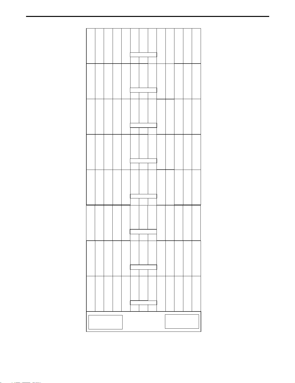
2-3
Figure 2-1 2-SHELF 3000 SERIES SWITCH
Figure 2-2 4-SHELF 3000 SERIES SWITCH
P
T
M
P
T
M
01234567891011
16 17 18 19 20 21 22 23 24 25 26 27
SHELF 1
SHELF 2
M
C
IM
C
IM
C
IM
C
IM
C
CM
C
CM
D
CM
D
CM
L
EM
L
E
t
N
eM
V
TM
V
T
12M
S
NM
S
NM
I
TM
I
TM
I
TM
I
T
M
A
W
M
A
W
POWER SUPPLY
N
I
M
t
N
e
N
I
M
M
I
DM
I
D
P
T
M
P
T
M
P
T
M
01234567891011
16 17 18 19 20 21 22 23 24 25 26 27
48 49 50 51 52 53 54 55 56 57 58 59
SHELF 1
SHELF 2
SHELF 4
M
D
CM
D
C
M
C
IM
C
IM
C
IM
C
IM
C
IM
C
IM
C
IM
C
IM
C
IM
C
I
t
N
eM
V
TM
V
T
12M
S
NM
S
NM
I
TM
I
TM
I
TM
I
T
M
C
C
M
C
C
POWER SUPPLY
“A” “B”
N
I
M
t
N
e
N
I
M
M
L
EM
L
E
M
W
AM
W
AM
W
AM
W
AM
W
AM
W
A
M
I
DM
I
D
P
T
M
32 33 34 35 36 37 38 39 40 41 42 43
SHELF 3

3000 SERIES SWITCH
2-4
Figure 2-3 6-SHELF SWITCH RACK LAYOUT
P
T
M
P
T
M
P
T
M
P
T
M
P
T
M
P
T
M
01234567891011
16 17 18 19 20 21 22 23 24 25 26 27
32 33 34 35 36 37 38 39 40 41 42 43
48 49 50 51 52 53 54 55 56 57 58 59
64 65 66 67 68 69 70 71
SHELF 6
SHELF 1
SHELF 2
SHELF 3
SHELF 4
SHELF 5
M
D
CM
D
C
M
C
IM
C
IM
C
IM
C
IM
C
IM
C
IM
C
IM
C
IM
C
IM
C
I
t
N
eM
V
TM
V
T
12
M
S
NM
S
NM
I
T
M
I
T
M
I
T
M
I
T
M
C
C
M
C
C
POWER SUPPLY
“A” “B”
72 73 74 75
80 81 82 83 84 85 86 87 88 89 90 91
N
I
M
t
N
e
N
I
M
M
L
EM
L
E
M
W
AM
W
AM
W
AM
W
AM
W
AM
W
A
M
I
D
M
I
D
3000 SERIES SWITCH
2-5
Figure 2-4 8-SHELF SWITCH RACK SETUP
P
T
M
P
T
M
P
T
M
P
T
M
P
T
M
P
T
M
01234567891011
16 17 18 19 20 21 22 23 24 25 26 27
48 49 50 51 52 53 54 55 56 57 58 59
64 65 66 67 68 69 70 71 72 73 74 75
SHELF 7
SHELF 1
SHELF 2
SHELF 4
SHELF 5
SHELF 6
M
D
CM
D
C
M
C
IM
C
IM
C
IM
C
IM
C
IM
C
IM
C
IM
C
IM
C
IM
C
I
t
N
eM
V
TM
V
T
12
M
S
NM
S
NM
I
T
M
I
T
M
I
T
M
I
T
M
C
C
M
C
C
POWER SUPPLY
“A” “B”
80 81 82 83 84 85 86 87 88 89 90 91
N
I
M
t
N
e
N
I
M
M
L
EM
L
E
M
W
AM
W
AM
W
AM
W
AM
W
AM
W
A
M
I
D
M
I
D
P
T
M
32 33 34 35 36 37 38 39 40 41 42 43
SHELF 3
96 97 98 99 100 101 102 103 104 105 106 107
P
T
M
SHELF 8
112 113 114 115 116 117 118 119 120 121 122 123
M
C
P
M
M
CM
C
P
12

3000 SERIES SWITCH
2-6
This page intentionally left blank.
This manual suits for next models
1
Table of contents


