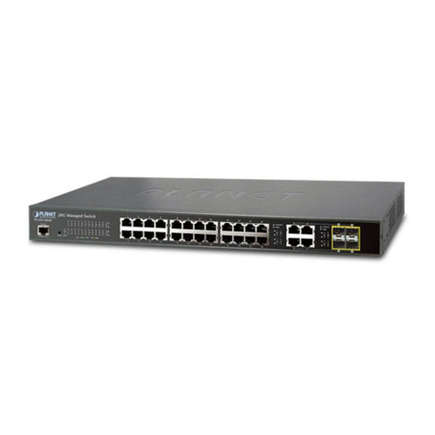
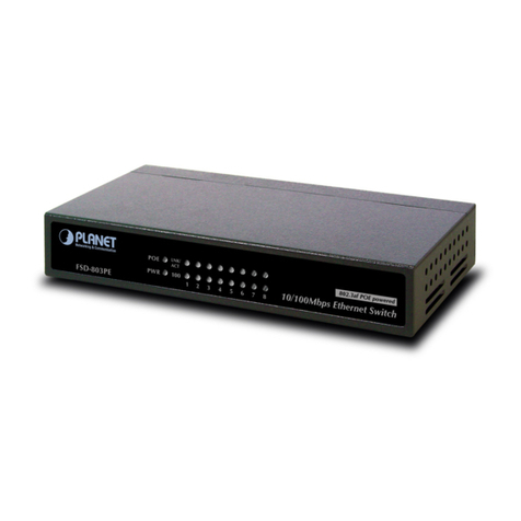
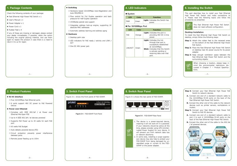
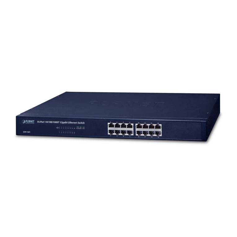
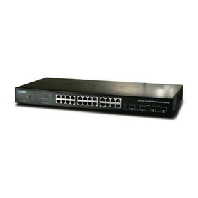
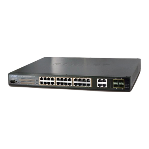
Planet WGSW-2403 User manual

24-port + 3-slot Stackable Ethernet Switch
WGSW-2403
User s Manual

Trademarks
Copyright PLANET Technology Corp. 2003.
Contents subject to revision without prior notice.
PLANET is aregistered trademark ofPLANET Technology Corp. All other trademarks belong
to their respective owners.
Disclaimer
PLANET Technology does notwarrant that the hardware will work properly in all environments
and applications,and makes no warranty and representation, either implied orexpressed,with
respect to the quality, performance, merchantability, or fitness for a particular purpose.
PLANET has made every effort to ensurethat this User sManual is accurate; PLANET
disclaims liability for any inaccuracies or omissions thatmay have occurred.
Information in this User sManual is subject to change without notice and does not represent a
commitment on the part of PLANET. PLANETassumes no responsibility for any inaccuracies
thatmaybe contained in this User s Manual.PLANET makes no commitmentto update or keep
current the information in this User sManual,and reserves the rightto make improvementsto
this User sManual and/or to the productsdescribed in this User sManual, at any time without
notice.
If you find information in this manual that is incorrect, misleading, or incomplete, wewould
appreciate your comments and suggestions.
FCC Warning
This equipment has been tested and found to comply with the limits for a Class A digital device,
pursuantto Part15 ofthe FCC Rules. These limitsare designed to provide reasonable
protection against harmful interference when the equipment is operated in acommercial
environment.This equipment generates, uses, and can radiate radio frequency energy and, if
not installed and used in accordance with the Instruction manual,may cause harmful
interference to radio communications. Operation of this equipment in aresidential area is likely
to cause harmful interference in which case the user will be required tocorrect the interference
at his own expense.
CE Mark Warning
This is aClass Aproduct. In adomestic environment, this product may cause radio interference,
in which case the user may be required to take adequate measures.
Revision
PLANET24-port + 3-slot Stackable Ethernet Switch User's Manual
FOR MODELS: WGSW-2403
Part No.: EM-WGSW2403

TABLE OF CONTENTS
CHAPTER 1 INTRODUCTION..................................................................................................1
1.1 CHECKLIST.........................................................................................................................1
1.2 ABOUT THE SWITCH............................................................................................................1
1.3 FEATURES..........................................................................................................................1
1.4 SPECIFICATIONS.................................................................................................................2
CHAPTER 2 HARDWAREINSTALLATION.............................................................................4
2.1 FRONT PANEL.....................................................................................................................4
2.2 REAR PANEL ......................................................................................................................7
2.3 HARDWARE INSTALLATION...................................................................................................8
2.4 STACK INSTALLATION........................................................................................................10
CHAPTER 3 CONSOLEAND TELNETMANAGEMENT.......................................................11
3.1 CONNECT TO PC BY RS-232 SERIAL CABLE......................................................................11
3.2 TELNET ............................................................................................................................11
3.3 MAIN MENU......................................................................................................................12
CHAPTER 4 WEB MANAGEMENT........................................................................................15
4.1 START AWEB BROWSER SESSION....................................................................................15
4.2 STACK MAIN PAGE............................................................................................................16
4.3 SWITCH MAIN PAGE..........................................................................................................17
4.4 DEVICE CONFIGURATION...................................................................................................20
4.5 TOPOLOGY INFO...............................................................................................................21
4.6 PORTS .............................................................................................................................21
4.7 SECURITY.........................................................................................................................25
4.8 SNMP.............................................................................................................................25
4.9 VLAN..............................................................................................................................27
4.10 IGMP SNOOPING ...........................................................................................................30
4.11 PORT AGGREGATION ......................................................................................................30
4.12 STA...............................................................................................................................31
4.13 PRIORITY........................................................................................................................34
4.14 ADDRESS TABLE.............................................................................................................35
4.15 MIRROR .........................................................................................................................36
CHAPTER 5 TROUBESHOOTING.........................................................................................38
APPENDIXA...........................................................................................................................39
A.1 SWITCH‘S RJ-45 PIN ASSIGNMENTS..................................................................................39
A.2 10/100MBPS, 10/100BASE-TX........................................................................................39
A.3 RJ-45 CABLE PIN ASSIGNMENT..........................................................................................40
- 1 -
Chapter 1INTRODUCTION
1.1 Checklist
Check the contents of your package for following parts:
lWGSW-2403.
lCD-ROM.
lQuickInstallation Guide
lPower cord.
l19”rack-mount brackets.
lRS-232 cable.
If anyof these pieces are missing or damaged, pleasecontact your dealer immediately,if
possible, retain the carton includingtheoriginal packing material,andusethemagainst to
repackthe product in case there is a needto return it to us for repair.
1.2 About the Switch
The WGSW-2403 comes with2410/100Base-TXauto-MDI/MDI-X ports, two slots for
optionalof1000Base-SX, 1000Base-LX, 10/100/1000Base-Tmodules and ashared slot
for a100Base-FX module. Each unithas abuilt-inmanagement interface for configuring
and monitoring through console port, telnet, web and SNMP.
The WGSW-2403 provides a switch stacking function to manage upto 8 switches using a
single IP address. Through its proprietarymanagement bus using astandardRJ-45
cable,thedistance betweenstacked switches can be up to800m.The management bus
traffic is separated fromthe networkports, ensuring heavy networkloading does notaffect
management tasks. Upto208Ethernetports canbemanagedbyasingle IPaddress.
The WGSW-2403 can alsobestacked withPLANETsWGSW-14020 16G Switch and
VC-1602 VDSL Switch, providing the flexibilityfor various applications.
The IEEE 802.1Q withVLAN tagging feature makelogicallyseparatingnodes easier and
up to 255VLAN group are allowedon theWGSW-2403. Rate control is also supported to
allowbandwidth allocationon aper-port basis. Two priorityqueues ensurecritical
applications get thebandwidth and prioritytheyneed.IGMP snoopingis also provided
to prevent flooding ofIP multicast traffic.
1.3 Features
w Complies withIEEE802.310Base-T,IEEE802.3u100Base-TX, IEEE 802.3z
1000Base-SX/LX, IEEE 802.3ab1000Base-T,IEEE 802.1D spanningTree protocol,
IEEE 802.3x flowcontrol, IEEE 802.1Q VLAN, 802.1ppriorityqueuing
w 24-port 10/100Mbps, two slots for 1000Base-T/SX/LX module and oneshared slotfor
100Base-FX port
w 8.8G switching fabric
w Provides 6kMAC address table and 384K bytes memorybuffer
w Supports switchstackable management function, up to8devices anddistanceupto
800mwith single IP

- 2 -
w Rate control function is provided to restrict each port s bandwidth provisionfrom10%,
20% to100%.
w Support 802.1p QoSwith two priorityqueues
w Support 802.1Q taggedVLAN, up to255 VLAN groups can be configured
w Console, telnet, web andSNMP manageable
w Support IGMP snooping
w Port mirroring for dedicated port monitoring
1.4 Specifications
Product 24-port + 3-slot Stackable Ethernet Switch
Model WGSW-2403
NetworkPorts 24 x RJ-45
StackPorts 2 x RJ-45
Module slot 2 for 10/100/1000Base-T, 1000Base-SX and 1000Base-LX
modules
1 for 100Base-FX modules, shared with port 1
Console 1 x RS-232 DB-9
StackID selection Knobwith 8settings (0~7)
Transmission method
Store-and-forward
Switching Fabric 8.8G
MAC address table
size 6k
Packet Buffer Memory
384K Bytes
LEDs System: PWR, Master, Status
Per port: Speed/LNK/ACT, FDX/COL
Port Module:LNK/ACT
Stack: LNK
Cables 10Base-T:2-pair UTP Cat. 3,4,5 up to 100m
100Base-TX: 2-pair UTP Cat.5, up to 100m
1000Base-T: 4-pair UTP Cat 5, up to 100m
1000Base-SX: 50/125and62.5/125fiber-optic cable, up to
550m
1000Base-LX: 9/125 fiber optic cable, up to 10km
50/125 and62.5/125fiber-optic cable, up to
550m
RackMount 19”rackmount, 1U height
Dimension 440 x 285 x 44 mm
Weight 3.6kg
Operating
Environment Temperature: 0~50 degreeC (operating), -20~70degree C
(storage)
Humidity:0~90%,non-condensing
Power Supply 100~240VAC, 50~60Hz, auto-sensing
Power Consumption 40 Watts maximum/ 136 BTU/hr maximum
EMC/EMI FCC, CE
Management
Interface Web, Console, TelnetandSNMP
Protocols and
Standards IEEE 802.3 (Ethernet)
IEEE 802.3u (Fast Ethernet)
IEEE 802.3z/802.3ab (Gigabit Ethernet)
IEEE 802.3x (flow control)
IEEE 802.1D Spanning Tree
IEEE 802.1Q VLAN tag

- 3 -
IEEE 802.1p QoS
RFC 768UDP
RFC 783TFTP
RFC 791IP
RFC 792ICMP
RFC 826ARP
RFC 854Telnet
RFC 2068 HTTP
RFC 2236 IGMPv2
NetworkManagement
RFC 1157SNMPv1/v2
RFC 1123 MIB-2
RFC 1493Bridge MIB
Enterprise private MIB

- 4 -
Chapter 2HARDWARE INSTALLATION
This section describes thehardwarefeatures andinstallation ofthese Switches. For
easier management and control ofthe switch, familiarize yourselfwith itsdisplay
indicators, andports. Front panelillustrations in this chapterdisplaytheunitLED
indicators. Before connecting anynetworkdevice tothe switch, readthis chapter
carefully.
Furthermore, there aresix choices ofdifferent modules for expansion:
l WGSW-D1GT:10/100/1000Base-Tmodule
l WGSW-D1SX:1000Base-SX module
l WGSW-D1LX:1000Base-LX module
l WGSW-D1SC: 100Base-FX module (SCinterface)
l WGSW-D1ST:100Base-FX module (STinterface)
l WGSW-D1S15: 100Base-FX module (SCinterface)
2.1 Front Panel
The unit front panel provides a simple interface monitoring the switch.
100MbpsLNKACT10MbpsLNKACT FDXCOL
PWR LNK/ACT
2526
LNK/
ACT
FDX/
COL
LNK/
ACT
FDX/
COL
MASTER
STATUS
24-port Stackable Ethernet Switch
123456789101112
131415161718192021222324
LNK
INOUT
STACK
Switch ID
RESET
1123456789101112
131415161718192021222324
WGSW-2403 Switch front panel
LED indicators
PWR Green On: Power on
MASTER Green When this LED steady green, it means the device acts
competent leading role (Master), an indispensable essential for
system administrator to control and monitor whole system.
At the time one member ofthe cluster disconnected or new
member joined, the LED blinks. Soon, one and only one master
will be raised. You can refer to “SWITCH ID”section belowfor
relative information.
STATUS Flashing
Green Run Time Erroroccurs
Off No Connection on the port
Green The port is connected at 100Mbps
Flashing
Green There is traffic transverses the port
Amber The port is connected at 10Mbps
10/100
Mbps
ports
LNK/ACT
Flashing
Amber There is traffic transverses the port

- 5 -
Steady
Amber
The port is connected at Full-Duplexmode
Off The port is connected at Half-Duplexmode. Acollision occurs
when two stations within a collision domain attempt to transmit
data at the same time. Intermittent flashing amber of the collision
LED is normal; the contend
ing adapters resolve each collision by
means ofa wait-then-retransmit algorithm. Frequency of
collisions is an indicator of heavy traffic on the network
FDX/COL
Flashing
Amber Collision happens on the port
Green When one slide-in module is well installed and functioning, the
relevant one lights green
Module LNK/ACT
Flashing
Green There is traffic transverses the port
STACK LNK Green On: The switch is stacked to others
Off: The switch is standalone or the stack link have problem
Stack ports
There are twostackports on thefront panel. One is IN andtheother is OUT.When
stacked, the IN port should connect to the other switch sOUTport and the OUTport
should connect toother switch sIN out. You can just use normal Cat 5or better cable with
RJ-45 connector to stack. Onlystraight-through UTP/STPcable can be used.There is no
Duplex Mode issue and themaximumdistance between first and last switchis 800m.
SWITCH ID
Each switch onastack must have auniqueswitch ID.There are eightdegrees (0~7) in
the rotaryswitch. The switch with least switch ID will becomemaster switch and the
others becomeslave. Ifmaster switch is fail or disconnected tothe switch bystack port,
the switch with least switch ID will becomemaster.
Everydevice in the management stackshould have aunique “Switch ID”.In the
meanwhile,a “Switch ID”which has beenusing byadevice, reused byanother, the
management stackwill fail.
Reset button
At the middle offront panel,the reset button is designed for reboot the switch without turn
off and on the power.
10/100MbpsEthernet ports
There are 24 10/100Mbps RJ-45 (copper) ports withone 100Mbps fiber optic slide-in slot.
The slot is shared with port 1 which means ifafiber module is installed in this slot,the first
RJ-45 port will bedisabled.The following pictures showtheavailable module for this
slot.
100Base-FX
WGSW-D1SC
TXRX
100Base-FX SC multi-mode fiber module

- 6 -
100Base-FX
WGSW-D1ST
TXRX
100Base-FX SC multi-mode fiber module
100Base-FX
WGSW-D1S15
TXRX
100Base-FX SC multi-mode fiber module
The auto-negotiationfeature oftheswitch allows each port ofthe devicerunning atone of
the following operation modes:
Port Media Speed Duplex Mode
Full Duplex100Mbps fiber optic (Alternative to
copper port-1) 100Mbps
HalfDuplex
Full Duplex10Mbps
HalfDuplex
Full Duplex
10/100Mbps
10/100Mbps RJ-45 (copper)
100Mbps
HalfDuplex
All copper ports supports MDI/MDI-X automaticallycrossover capabilitythat is the port
can connect either the PC or hub without crossover cable adjustment.
Wiring for 10/100Mbps(Fiber Optic/Copper)
Following are the summaries ofcabling required:
Media Speed Wiring MaximumDistance
10Mbps Category3,4,5 UTP/STP100m10/100Mbps RJ-45
ports 100Mbps
Category5 UTP/STP100m
WGSW-D1SC,
WGSW-D1ST 100Mbps
62.5/125or 50/125µm
multi-mode fiber optic 2km
WGSW-D1S15 100Mbps
9/125µmsingle-mode fiber optic
15km
Ifthe port is connected but the relevantLED is dark, checkthe followingitems:
1. The switch and the connected devices power are on or not.
2. The connecting cable is good and with correct type.
3. The cableis firmlyseated inits connectors intheswitch andintheassociated
device.

- 7 -
4. The connectingdevice,includinganynetworkadapteris well installedand
functioning.
5. Confirmthe connection distance is implemented within the scopeofoperative
without interference.
2.2 Rear Panel
The rear panelofthe switch indicates anAC inlet power socket, which acceptsinput
power from100 to240VAC,50-60Hz, oneRS-232consoleportfor setting up theswitch
via a connectiontoa terminal or PC using aterminal emulation program,and two slide-in
slots for installing additional modules.
2526 CONSOLE
9600, 8, N, 1
100~240VAC
50/60Hz
WGSW-2403 Switch rear panel
Slide-in slots
The twoslide-in slots onthe rear panel are reserved for following optionalgigabit
modules. Theycan provide fat pipes for up linking to backbone or connecting to servers.
1000Base-SX
WGSW-D1SX TXRX
1000BASE-SX : WGSW-D1SX
1000Base-LX
WGSW-D1LX TXRX
1000BASE-LX : WGSW-D1LX
1000Base-T
WGSW-D1GT
1000BASE-T: WGSW-D1GT
The following is thegigabit module operation and cabling required:
Media Speed Duplex Mode
Wiring Distance
10Mbps Full / HalfCategory3,4,5 UTP/STP 100m
100Mbps Full / HalfCategory5 UTP/STP100m
1000BASE-T
1000Mbps Full Category5 UTP/STP100m
62.5/125 µmMMF 220m1000BASE-SX 1000Mbps Full 50/125 µmMMF 500m
62.5/125 µmMMF 550m
50/125 µmMMF 550m
1000BASE-LX 1000Mbps Full
9/125 µmSMF 10km
NOTE: MMF-multimode fiber, SMF –Single mode fiber

- 8 -
Console Port
The RS-232 console is aninterface for connectingaterminal directly.Through the
console port, it provides richdiagnostic information includes network statistics, linkstatus
and systemsetting. The operating mode ofthe console port is:
♦ DCE
♦ 9600(Fix baud rate)
♦ n (No paritychecking)
♦ 8 (8 Data bits)
♦ 1 (1 stop bit)
♦ None (No flowcontrol)
You can use anormal RS-232 cable and connect to the console port onthe device. After
the connection, you can runanyterminal emulation program(Hyper Terminal, Winterm,
Telix, and soon) to enter the startup screen ofthe device.
Power Receptacle
For compatibility with electric service in most areas ofthe world, the switchspowersupply
automaticallyadjusts to linepower in the range100-240 VAC and 50-60Hz.
Plugthefemale endofthepower cordfirmlyinto thereceptacle on therear panelofthe
switch. Plugthe other endof the power cord into an electric service outletthen thepower
will be ready.
Power Notice:
1.The deviceisapower-requireddevice, itmeans, it will not worktill itispowered.If your
networksshould active all the time, pleaseconsider usingUPS (UninterruptedPower
Supply) for your device. It will prevent you fromnetworkdata loss or networkdowntime.
2.In somearea, installingasurge suppression device may also help to protect your switch
frombeing damaged byunregulatedsurge or current tothe Switch orthepower
adapter.
2.3 Hardware Installation
This switchcanbeplaced directlyon your desktop, ormounted in a rack. If youinstall the
device in anormal-standalone standard, theswitch is anmanaged Switch, and users can
immediatelyuse most ofthe features simplybyattaching the cables andturning the
power on. In this case, anymanagerial proceedings areeffective onlyin the rangeofthe
switch. After management stacking, you can enjoythepowerful management functions
and control the whole system.
Desktop Installation
For desktop installation,theswitchneedstoputonaclean,flat deskor tableclose toa
power outlet. Plug in all networkcables and the power cord, then the systemis ready.
Before installing the switch, you must ensure:
1. It is accessible and cables can be connected easily.

- 9 -
2. Cabling is awayfrom:
w Sources ofelectrical noise such as radios, transmitters and broadband amplifiers
w Power lines and fluorescent lightingfixtures.
3. Keepwater or moisture off.
4. Airflow aroundtheunit andthroughthevents in the sideofthe case is great for heat
radiation (companyrecommend that youprovide a minimumof25 mmclearance).
To prolongtheoperationallife of your units:
1. Never stackunit more than eight sets highiffreestanding.
2. Do not place objects on topofanyunit or stack.
3. Do not obstruct anyvents at the sides ofthe case.
Rack-mount Installation
The switch maystandalone, or maybemounted in astandard 19-inch equipment rack.
Rackmountingproduces an orderlyinstallation whenyou haveanumber ofrelated
networkdevices. The switchis suppliedwithrack mounting brackets and screws. These
are used for rackmounting the unit.
RackMounting the Switchin the19-inch rack:
1. Disconnect all cables fromthe switchbefore continuing.
2. Placetheunit the right way up on a hard, flat surface with the front facing toward
you.
3. Locate a mounting bracket over the mounting holes onone side ofthe unit.
4. Insert thescrews and fullytighten witha suitable screwdriver.
5. Repeat the two previous steps for the other side ofthe unit.
6. Insert theunit intothe19" rackand secure with suitable screws (not provided).
7. Reconnect all cables.
Installing Network Cables
StationConnections -
Refer to the wiringstatement ofthe previous section;connect each station withcorrect
type ofcables.
Switch-to-Switch Connections –
In making aswitch-to-switch connection, use Gigabit ports to connect another switch or
backbone isstrongly recommended. The Gigabit ports providethefat pipetotheserver or
backbone connectivityfor boosting thetotal systemperformance. Refer to thewiring
statement ofthe previous section;connect each stationto the switch withcorrect type of
cables.
ModuleInstallation
The two slide-in slots on the rear panel are purposed for installing optional modules. They
can beusedas a networkbackbone or connect toaserver. Follow the steps as described
to install a module:
1. Power off the switch.
2. Removing the two screws on theface plate ofslide-in slot witha flat-head
screwdriver.

- 10 -
3. Push the modulegentlyinto theslot along the slide tracks.
4. Ensuring that it firmlyengages with the connector then tighten the screws to secure
the module.
CAUTION: The slide-inslots are nothot swappable, power off the switchbefore installing
modules.
2.4 Stack Installation
There are two RJ-45 ports on the front panel for proprietarymanagement stack.Only
straight-through UTP/STPcable can be used.
Plugone end ofthe cablein the “IN”port andtheother endto the ”OUT”port ofnext
device. Repeat the step for everydevice in the stackcluster, then ending at last switch.
NOTE:Before management stacking, be sureofeverydevice uses aunique “SWITCH
ID”,or the management stackwill not work.The switch withleast SWITCH ID
will becomeMaster.OnlyMasterswitch smanagement interface (console,
telnet, web and SNMP) is accessible.
Please find thefollowingpicture for sample connection. Please notethe stack port is for
management only.For data packets to be transmitted between switches, youwill still
needto connect their networkports.

- 11 -
Chapter 3CONSOLE AND TELNETMANAGEMENT
3.1 Connect To PC by RS-232 serial Cable
NOTE: Ifyou have stackedseveralswitches together, makesure you are working on
Master switch (switchwithleast SwitchID). Other slave switches management
interface allows onlyviewing theconfiguration by “guest”account.
Toconfigure the system,connect the provided serial cable toaCOM port on aPC or
notebookcomputer and toserial (console) port ofthe device. The console port ofthe
device is DCEalready,sothatyoucanconnect theconsole port directlythrough PC
without the need ofNull Modem.
Aterminal programis required to makethe softwareconnectionto thedevice.Windows'
Hyper Terminal programmaybeagood choice. It canbe accessed from the Startmenu.
ClickSTART, then Programs, Accessories and then Hyper Terminal.
MS-DOS basedterminal programsuch as PC-PLUS,PROCOMM,canalso makethe
connection withthedevice built-in software. The COM port should be configured as:
♦Baud : 9600
♦Parity: None
♦Data bits: 8
♦Stop bits: 1
♦FlowControl : None
Ifyouare usingWindows95/NT/98/2000/XP,launch “HyperTerminal”,createanew
connection, andadjust settings as below:
Please then power on theswitch; launch thenewterminal program you just set up.Press
“Enter”key,thenlogin screen appears. Please check chapter 3.3 for detail on console
management.
3.2 Telnet
To access the switchthrough a Telnet session:
1. Be Sure ofthe switch is configured with an IPaddressand theswitch is reachable
froma PC.

- 12 -
2. Start the Telnet programon a PCand connect to theswitch.
The management interface is exactlythe same with RS-232 console management except
the “root”privilege is not supported.
3.3 MainMenu
After you enter the switch sconsole interface byRS-232 cable or telnet, thefollowing
pageis shown. Please enter username and password to access WGSW-2403.
There are threesystemdefaultaccounts for different privilege levels:
“root”:root candoanyconfiguration includes changingpassword and enable/disable
management capabilityvia console port. The default password ofroot is
“superuser”.Notethat this account is notworkable ontelnetandweb
management interface.
“admin”admin candoanyconfigurationexceptchangingpassword. Thedefault
password ofadmin is “admin”.
“guest”:guest can viewthe whole switchinformation only,moreover, access to Web
management interface is not allowed.The default password is “guest”.
Main menu appears after successfullyloginWGSW-2403.To enter anyofthe submenus,
simplytypethe number after the command prompt. When select further options, you
maybe asked for the device ID which you want toconfigure. Please just input the
SWITCH ID which you have configured on the switch front panel.
The followingtable showsall theavailable optionson theswitch. The management
functions areexactlythe samewithweb-basedmanagement interface but in textmode.
For further operation, please refer to Chapter 4, “Web Management”.

- 13 -
Main menu Submenu Function
1. TopologyInformation
ShowtheDevice ID, Hardware version,
Boot-up version, POSTversion, runtime
code version, agent status, device name
anddevicelocationofeach switchonthe
stack.
2. SystemInformation
Showdetail systeminformation ofeach
switch includingtheir hardware, software
version, systemup time, systemcontact,
device name, device location and system
management capabilities.
1. System
Information
3. SystemConfiguration
Modifysystemcontact, device nameand
devicelocationofeachswitch onthe
stack.
1. Network
Configuration Configure each switch sIP address,
subnet maskand default gateway.
2. ConsolePort Status
Display Displaythe console port configuration, like
baudrate, databits, parity,etc.
3. SNMP Community
Setup
Create, modifyor deleteSNMP
communityname, theIP address
associated with the nameand theaccess
right. Up to 5 entries are supported.
4. Trap Receiver Control
Create, modifyor delete the community
name, IP address and aging timeofthe
trap receivers. Upto 5receivers are
supported.
5. Management
Features Control
Enable ordisable web,telnet andSNMP
management function oftheswitch.You
can also change the http port number on
this menu.
2. Management
Setup
6. Trap Filtering Setup Define which events will trigger the trap on
this menu.
1. Port Status /
Configuration
Showthe status ofeach ports and
configure eachports settings.Italso
allowsyouto configure eachport sspeed,
duplex, flowcontrol and bandwidth
allocation..
2. Address Table
Create, delete and displaythe MAC
address entries ofeachport. You can
also modifytheagingtimeand search a
specified MAC address on this menu.
3. VLAN
TwoVLAN modes aresupportedonthis
switch, 802.1Q VLAN and port group
VLAN. Please select theVLAN mode
first and then makefurther configuration.
Please refer tosection4.9 for detail
configuration available on this switch.
4. SecurityThis function is reserved for future use.
3. DeviceControl
5. IGMP Snooping Enable ordisable the IGMP Sn
ooping.
You can also displaytheIPmulticast
registration table on this menu.

- 14 -
6. Mirror Enable or disable themirror function and
choose thesniffer port and monitored port.
7. Statistic Information Show traffic information of each ports.
8. PriorityTag Define the 802.1p tagmapping andthe
servicerule. Please refer to section4.13
for detail.
9. STA Show thespanning tree algorithmstatus
and configure its parameters.
10. Port Aggregation Enable or disable the port aggregation
(port trunking) function on specified ports.
4. User
Authentication
This menu allowsyou to configure the
password of root, admin and guest
account. Only root account has the right
to enter this menu.
1. SystemRestart Restart theswitch. Two options are
available: cold startandwarmstart.
2. Default FactoryReset
Reset theswitch backto factorydefault
settings.
3. Timeout Interval
Setup Configurethetelnettimeout interval.
4. TFTP DownloadUpdate the firmware through TFTP server.
5. Local Transfer Transfer the firmware frommaster switch
to slave switch.
6. Ping Ping a IP to test theconnectionstatus.
5. SystemUtility
7. Search Location by
Port Name
Inputaport nameto get the
correspondence ofDevice IDandPort
number.
6. Save Runtime
Configuration Save the configurationyouhave makeon
the switch.

- 15 -
CHAPTER 4WEB MANAGEMENT
4.1 Start AWeb Browser Session
The Web Interface ofWGSW-2403 is codedbyJava Applet and running on the JavaTM
Virtual Machine(JVM) version 1.3.1 platform. You should configure the management
stationwith an IP address and subnetmaskcompatible withWGSW-2403 for accessing
it. Also, the management station shouldbe well configured and connected toInternet for
automaticallydownloading(upgrading) the suitable JVM through Internet from
http://java.sun.com. Or you can download from
http://java.sun.com/j2se/1.3/download.html and manuallyinstall it.
Note: Usuallythenewer JavaTM Virtual Machineis notbackward compatible.JVM version
1.3.1is stronglyrecommended to ensure properlyoperation.
The default networkconfigurations are as follows:
IP: 192.168.0.1
Subnet Mask:255.255.255.0
Default Gateway:192.168.0.254
1. Activatea web browser and enter theIP address youhave configured in the address
field. A screen pops up andasksfor username/password. Use systemdefault users
name “admin”and password “admin”(If you have configured a newpassword, input
the newpassword) to access WGSW-2403.
2. After Login, the web management will start todownload thejavafile for the switch.
3. After the file download is completed, the following message is shown. Pleaseclick
“Continue”to enter the stack main page.

- 16 -
4.2 Stack Main Page
The stackmain page contains two options:
Topology
This screen displays one or more switches ofthemanagement stack. Basic properties
can be read bythescreen, including Hardwarecharacteristic, Device Name, Up time,
Master and Slave relationship.Also, bymouse clicking listed items can enter for further
operation.
System Configuration
IfyouaremanagingaMaster or aStandalone device, the systemconfiguration
parameters are equal to parameters ofNet Configurationand Device Informationin
Device tab. For further information, please refer to Device statement.

- 17 -
4.3 Switch MainPage
SwitchMain Page appears after you clickone oftheswitch(es) on the topologypage.
There are 8 function button listed on top: Home, Save, Default,Reboot,Ping, Telnet,
Contact,and Upgrade.
<Home>
Shortcutto backto stackhome page
<Save>
Save the currentsettingto Non-volatile Memory.The difference between <Save> and
<Apply> is that Apply applies settings right awaybutsaves the values in thesystem
memory.Everytimewhenswitch reboots, systemobtains systemparameters from
Non-volatile Memory you <Saved> before butnotsystemmemory.
Select the one(s) you wantto save parameters, then click “Save”button tosave it to
Non-volatile Memory.
<Default>
Makethe switch(es) returning tofactory default value.Select theswitch andclick “Default”
button, theselected-switch(es) will returntoinitial value. Ifyou wanttoclear the previous
value in the System Memory, please <Save> it.
Table of contents
Other Planet Switch manuals

Planet
Planet GSD-802S User manual

Planet
Planet WGSW-20160HP User manual

Planet
Planet WSW-2401A User manual

Planet
Planet GSD-1020 User manual

Planet
Planet GS-4210-8UP2S User manual

Planet
Planet FNSW-1601 User manual

Planet
Planet GSD-800S User manual

Planet
Planet IPOE-270 User manual

Planet
Planet XGS-6311 Series User manual

Planet
Planet VC-412 User manual

Planet
Planet GSD-604HP User manual

Planet
Planet FSD-804P User manual

Planet
Planet POE-1200 User manual

Planet
Planet IGSW-24040T User manual

Planet
Planet GSD-Series User manual

Planet
Planet IGS-10020M User manual

Planet
Planet IGS-10020PT User manual

Planet
Planet FGSD-1022 User manual

Planet
Planet ISW-1022M User manual

Planet
Planet SGS-6340-24T4S User manual