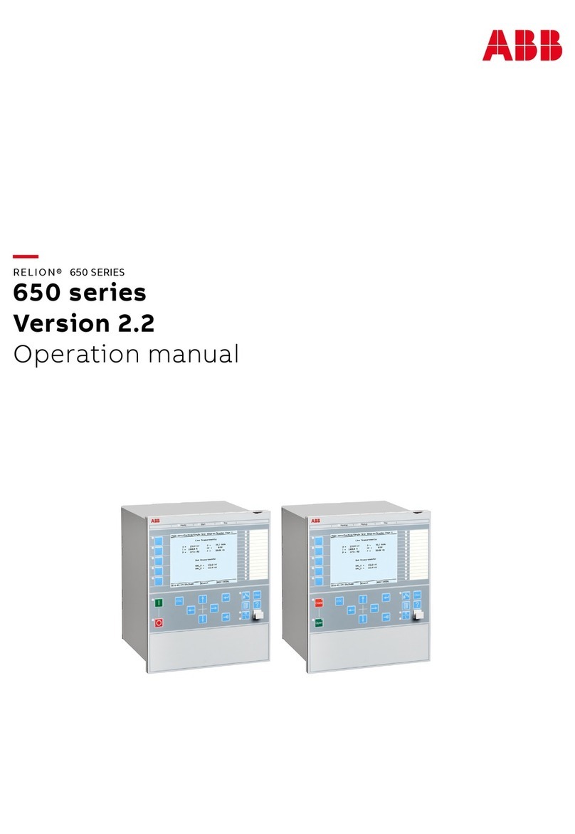
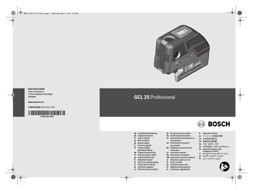
E-one VC3268C+ User manual

Super integration
Professional clamp meter
Instructions of our product
vc3268C+
True RMS AC clamp multimeter
vc3268D+
Real effective value of AC and DC Clamp Meter
VC3268P
True RMS AC clamp power meter

Limited waranty and limited liability
We ensure that no material and technical flaws of E-ONE products from the date of
purchase within one year. This warranty does not include the fuse, disposable batteries
or the products damaged due to accident, negligence, misuse or nonhormal
conditions ofuse orprocessing. Our E-ONE did not authorize dealers to extend the period
of guarantee. Ifrepairing needed during the guarantee period, please sent the test
instrument attached with fault description to distributors or sent directly to the factory.
This warranty is your only compensation. Apart from it, E-ONE makes no expressed or
implied wa:ranty (for example ensure the adaptability of a special purpose). At the same
time, E-ONE shall not be responsible for any special, indirect, incidental consequential
damages or losses resulting from any causes or guesses.
Because of some countries or regions does not allow to limit thc impliod
warranties and the attached or following damages, the scopo of
responsibility and regulations may have nothing to do with you.
Catalog
I. Thebrief introductions.......... "....'.................. I
III. The general instructions of the instrumeut ....................'.......4
l, The press keys and temrinal ....."..'.'....:.'.....................'.4
2, The display screen.......... ......'...........'....4
IV. Measuring methods .......:............... .'...............5
l, Measurementof DC andAC voltage, line judge'.........'.....................'...5
2, Measurement of AC and DC current ..'...'..'.....'.............'.7
3, Measuring the resistance and continuity testrng ...'-..........'..'......'.....:....9
4, Testing capacitance ...'...'..10
5, Measuring frequency and phase discrimination ......'.... 11
rture............... .'.....'...13
7, Measuring single-phase electric power parameter (only P type) -....'...14
8, Data retention / peak holding/ minimum holding / relative value'........19
V. The product specifications .......'..'.......'......... 21
l, General specifications .........'...'......."..'-..............'.'.... 21
2, Technical specifications -.....-:-.................23
Vl. The maintenance -.--.-.............26
VII. After sale services .................27

I . Introductions
&.&wa"rrirg
To avoid electric shock or injuries to people, please read the" safety instructions" and the
"w.arnings and precautions "before using.
VC3268 digial clamp multimeter series (hereinafter referred to as "instrument")
Belongs to the largest count instrument which can maximumly show 10,000 count
resolution.
The clamp meter using battery power with digital screen.
Unless otherwise stated, the description an dinstructions in this manual applies to
VC3268C+, VC3268D+ andVC3268P three types of insffuments.
Unless otherwise marking, all the sketch maps are for VC3268C+ type instrument.
II. The safety instructions
VC3268 digital clamp multimeter series are designed in accordance with
IEC 1010-l CAT I 1000V, CAT II 600V, CAT m 300V voltage standards.
They must be used in accordance with the provisions of the instuotions, otherwise the
protection provided by the instrument may be invalid.
The "warning" shows the states and actions that may cause hann to the users.
The "Notice" shows the states and actions that could cause damages to the instrumont or
the measuring device.
Please use the instrument referring to the safe work habits.
I
&& warning and notes
In order to avoid electric shock, personal rnjury and damage to the meter or to-be-tested
equipment, please use the meter based on safe working habits.
=>Please check the case before using the meter. Do not use the meter with a damaged case.
Check whether there is any crack or missing plastic parts. Please pay special attention to the
insulation layer ofthe contact.
=>Please check and test whether there is any damaged or exposed metal on the wire
insulation. Test the wire continuity. If a wire is broken, please use the meter after replacing the
broken wire.
:>Measure the known voltage with the meter and make sure the meter works normally. Please
do not use the meter which works abnormally as the protective facility may be broken. If there
is any problem, please have the meter repaired.
:>The voltage between any terminal and ground wire shall never be larger than the rated
voltage.
=>Please be very careful when the operating voltage of the meter is larger than 25V, the mean
AC voltage, 42Y, the peak AC voltage or 36V, the DC voltage, as the electric shock risk
exists under these circumstances.
=>Use the correct terminal, function and range scale in measurement.
=>Do not use this meter around the explosive gas, steam or dust.
:>In the process oftesting the probe, fingers shall keep behind the protective device.
=>In the process of testing the wire connection, please connect the meter terminal fust, then
connect the charged to-be-tested terminal and disconnect the test end at last.
:>Before testing the resistance, continuity, diode or capacitance, the power must be cut offfrst
and all high-voltage capacitors must be discharged'

€ffis
&& Warning and notes (continued)
=>The safety function of the meter may be invalid if the meter is not used according to the
instuctions.
:>For all DC functions, including the manual and automatic scales, please use the AC
function first to make sure there is no AC voltage and to avoid the electric shock hazard
caused by the possible wrong readings. Then select a voltage range which is greater
than or equal to the AC voltage range.
=>Please do not use the meter when its case (the entire case or part of the case) is taken
off.
:>This meter shall use three AAA batteries which are installed in the battery compartment
correctly.
=>The battery shall be replaced immediately when the batlery indicator 10; is on. The
meter may display wrong reading and cause electric shock or personal injury when the
power is low. Meanwhile, the battery with low power is likely to incur leakage and
. cause meter corrosion.
=>The test wire must be removed from the meter before the case or the battery cover is
opened.
=)Do not measure the voltage which is above 600V for the II category and do not measure
the voltage which is above 300V for the trI category.
=>If the symbol 1'; sho*, at the REL mode, please be very careful as there might be
dangerous voltage.
=>The replacement parts used for repairing the meter must be the ones specified by the
factory.
=>In order to guarantee the measuremenl accuracy, please do not a just or change the
intemal wiring. This meter has the panel calibration function. If the calibration interface
is entered by mistake (when LCD shows CALI), please shut down the meter
immediately to exit and to avoid the meter data is calibrated wrongly.
3
III. Meter introduction
1. Keys and terminals
Mark number Description
ICurrent test clamp
2Power button, holding key
J Range selection rotary switch
4 Function shift key, relative value
5It is applicable to all testing negative (retum)
input terminals
6It is applicabli to all testing positive inpul
terminals
2. Display screen #ffiffij
Symbol Description
*t&I The panel calibration program is
entered
fi& AC or DC current is selected
uLow battery indication FF Power factor measurement is
selected
rk*r
116
Temperature measurement is
selected ffitr Active power measurement is
selected
wVoltage measurement is selected oPhase measurement is selected
*Current measurement is selected &Relative value is enabled
pF Capacitance measurement is
selected ffi Data hold is enabled
&Resistance measurement is selected NH Peak hold is enabled
ffik Frequency measurement is selected s,m Minimum value hold is enabled

IV. Measuring method
Start-up: Touch the ( C)) tey softly; after hearing the 'obeep" sound and LCD entering the
full display state for one time, the meter enters the measurement state; if the
symbol f,f sno*. display screen, the measurement value may be inaccurate. In this
case, please replace with batteries meeting requirements immediately before
starting measurement. The low battery may cause system crash or start-up failure.
Power-off: Press and hold the ( C)) tey for 5 seconds. After hearing the "beep" sound
constantly, stop pressing the key and the meter shuts down. If the key and range
scale have not worked for 10 minutes continuously, the meter will shut down
automatically. The meter can start up by pressing the ( &) key again.
Note: In order to cancel the automatic power-off insfiuction compulsorily, make the range
locate at the capacitance scale first, then start up the meter.
1. DC and AC voltage measuremeot, live wire distinguishing
l-1. Tum the switch and select a proper range according to the tested AC or DC current.
1-2. lnsert the red probe into VIIzCxQC temrinals and insert the black probe into the COM
terminal.
l-3. Make the probe contact the to-be-tested circuit testi point and measure the voltage.
l-4. Read the voltage value which is measured and displayed on the screen. If the reading is
"0L", it means the measured voltage is out of the current range.
l-5. In the process of measuring DC voltage, if LCD shows the "-" symbol, it means the
terminal connecting with the red probe is the negative voltage temrinal.
1-6. When the voltage to be measured is greater than DC36V (AC25V), the meter will make
abnningsound to remind the user of being aware of high voltage.
l-7. In the process of distinguishing the live wire, turn the rotary switch to the range of
750V. Hold the black probe tightly after winding the wire for many times, then make the
red probe contact with the to-be-measured power socket. If the meter makes sounds for
three times continuously, it means the terminal connecting with the red probe is the live
wire; otherwise, the terminal is the null wire or ground wire.
5
&ro,".
l. When the meter is operated in a dry environment or with gloves, the wire of black probe shall
be winded for more times to increase the inducton intensity.
2. Before using the live wire distinguishing, please meas-ure the AC voltage first and make sure
there is no open circuit in the tested circuit to avoid wrong distinguishing due to over-high
induction voltage ofthe circuit.
DC voltage measurement diagram
AC voltage measurement diagram

E
2. DC IAC current measurement
/rft.
;ffi, Notes
l. When the tested current is less than 5% of the measurement range, the measurement
value may be inaccurate. Please select a proper measurement range to lower the
measurement uncertainty.
2. Ifthe meter cannot be calibrated or set back to zero under special circumstances, it shall
be subtracted from the measurement reading.
2-1. Tum the switch and select a proper range scale based on the tested AC or DC current.
2-2. Open the clamp head and get stuck on the measured wire. The measured wire shall be
located at the center indicated by the kiangular symbol of clamp head vertically. Check
whether the clamp head is closed well.
2-3. Read the measured current value on the display screen. If the reading
means the measwed current is out of the current measurement range'
24. lnthe process of measuring DC current, open the clamp head and get stuck on the
. measured wire. The reading displayed on the meter is the initial current. Remove the
clamp head from the measured wire after the reading is stable. If the meter still shows
a non-zero reading, this reading is the remanence of the clamp head and shall be
calibrated to zero by touching the A key lightly. (the following operation methods are
identical to those of VC3268D+)
2-5. After calibrating the remanence reading of the meter to zero, open the clamp head and
get stuck on the measured single wire again. The measured wire shall be located at the
geometric center of clamp head vertically. Check whether the clamp head is closed
well.
2-6. Read the measured current value on the display screen and the LCD reading is the
measured DC current value. The current flows through the measured wire from top to
down. If LCD shows the'1" symbol, it means the current flows through the measured
wire from down to top.
7
The current direction in the process of measuring DC
current (watch out the direction when VC3268D|- is used)
Current measuremeot diagram
What is aTRMS?
TRMS means "true root mean suare" which is abbreviate to "TRMS". In some documents, it is
also called True RMS. RI4S-Make DC current and AC current flow through two identical
resistance devices respectively. If the heat generated by them is equal over the same time frame,
the DC current value shall be regarded as the RMS of the AC current. The RMS of a sinusoidal
current is 0.707 times of its peak value. The core component of a TRMS meter is TRMS/DC
converter. Due to its high cosq usually it is not adopted by general multi-meter. With the
development of large-scale integrated circuit, it is integrated to a single monolithic chip. The
monolithic integrated circuit has many advantages such as high integration level, full function, a
small quantity of peripheral components, easy circuit connection and high assurance level of
electrical property index, etc. Such kind of chip can measure the RMS of various voltage
waveforms accurately in real time with no need to consider the waveform parameter or
distortion. tn addition, the AC frequency response can reach above lOOkHz. All these
performances cannot be matched by any mean value meter.
is "0L", it

3. Resistance Measurement and Continuity Testing
&& wu*irg
Before continuity testing on resistance or electric circuit, please make sure the power
supply for the electric circuit is cut off and electric discharge of all the high-voltage
capacitors is made in case of electric shock or instrument damage.
3-1. Tum the switch, choose an adequate resistance measurement range profile.
3-2. Insert the insertion ends of red probe and black probe into YHZCXQ"C terminal and
COM terminal respectively.
3-3. Connect the probes to both sides of the resistance to be measured and make sure
reliable connections.
3-4. After the stabilization of reading, read the measured resistance value displayed on the
viewing screen. If the reading is "0L", it indicates the measured resistance exbeeds
the measuring range.
3-5. At the measuring range profile of "ll , continuous sound indicating short circuit will
be emitted from the buzzer if the resistance of the measured circuit does not exceed
30O. If the reading of "0L" is displayed on the instrument, it indicates open circuit.
Exclusive Clamp-type Multimeter
4. Capacitance Testing
&* Waming
In capacitance measuring, please make sure the power supply for the electric circuit is cut off
and it is suggested to undertake electric discharge of all the high-voltage capacitors in case of
electric shock or instrument darnage. The instrument damage due to the negligence of elechic
discharge of measured capacitor can be reduced as much as possible through the self-healing
electronic protection function of this instrument. However, the discharge voltage should not be
higher than 250v, arrd accurate capacitance measurement can not be achieved until the thorough
circuit recovery 3 minutes after the protection.
4-1. Turn the switch, choose a capacitance measuring range profile.
4-2. Insert the insertion ends of the red probe and black probe into VHZCXQ'C terminal and
COM terminal respectively. Ifthe probes are in open circuit and return-to-zero can not be
achieved, please press key A to adjust the display to zero.
4-3. Connect the pins ofthe probes to both sides ofthe capacitors to be measured respectively,
make sure the contacts are reliable.
44. After the stabilization of reading, read the measured capacitance value displayed on the
viewing screen. If the reading is"0l", it indicates the capacitance of the measured capacitor
exceeds the measuring range.
Graphic Representation Involving Resistance Measwement and Continuity Testing Graphic Representation Involving Capacitance Measurement

( ^Eranrralsy Measurement and Phase Sequence Judgement
Al\ wamings
1. If the amplitude voltage of a frequency to be measured is lower than 25Y the
measurement might be inaccurate and the result is only for reference. The voltage limit
for a frequency measurement is 250V (mean effective value), measurement of a
voltage higher than the limit value is not allowed in case of eleckic shock or
instrument damage.
2. tn phase sequence judgement, to guarantee accurate judgement, before testing, please
make clear whether there is phase loss in the system that should have three phases by
making use of the live wires and make sure there is no phase loss.
5-1. Turn the switch to choose a frequency measuring range profile, then "kHz" should be
displayed.
5-2. Insert the insertion ends of the red probe and black probe into the VHZCXO'C
terminal and the COM terminal respctively.
5-3. Connect the pins of the probes to the two ends of the circuit to be measured, make
sure the contacts are reliable.
5-4. After the stabilization of reading, read the measured frequency value displayed on the
viewing screen. If the reading is"0l", it indicates the frequency measured exceeds the
measuring range.
5-5. To make a phase sequence jud8emenffiase press key t( ) to enter into the mode
of phase sequence judgement, then UUU will be displayed on the display screen,
insert the insertion ends of the phase sequence accessories into the COM and
VHZCXQ"C terminals of the instrument respectively.
5-6. Connect the yellodblack/red line clamp to the three testing endpoints, i.e., phase a,
nhacc ! and phase c, of the three-phase power source respectivejly. the display of
nrr - --- nn
nEL indicates positive phase sequence. The display of liU indicates the
existence of anti-phase or phase loss, in this case, please make the red lir^*;{rmn and
black line clamp replace each other and phase loss is indicat.6 6 *lU is still
displaced.
11
Graphic Representation Involving Connection Graph Involving Phase
Frequency Measurement Sequence Judgement
Typical Application in Phase Sequence Judgement?
The phase sequence refers to the three-phase sequence ananged in accordance with phase
angle sequence, positive phase sequence refers to the three-phase sequence l6anged in
cloclavise direction as shown in the picture below, reverse phase sequence refers to the
sequence arranged in the anticlockwise direction. Before the availability of a
phase-sequence meter, the electrician usually undertakes wire connection for a
tlree-phase motor andjudges the phase sequence via the rotation direction ofthe motor,
the motor rotation in positive direction indicates positive phase sequence, and the reversed
rotation ofmotor indicates reverse phase sequence. However, the absolute phase sequence
wiring of a three-phase power supply from power plant can not be distinguished through a
common phase-sequence judgement by a phase-sequence meter.
l* lB tG
reotr'J\rm' reofrf\rrc lerya*=\to"
_4*_ ^4r*- **#{-
Positive Phase Sequence I Positive phase sequence 2 Positive Phase Sequence 3
t2
lffi,i

6. Temperature Measurement
AA wamings
l. Getting the temperature probe in touch with a high-voltage object for the purpose of
measurement is prohibited in case of electric shock or inskument damage.
2. Please take notice that the temperature measurement probe should be accompanied
with a meter during application, Wff should undertake calibration before temperature
measurement probe replacement.
6-1. Tum the switch, choose a temperature measuring range profile (connection with a
matching temperature measurement probe is a must).
6-2. Insert the corresponding plugs of the semiconductor temperature measuring probe
into the COM terminal and VIZCXQ'C terminal of the meter respectively.
6-3. Hold the hand shank of the temperature measuring probe manually, get the probe in
touch with the object to be measured and make sure reliable contact.
34. After thc stabilization of reading, read the measured temperature value displayed on
the display screen. "0L" indicates the temperature measured exceeds the measuring
range.
3-5. Switchover between Celsius displacement and Fahrenheit displacement can be
achieved by pressing key '( F.
7. Measurement of Single-phase Electric Power Parameter (only for VC3268P model)
A 6urr,ior.
1. If an electric current is smaller than l/10 of the measuring range or exceeds the measuring
range, the measurement might be inaccurate, please choose an adequate measuring range for
measurement in order to reduce the uncertainty degree of measurement. If the elecfric current
exceeds the measuring range or if a 2OA-grade current is smaller than l/10 of the measuring
range, symbol "A" will be displayed on the display screen, reminding the user that the
reading at the time is only for reference.
2. The relevant technical indicators provided by the meter is used for the measurement of
parameter of sine-wave alternating current and might bring about inaccuracy in non-sine wave
measurement.
7-1. Turn the switch, choose an adequate electric current measuring range profile, record the
measured electric curent value and guarantee an adequate measuring range by referring to
the way of electric current measurement.
7-2. Insert the insertion ends of red probe and black probe into the VHZCXQ"C terminal and
COM terminal respectively.
7-3. As shown in the picture, connect the probe(s) and tong head, make sure reliable connections.
7-4. Cyclical selection of the power parameters of kW, PF and phase position is able to be
achieved by pressing key { }
7-5. After stabilization of reading, read the measured value displayed on the display screen. The
displacement of "0L" indicates the measured parameter exceeds the measuring range at the
time.
7-6. Ir power factor measurement, the maintenance of minimum value and measurement of
instant minimum power factor can be achieved by pressing key H. PH for over two
seconds so.as to facilitate analysis and compensation. t4
I
l
x
I
N
t3
Involving Temperature Measurement

Cunent Direction in Power Measurement
Graphic Representation Involving Single-phase power Measurement
Graphic Representation A Involving
Measurement via One Meter
Graphic Representation B
Measurement via One Meter
Involving
ExpandedApplications of VC3268P Clamp-type Power Meter in Three-phase Power Supply
l. In the state of load equilibrium in Three-phase Three-wire system:
Under the circumstance that the loads of the three phases'are the same, the sum of the powers of
the three phases can be worked out with the aid of power measurement of any the of phases in
the three-phase three-wire system with a single-phase digital power meter;
i.e., P6"1: Pl * P2 or P6o61: PlX2 (Pl : P2)
PF : Upper PF value on single-phase power meter. Example: Upper reading on the power
meter: l20kW, sum of the powers of three phases: l20kWX2:240kW.
2. In the case of unbalanced loads in three-phase three-wire system:
2- I . In the case of relative invariability of load to be measured (non real-time power) :
Take one phase as reference pirase c (as indicated in the graphic representation involving
measurement via two meters), clamp the wire of phase a via tong head, make the pins of the red
probe and black probe get in touch with the voltage ends ofphase a and phase c respectively,
record the power reading Pl displayed on LGD.
In the second measurement: Clamp the wire of phase b via tong head, make the pins of the red
probe and black probe get in touch with the voltage ends ofphase b and phase c respectively,
record again the power reading P2 displayed on LCD.
2-2. Real-time Power Measurement or the Measurement of Instant Load Change (real+ime
power):
Measure via two meters. Prepare two digital power meters which are the same. Meter one
should clamp the wire of phase a via tong head, get the pins of its red probe and black probe in
touch with the voltage ends of phaso a and phase c respectively; clamp the wire of phase b with
the tong head of meter two, get the pins of the red probe and black probe of meter two in touch
with the voltage ends of phase b and phase c respectively. Simultaneously watch the power
readings Pl and P2 displayed by the two power meters respectively.
Then the total power at the timo: P64:Pl + P2
Example: The readings of the two measurements are 80kW and l20kW respectively,
Sum of the active powers of the three phases: P.,'1:80kW+ l20kW:200krJV.
t5 l6

Exclusive Clamp-type Multimeter
2-3. If PF:0.58 cun, the reading of one phase in Pl or P2 is zero, and Prol: pl or P2; If
PF<0.5, the reading of one of the phases is minus, and P64:Pl -P2 orP}-Pl.
2-4.Power factor calculation under the circumstance of three-phase dissymme@:
PFtotur: total active power/total apparent power; total appaxent power: (UlXIl) +
(u2xl2).
Example: The measured active powers: 20KW and 30KW
Ul and U2 are all 380V, I I is 60A, I 2 is 80A.
PFrotor: Q0+ 30) l(380X60 + 380X80):0.94.
3. In the state of unbalanced loads in three-phase four-wire system:
3-1. In the case ofrelative invariability ofload:
Get the pins of the red probe and black probe in touch with the voltage end of phase a
and the null line respectively, clamp the wire of phase a with the tong head, record the
power reading Pl displayed by LCD.
In the second measurement, get the pins of the red probe and black probe in touchwith
the voltage end of phase b and the null line respectively, clamp the wire of phase b by
the tong head, record the power reading P2 displayed by LCD.
In the third measurement, get the pins of the red probe and black probe in touch with
the voltage end of phase c and the null line respectively, clarnp the wire of phase c with
the tong head, record the power reading P3 displayed by LCD.
Active power of three-phase four-wire system: P.,.1 :P I + P2 + P3; power factor: PF :
P,o,a /total apparent power.
The active power of each subcircuit can be obtained from the corresponding VG3268P
reading, an apparent power : a distinct voltage reading displayed X the reading of
corresponding current intensity.
\I/iring Diagram Involving Power Measurement of
Three-phase Three-wire Systern via TWo Meters
Wiring Diagram Involving Power Measurement of
Three-phase Four-wire System via Three Meters
t7
18

ffirffi
8. Data hold/peak hold/minimum value hold/relative value
8-1. Data hold: In the measurement range of voltage, curent, frequency, resistance,
temperature, capacitance and power parameter, if it is not available to get the reading,
please hold the measurement result on LCD screen and tough H. PH key lightly. After
hearing a "beep" sound, the LCD screen shows a "H" symbol and CPU holds data on
the display screen automatically. The data hold function can be exited by switching the
range scale or lightly touching H.PH key again.
8-2. Peak hold: In the measurement range ofcurrent and voltage, press the H.PH key for
more than 2 seconds. After hearing a "beep" sound, the meter enters into peak hold
state and LCD screen shows a "PH" symbol. The high-speed A"/D takes samples from
the measured signal at the sampling rate of 4000 times/second and captures the
periodic signals which are greater than 250uS. CPU holds the peak value and shows it
on LCD. This frrnction makes it very easier to measure the impulse current or flicker of
motor or electrical load.
8-3. Minimum value hold: In the measurement range of power factor, the transiently
changed minimum power factor must be measured. In the measurement, press the
H.PH key for more than 2 seconds. After hearing a "beep" sound, the LCD screen
shows a "H" symbol and a A symbol and enters into the minimum value hold state. At
this moment, CPU compares data in the measurement process and only holds the
minimum power factor and displays it on LCD. The refresh rate of minimum value
hold data is 2.5 seconds/time.
8-4. Relative value measurement: In the measurement range of voltage, resistance and
capacitance, the relative value measurement function can help you to calculate the data
of secondary measurement (subtract the measured value before pressing the key from
the measured value after pressing the A key, and the result is the relative value).
Touch the A key lightly. After hearing a "beep" sound, the meter enters into the
relative value measurement state. The relative value measurement function can be
exited by pressing the key again.
t9
What are CAT standards?
CAT standards are safety standards specially made for electronic instruments by the Intemational
Electronic Electrician Standard Committee. The major standard divides overvoltage into four
categories. The higher the category level is, the wider the service environment and range are and
the more difficult the product design and production are. VC3268 series clamp meters are
designed according to CAT-III standards and are safe and reliable.

Function Input terminal Maximum input value
DCV v/o COM IOOOVAC RMS/DC
ACV v/o COM 75OVAC RMS/DC
ov/o COM 25OVAC RMS/DC
Hz v/o COM 25OVAC RMS/DC
Cx v/o COM 25OVAC RMS/DC
cv/C) COM 25OVAC RMS/DC
V. Product specification
l. General specification:
The limit value of input voltage of test terminal (1 minute at most):
Display screen:
Sampling rate:
Battery type:
Total quiescent
current:
Working
environment:
Storage
environment:
Meter size:
Package size:
Total weight:
Accessory list:
Digit, the maximum display value is 9999
4000 times/second
Three AAA l.5V batteries
About20mA
0C-40C; relative humidity: <80%RH
- 10C -+50C ; relative humidity: <85%RH
208X70X33mm; maximum opening of clarnp head: 45mm
242X170 X50 mm
About 5509 (including batteries)
One Operating Instruction (manufacturer certificate), a pair of
testing probe, one semi-conductor temperature measurement
probe, one phase sequence accessory and a pair of testing wire
clamp (for P model only)
What is an all-in-one professional clamp meter?
The clamp meter is a coflrmon instrumental meter which is necessary for power installation and
electro-mechanical equipment maintenance, The function combination of the previous design is
weak and cannot meet the field test demand. Many clamp meters with lower prices are zuitable
for maintaining air conditioner or meeting the general test demands of electrician. Firstly, a
professional clamp meter must meet intemational safety standards and reach the CAT -III level.
The insulation test shall exceed 5500V. Secondly, the meter shall be able to measure the TRMS
and detect the non-sinusoidal wave signal accurately. Thirdly, it must have a very reliable
protection mechanism to prevent the meter from fusing in the test range. Fourthly, the meter must
have a proper detection frrnction combination. VC3268 series completely meet the above
requirements. In addition to test the dernanded current and voltage range, the meter must have the
unique semi-conductor quick temperature measurement function and the power/capacitance
detection function. In addition, the meter must have the power/capacitance self-discharge
protection mechanism. Digital display phase sequence, live wire distinguishing and relative value
measurement make VC3268 series clamp meters be unique all-in-one professional meters.
What is the difference between different models of VC3268 series clamp meter?
YC3268 series clarnp meters include three models which are VC3268C+, VC3268D+ and
VC3268P respectively. All these meters use the dedicated chip for TRMS and 24-bit high-speed
A./D convertor. [n order to realize isolation and antijamming of ulta density components, the
meter is made by a four-layer circuit board.
The test object ofVC3268C+ isAC current.
VC3268D+ added DC measurement with .The basic functions are all the same.
VC3268P is a clamp power meter measuring small power paramet€rs. It is applicable to
energy-effrcient equipment installation, electric balance debugging, electric energy meter wiring
distinguishing and refrigeration equipment maintenance, etc. ,,.|
2t

2. Technical specifications:
The uncertainty is only applicable when the meter needs to be adjusted after it is calibrated
for one year. Please visit WWW, E-ONE. IYET. CN to download the related data.
The environmental condition guaranteeing the uncertainty is 23oC JS"C; the relative
humidity is less than 80%RII; the uncertainty is expressed as *, (reading percentage +
number of significance bit).
2-l.DC/Acvoltage
The input impedance is about 6MQ and the AC frequency response range is from 40IIz to
2kIIz
YC3268C+/P is an AC current measurement; VC3268D+
measurement
AC frequency response: 40Hz-400H2
2-3. Resistance
DC/AC
The test frequenry is about 2. 5Hz and the test voltage is about 5V.
2-7. Frequency
Measurement
range
Uncertainty Resolution Test voltage
2kl{z t ( 1.0olo+5d) lHz >25y
Note: The frequency range does not have the H/?H function; the frequency measurement range is
from 40tlz toZkllz.
2-8. Temperature (semi-conductor probe )
Measurement range Uncertainty Resolution
-l0c -+100c * (2.0o/o+5d) 0.rrc
The open-circuit voltage is about 3.6V.
23
2-4. Continuity test
Measurement
range
Description Test condition
)) <30Q: the buzzer makes a
sound
The open-circuit voltage is about 3.6V
2-5. Capacltatce
Measurement
range
Uncertainty Resolution Model
200 uF * (5.0%o+5d) l00nF C+ID+IP
Measurement
range
Uncertainty Resolution Model
DCV ACV(TRMS)
1000v + ( 1.0%+3d) NO 100mV C+ID+IP
750V NO + (1.2%+3d)
2-6. Phase sequence
Phase sequence Voltage range Display
Paraelectric phase 45V450V ABC
Anti-phase/ default phase 45V-450V NO
2-2.D(JAC current
Measurement
range
Uncertainty Resolution Model
DCA ACA(TRMS)
2A NO *(3.0%+5d) lmA P
30N20A NO +(2.5%+5d) lOmA C+iP
300A/200A + (2.5o/o+5d) 100mA c+D+/P
1000A r(2.5o/o+5d) L(2.5%+5d) IA C+/D+
Measurement range Uncertainty Resolution Model
3kf) + ( 1.0%+3d) lo C+D+/P
3oko + 0.0%+3d) 1ocl C+lP
24

2-g Power measurement ( lor VU326EP
Parameter Measurement ranse Uncertaintv Resolution
Active power 50w-l20kw *(3.0%+5d) l0w
Power factor 0.02-1.00 *(3.0%+5d) 0.01
Phase 0o. 90" r(3.00lo+5d) Io
The minimum input current is lA; the current measurement rezult being less than 1A is for
reference only.
The minimum input voltage is 5V.
Why does a DC clamp meter require zero setting?
VC3268D+ is a AC/DC clamp meter. In order to solve the direct current detection
problem, usually a circuit consisting of Hall elements is used. For each measurement, the
direct current passes through the magnetic circuit consisting of magnetic materials and
Hall elements and the remanence of magnslic materials may influence the next
measurement. In addition, the geomagnetism may have an impact on the test magnetic
circuit. Therefore, a DC clamp meter requires zero setting before the test and VC3268D+
is no exception. The only difference is that VC3268D+ adopts the relative value and
subfacts the remanence reading to guarantee the accuracy of next measurement.
Meanwhile, the current flow direction shall be paid attention to in the measurement.
Why can a semi-conductor measure temperature quickly?
Most common multimeters usually take the k-type thermocouple to work with the cold
junction compensation circuit for the purpose of measuring the temperafure. However, all
coldjunction compensating components require a temperature conduction process which
requires a certain time to balance the measuring circuit; otherwise, the measuring result
will be influenced directly. According to properties of the k-type thermocouple, the output
level is very low in the ambient temperature range and only the internal compensating
diode is in action. Therefore, the test speed is inlluenced aod the measurement error is
larger. The 3268 series clamp meter uses a semi-conductor probe directly and avoids the
utilization of intemal cold junction compensation circuit. In addition, the resolution is
increased to O.lC from lC of a k-type thennocouple. It has one disadvantage which is
the small measurement range; however, the measurement range is still enough for
maintaining refrigeration equipments.
25
VI. Maintenance
l. This insfiument is a precision measuring instument, in order to prolong its service life, please
avoid using in harsh environments.
2. To ensure the measuringt uncertainty, please do not adjust or change the internal circuit.
3. The instument adopts panel calibration, When requiring calibration, please download
the calibration procedures from E-ONE. NET. CN; Notice: do not enter the instrument
panel calibration status without the calibration conditions.
4. If not using for a long time, please take out the battery, to prevent the battery leakage corrodes
the instrument.
5. When replacing batteries, please disconnect the measuring circuit, fasten the screws on
the battery door off, remove the used batteries, and replace new ones.
6. Its surface should be cleaned with Pledge, wiped with dry clothes, and no o ther
chemical agents or sharp objects mustn't be used.
7. If splashed or watered, it can't be used to measure the voltage of more than 20V until the
water dry.
[or
26

VII. After sale services
You have chosen our after-sale services when buying our machine. So what services do
you enjoy?
To make srue you smoothly and correctly use this product, please read the instructions of
the product, If there are still some questions, please send your comments to our company
service center by logining wlil"w. E-ONE.NET.CN, or call our 24 hours service hotline
0756-6698961.
If having been already familiar with the instructions before using the product, you will not
accidently damage the instrument, besides, in circuit design, our VC3268
integratedprofessionalclamp meter series have adopted tle self recoverytype
complete protection measwes, which greatly reduces the damaging probabilities due
to false operating.
After buying the E-One product, please send tle user receipt card ASAP by:
I ) Logining WWW.E -ONE.NE.TCN;
2) Sending text messages to l58l 1668521 (free ofcharge);
3) Faxxing to 0756-8659599;
a) Mailing according to the address;
5) Directly filingl it out and giving it to E-one stores (cabinet).
If any damages happen while using, please send the user forrn along with the
user receipt card to our company repairing service center. We will repair it within ten
days and sendback to you. All the repairing expenses (excluding the costs ofmaterials) are
free within twoyears, to assure you safety both buying and using.
27
E-one oscillograph @be obvious to all
ET521 Bautomatic oscillograph field comprehensive tester
* 200Ms/s sampling rate / dual core technology
* 50MHz digital storage automatic oscillograph
* 60000 u F wide range of capacitance measurement
* l56kHz high frequency inductive automatic range
* loHz-l56kHz function signal output
* 6600 code automatic oscillograph multimeter
* 60MIIZ frequency / duty cycle measurement
* crystal / remote conhol / triode detection
* 200 groups oftest data storage list
* 200 sets ofautomatic recording be convenient to IC detection
* 40 sets ofwaveform storage / call
* fuIl function Chinese help window hints
www.ET52r.NET
This manual suits for next models
2
Table of contents
Other E-one Measuring Instrument manuals

