EA Technology UTL2 User manual

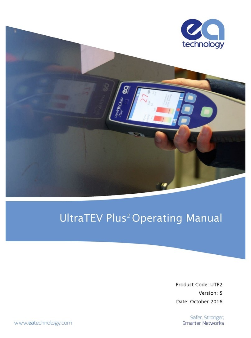
UltraTEV Locator Probe Operating Manual
Model Number: UTL2
Version: V01.03.00
Date: July 2021
EA Technology Limited, Capenhurst Technology Park, Capenhurst, Chester, CH1 6ES, UK
Tel: +44 (0)151 339 4181 http://www.eatechnology.com
Registered in England number 256631

EA Technology UltraTEV Locator Probe Operating Manual 2852-MANUL-V01.03.00

EA Technology UltraTEV Locator Probe Operating Manual 2852-MANUL-V01.03.00
Safety Precautions and Procedures
The UltraTEV Plus² and Locator probe are designed to detect partial discharge sources in High
Voltage (HV) Plant.
If no discharges are detected, this does not necessarily imply that an item of HV Plant is discharge
free. Discharge sites often have dormant periods and insulation structures can fail through causes
other than those attributable to partial discharges.
If discharges of considerable magnitude are detected in plant that is connected directly to the high
voltage power system, the authority responsible for the plant should be notified.
Warnings
•The UltraTEV Plus² and Locator probe are designed for use at ground potential only.
•When testing electrical plant ensure that the metalwork is earthed before applying the
UltraTEV Plus² and Locator probe.
•Maintain safety clearances between structures at high voltage and the instrument and the
operator at all times.
•Adhere strictly to local safety procedures.
•Do not make measurements when there are electrical storms in the vicinity.
•Do not make measurements immediately following the energisation of a circuit.
•Do not disturb plant during measurements either mechanically e.g. by shaking or striking
it, electrically e.g. by increasing the voltage or physically e.g. by applying heat.
•Do not operate the instrument or its accessories in an explosive atmosphere.

EA Technology UltraTEV Locator Probe Operating Manual 2852-MANUL-V01.03.00
Contents
1. General Description ......................................................................................................................................1
1.1 The UltraTEV Locator Probe ....................................................................................... 1
1.2 Non-Intrusive Detection of Partial Discharge Activity ................................................. 2
2. Preparations for use .....................................................................................................................................3
2.1 Connecting the Locator probe to the UltraTEV Plus² .................................................. 3
2.2 Calibrate.................................................................................................................... 4
2.3 Locator probe Function Check ................................................................................... 5
3. Operating Instructions ................................................................................................................................6
3.1 Locator Mode ............................................................................................................ 7
3.2 Locator Advanced Mode .......................................................................................... 10
4. Technical Specification ............................................................................................................................. 13
4.1 General.................................................................................................................... 13
4.2 Environmental ......................................................................................................... 13
4.3 Accessories and Options ......................................................................................... 13
5. Declaration of Conformity ...................................................................................................................... 14
6. Maintenance.................................................................................................................................................. 14
7. Warranty Policy ............................................................................................................................................ 14
8. Calibration ..................................................................................................................................................... 16
9. Repair .............................................................................................................................................................. 16
10. Waste Electrical and Electronic Equipment Directive (WEEE) .................................................... 16
11. Continuous Improvement........................................................................................................................ 16
12. Contact Us...................................................................................................................................................... 17
13. Record of Changes ..................................................................................................................................... 18

EA Technology UltraTEV Locator Probe Operating Manual 2852-MANUL-V01.03.00
Page 1 of 19
1. General Description
1.1 The UltraTEV Locator Probe
The Locator probe is used in conjunction with
the UltraTEV Plus² to further locate TEV
activity, detected during a routine PD survey
of substation assets.
The Locator probe adds a second TEV sensor
to the UltraTEV Plus2. Both TEV sensors listen
for TEV pulses, and when they both detect
pulses they calculate the difference in arrival
time. The standard Locator mode shows
which probe detected the signal first,
indicating the source is closer to that probe.
In some cases of PD, such as when multiple
sources are present, it can be useful to have
more information than which probe is closer
to the source. For such cases the Locator
Advanced Mode provides additional
information in the form of a histogram which
can be used to accurately assess the live data.
This live data can be used to locate multiple
sources at the same time.
The Locator probe is supplied in its own carry
case which can be attached to the top or bottom
of the UltraTEV Plus² carry case, by rotating the
blue T-lock.
TEV Sensor
Magnet
Power Indicator
Down
Up
Level
Cable to UltraTEV Plus²

EA Technology UltraTEV Locator Probe Operating Manual 2852-MANUL-V01.03.00
Page 2 of 19
1.2 Non-Intrusive Detection of Partial Discharge Activity
Partial discharges are electric discharges that do not completely bridge the electrodes. The
magnitude of such discharges is usually small however they do cause progressive deterioration of
insulation that may lead to eventual failure.
Non-intrusive partial discharge detection provides a means for identifying these potential sources
of insulation failure that result not only in loss of supply to customers but can also endanger staff.
A partial discharge emits energy in the following ways:
Electromagnetic:
•Radio
•Light
•Heat
Acoustic:
•Audio
•Ultrasonic
Gases:
•Ozone
•Nitrous oxides
The most practical techniques for non-intrusive testing are based on the detection of the radio
frequency part of the electromagnetic spectrum and ultrasonic emissions. The UltraTEV range has
been specifically developed to enable electromagnetic and ultrasonic activity to be detected in a
single simple to use instrument.
Airborne Ultrasonic Discharge Activity
Acoustic emission from partial discharge activity occurs over the whole acoustic spectra. Audible
detection is possible but depends on the hearing ability of the individual. Using an instrument to
detect the ultrasonic part of the acoustic spectra has several advantages. Instruments are more
sensitive than the human ear, are not operator dependent and operating above the audible frequency
are more directional.
The most sensitive method of detection is using an airborne ultrasonic microphone centred at 40
kHz. This method is very successful at detecting partial discharge activity provided there is an air
passage between the source and the microphone.
Electromagnetic Discharge Activity
When partial discharge activity occurs within high voltage switchgear it generates electromagnetic
waves in the radio frequency range which can only escape from the inside of the switchgear through
openings in the metal casing. These openings may be air gaps around covers, or gaskets, or other
insulating components. When the electromagnetic wave propagates outside the switchgear it also
impinges on the metal casing of the switchgear producing a transient in the earth potential. The
Transient Earth Voltage (TEV) is only a few millivolts and lasts only a short time with a rise time of a
few nanoseconds.

EA Technology UltraTEV Locator Probe Operating Manual 2852-MANUL-V01.03.00
Page 3 of 19
2. Preparations for use
2.1 Connecting the Locator probe to the UltraTEV Plus²
The Locator probe has a fixed 2m cable and a 6m extension cable for a maximum location range of
8 metres. The Locator probe is plugged directly into the UltraTEV Plus² accessory port. When the
Locator probe is connected, the UltraTEV Plus² will automatically program the Locator probe with
the correct version of firmware. This process takes between 2 and 4 seconds. When the Locator
probe is ready to use, the Power Indicator will illuminate red.

EA Technology UltraTEV Locator Probe Operating Manual 2852-MANUL-V01.03.00
Page 4 of 19
2.2 Calibrate
Each time a Locator probe is connected to an UltraTEV Plus², it will need to be calibrated to the
UltraTEV Plus².
With the Locator probe connected to the UltraTEV Plus², select Locator/Locator Advanced Mode and
follow the on screen instructions.

EA Technology UltraTEV Locator Probe Operating Manual 2852-MANUL-V01.03.00
Page 5 of 19
2.3 Locator probe Function Check
The Locator probe function check is designed to allow users to verify the functionality of their
instrument using an in built test source. From the Main Menu, navigate to Function Check then
toggle on the Locator Test Source and navigate back to the Locator Advanced screen. Hold the
Locator probe and the UltraTEV Plus2together (TEV plate to TEV plate), the Locator Advanced screen
will show the histogram peak on the left hand side of 0, closest to the Locator probe, as shown
below:
Function Check Menu
Function Check in Locator Advanced Screen
Do not take measurements with the test source turned on.
The Calibrate process and Function Check are not a substitute for annual factory
calibration.

EA Technology UltraTEV Locator Probe Operating Manual 2852-MANUL-V01.03.00
Page 6 of 19
3. Operating Instructions
It is recommended, but not required, that during locating, the user holds the UltraTEV Plus2in their
right hand and the Locator probe in their left hand, so the trigger levels and indicators are on the
correct sides of the UltraTEV Plus² screen. When locating across larger distances, the Locator probe
can be attached to the switchgear using the magnet which is located behind the TEV plate at the top
of the probe. The Locator probe should be placed on the switchgear in a vertical position, to allow
correct fixing of the magnet.
The Locator Probe and UltraTEV Plus² should be used 10cm or more apart, to allow
discrimination between the two probes.

EA Technology UltraTEV Locator Probe Operating Manual 2852-MANUL-V01.03.00
Page 7 of 19
3.1 Locator Mode
From the UltraTEV Plus² Main Menu, select TEV and then Locator. Locator mode can be used to
locate PD by showing which probe detected the TEV signal first. It shows this with a green ‘First’
indicator on the blue/right side if the UltraTEV Plus2is closest to the source, or the red/left side if
the Locator probe is closest to the source.
3.1.1 Trigger Levels
For accurate determination of precedence, it is important that the trigger levels are set to a suitable
value. The trigger level sets the threshold of the detection circuits so that no pulses/signals below
the trigger level are detected. Therefore, it is important to ensure that the trigger levels are set to
higher than the noise floor, whilst also comfortably below the maximum level of the PD.
In most situations, the trigger levels should be of similar value on each probe and not deviate by
more than 5dB. Having the trigger levels more than 5dB apart may effect the accuracy of results.
PD source closest to Locator probe
PD Source closest to UltraTEV Plus2

EA Technology UltraTEV Locator Probe Operating Manual 2852-MANUL-V01.03.00
Page 8 of 19
3.1.2 Auto Trigger Mode/Manual Trigger Mode
The Locator probe can be used in either Auto Trigger mode or Manual Trigger mode.
In Auto Trigger mode, the Locator probe will automatically set the trigger levels to be slightly above
the noise floor, meaning triggers are always present (unless the noise floor is below 0dB). This
mode can be used to determine the approximate noise floor of the measurement and to get an
approximate overview of the current PD activity.
To set the Locator into Auto Trigger mode, press the Auto Trigger button in the bottom centre of
the screen. If the button contains the following text “Manual trigger” the unit is currently in Auto
Trigger Mode.
In Manual Trigger mode, the trigger levels are manually controlled using either the Locator probe or
UltraTEV Plus2buttons. Manual Trigger mode gives the user more control meaning the user can
adjust the trigger levels as the situation requires, allowing more accurate measurements to be taken.
To set the Locator probe into Manual Trigger mode, press the Manual Trigger button in the bottom
centre of the screen. If the button contains the following text “Auto Trigger” then the unit is already
in Manual Trigger mode.
You can also set the Locator probe into Manual Trigger mode by pressing the Level button on the
Locator probe, or the level button’s on the UltraTEV Plus² screen.
Trigger level
Trigger level

EA Technology UltraTEV Locator Probe Operating Manual 2852-MANUL-V01.03.00
Page 9 of 19
When in Manual Trigger mode, the level buttons on the UltraTEV Plus² screen can be used to control
the trigger levels for each probe.
3.1.3 Level Buttons
The Locator probe also has an automatic levelling function. This function determines the maximum
trigger levels present and sets the trigger level to comfortably below this value. If the level buttons
are pressed when in Auto Trigger mode, the unit is set into Manual Mode automatically.
The level functionality can be completed on both probes independently.
To complete the level function on the Locator probe;
•Press the level button on the Locator probe.
•Press the Locator probe channel level button on the UltraTEV Plus2screen.
To complete the level function on the UltraTEV Plus²;
•Press the UltraTEV Plus2channel level button on the UltraTEV Plus2screen.
The trigger level returned by the level functionality is not a PD TEV measurement.
The Locator probe algorithms have been specifically designed to return a value
which is below the maximum TEV level detected. For TEV measurements the
UltraTEV Plus² should be used.
3.1.4 Triggers Per Cycle
For each probe there is a T/cycle indication which correlates to the number of triggers detected per
20mS (the period of a 50Hz phase cycle).

EA Technology UltraTEV Locator Probe Operating Manual 2852-MANUL-V01.03.00
Page 10 of 19
This can be used to confidence check that the unit is triggering on PD.For example, if the T/cycle
indicator is in the hundreds, it is likely that the trigger levels have entered the noise floor. PD is
nominally between 1 –30 T/cycle.
3.1.5 Controlling the Locator probe from the UltraTEV Plus2
The Locator probe settings can be changed from the UltraTEV Plus2. This can be useful if you are
using the extension cable with the Locator probe fixed in place while moving around with the
UltraTEV Plus2.
The highlight around the trigger level indicator shows which sensor is being controlled from the
UltraTEV Plus2.By default, this is on the UltraTEV Plus2channel, press on the left half of the screen
to switch control to the Locator probe, indicated by that channel highlighted in red. Press on the
right side of the screen to switch control back to the UltraTEV Plus2.
Adjusting the Locator probe
Adjusting the UltraTEV Plus2
3.2 Locator Advanced Mode
When more detail is required than simply knowing which probe a PD source is closest to, for example
when there is more than one source, Locator Advanced mode can provide more information than
the standard Locator mode.
The controls, trigger levels and basic operation is the same as standard mode, however the UltraTEV
Plus2display shows a histogram of all received pulses. This can show not only which probe is closest
to the source but can be used to locate multiple sources.

EA Technology UltraTEV Locator Probe Operating Manual 2852-MANUL-V01.03.00
Page 11 of 19
The below images show locating a single source with Locator Advanced mode:
When the histogram peak is on the left hand side of 0, the source is determined to be closer to the
Locator probe.
When the histogram peak is on the right hand side of 0, the source is determined to be closer to the
UltraTEV Plus2.
Multiple PD sources will show as separate peaks on the histogram. On the example below, one
source is directly between the two probes, and one is closer to the UltraTEV Plus2.

EA Technology UltraTEV Locator Probe Operating Manual 2852-MANUL-V01.03.00
Page 12 of 19
The trigger levels, Auto Trigger/Manual Trigger modes, Level functionality and T/Cycle indicators
function the same in Locator Advanced mode as the standard Locator Mode.

EA Technology UltraTEV Locator Probe Operating Manual 2852-MANUL-V01.03.00
Page 13 of 19
4. Technical Specification
4.1 General
4.1.1 TEV Measurements
Sensor: Capacitive
Measurement Range: 0 –60 dBmV
Measurement Bandwidth: 3 –80 MHz
Resolution: 1dB
Accuracy: ±1dB
4.1.2 Precedence
Resolution 0.1nS
4.1.3 Hardware
Enclosure: Self-coloured injection moulded plastic case
Indicators: Power indicator LED
Controls: 3 x Push-Buttons
Connectors: Cable to UltraTEV Plus2
Operating Time: ~5hrs
4.1.4 Dimensions
Size: 201mm x 76mm x 34mm
Weight: 0.36kg
4.2 Environmental
Operating Temperature: -20 to +50 °C
Humidity: 0 - 90 % RH non-condensing
IP Rating: 42
4.3 Accessories and Options
The Locator probe is supplied in a protective carry case containing:
UltraTEV Locator probe
Extension Cable 6m (8m total)
Operating Manual
For spares and accessories please contact:
Email: sales@eatechnology.com

EA Technology UltraTEV Locator Probe Operating Manual 2852-MANUL-V01.03.00
Page 14 of 19
5. Declaration of Conformity
Hereby, EA Technology declares that the equipment described in this document is in compliance
with all applicable EU Directives and UK Statutory Instruments.
The full text of the EU and UK declarations of conformity are available at the following internet
address: www.eatechnology.com/declaration
Claims of compliance made in any document other than the relevant declaration of conformity are
for guidance only.
6. Maintenance
No attempt should be made to gain access to the internal circuitry of the UltraTEV Plus², Locator
probe or its accessories. Advice should be sought from the manufacturer, or the supplier, if any
doubt exists over the equipment's performance or operation.
Avoid storage in damp and humid conditions and do not subject it to temperature extremes,
excessive vibration or shocks
7. Warranty Policy
What Does the Warranty Policy Cover?
EA Technology products and accessories are warranted against defects in material and workmanship
for twelve months from the date of despatch from our premises.
During the warranty period, EA Technology will, at its option, either repair or replace products, parts
or accessories which prove defective.
What is Not Covered by the Warranty Policy?
The following are not covered: damage caused by accident, misuse, abuse, product modification or
neglect; damage resulting from failure to follow instructions contained in your operating manual;
damage resulting from the performance of repairs by someone not authorised by EA Technology.
Warranty Policy for Repairs
Repaired products are warranted against defects in workmanship and materials for a period of six
months, or the remainder of the original warranty period, whichever is greater.

EA Technology UltraTEV Locator Probe Operating Manual 2852-MANUL-V01.03.00
Page 15 of 19
product-support@eatechnology.com
+44 (0)151 347 2293

EA Technology UltraTEV Locator Probe Operating Manual 2852-MANUL-V01.03.00
Page 16 of 19
8. Calibration
The Locator probe does not require recalibration. We recommend that it is returned for a functional
check with the UltraTEV Plus², during annual calibration of the UltraTEV Plus².
For information about calibration of the UltraTEV Plus², please refer to the UltraTEV Plus² operating
manual.
9. Repair
For information on repairs
product-support@eatechnology.com
10. Waste Electrical and Electronic Equipment
Directive (WEEE)
EA Technology is a member of an approved compliance scheme as defined by the WEEE directive.
When an EA Technology product reaches the end of its operational life, it must be recycled by a
licensed waste management operator or returned to EA Technology for recycling.
11. Continuous Improvement
EA Technology has a policy of continual product development and enhancement. Consequently,
there may be minor variations in specifications or operation that are not covered in this operating
manual.
Every effort has been made to ensure that the information provided in this operating manual is
accurate at the time of going to print.
If any errors or omissions are noticed, please notify
product-support@eatechnology.com
Table of contents
Other EA Technology Measuring Instrument manuals
Popular Measuring Instrument manuals by other brands

Bante Instruments
Bante Instruments TB100 instruction manual

HBM
HBM GEN series user manual

Anton Paar
Anton Paar DMA 35 Standard operating procedure

PCB Piezotronics
PCB Piezotronics ICP J356A44 Installation and operating manual

ADE
ADE WS 1501 operating manual

Miele professional
Miele professional APWM 061 quick start guide