Eachine E150 User manual
User Manual
E150

Content Page
Introduction
Contents List
Notice
Warning
Additional Safety Precautions and Warnings
Helicopter Specifications
Warning and Guidance of Battery Usage
Battery Charging
Notice Before Flight
Pairing With Transmitter
Throttle Curve and Pitch Curve
Initial Flight Setup
Flight Control Board Interface Diagram
About the Transmitter
Flight Control Board Adjustment
Troubleshooting
Illustrated Parts Diagram
Illustrated Parts List
Spare Parts List
1
1
2
2
2
3
3
3
4
4
5
6
6
7
8
9
10
11
12

Notice
All instructions, warranties and other collateral documents are subject to change at
the sole discretion of our company. For up-to-date product literature, please visit
www.eachine.com.
Warning
Read the ENTIRE user manual to become familiar with the features of the product
before operating. Failure to operate the product correctly can result in damage to the
product, personal property and cause serious injury. This is a sophisticated hobby
product. It must be operated with caution and common sense and requires some
basic mechanical ability. Failure to operate this product in a safe and responsible
manner could result in injury or damage to the product or other properties. This
product is not intended for use by children without direct adult supervision. This
manual contains instructions for safety, operation and maintenance. It is essential to
read and follow all the instructions and warnings in the manual prior to
assembly, setup or use in order to operate correctly and avoid damage or serious
injury.
Additional Safety Precautions and Warnings
1. Age Recommendation: Not for children under 14 years. This is not a toy.
2. Always operate your model in open spaces away from full-size vehicles, traffic and
people.
3. Follow the operation notice, warning and any support equipment (charger, battery,
etc) instruction carefully.
4. Keep away from any chemicals. Keep children away from any small parts and
electrical equipment.
5. Always keep away from water. This product and its electronics are not water- proof.
Components can be damaged by moisture.
6. Never place any portion of the model in your mouth as it could cause serious injury
or even death.
7. Never operate your model when the transmitter batteries are low voltage .
Gift Box
Sturdy PVC protective box
User Manual
Helicopter
Transmitter
Charger
Battery 11.1v 500mah 30C
Cross Screwdriver / Hex Wrench
Main Blade
Tail Blade
1
2
3
4
5
6
7
8
9
10
1
1
1
1
1
1
1
1
2
1
NO. PARTS QUANTITY
Introduction
This is a premium mini 3D helicopter with excellent flight performance. The DFC
direct linkage design reduces the resistance and slop in the rotor head
mechanism. With improved aerodynamics, the blades deliver outstanding power
and stability. The state of the art Flight Control Board utilises the latest
technological improvements and provides 3D and 6G modes. Extreme aerobatic
stunts are possible in 3D mode. 6G mode is especially suitable for beginners.
Once you have flown this mini helicopter, you will appreciate its high quality of
build and features are a quantum leap ahead of other similar mini helicopters in
the market. When the heli has been set up correctly, beginners will find it very
easy to fly. They can quickly learn and master new moves. The built-in ‘rescue’
function in 6G mode can save the helicopter in situations of pilot disorientation
or momentary loss of composure.
The detailed instructions in this manual will help you understand more about the
product. Please read it before operating your helicopter. It may help you to save
both time and money due to incorrect settings etc.
Contents List
-2--1-
Helicopter Specifications
Warning and Guidance on Battery Usage
Notice Before Flight
Length
Height
Weight
Length of Main Rotor
Diameter of Tail Rotor
Battery Specification
Flight Time
Brushless Main Motor
Brushless Tail Motor
330 mm
105mm
181g
355 mm
56mm
11.1v 500mAh 30C
7-9 Min
2507
1103 1. Ensure the batteries for both the TX and helicopter are fully charged.
2. Before turning on the TX, please make sure the throttle control is at the lowest
position and the TH.HOLD and 3D mode switches are in the back position
(back cover direction).
3. Make sure the TX has paired with the helicopter. If not or please carry out the
pairing process.
4. Please turn on the TX first, then connect the battery to the helicopter and wait
until it is paired with the TX. When switching off, please unplug the power from
the helicopter first and then turn off the TX.
5. Keep away from people, cars, high-tension power lines and water sources such
as ponds, lakes, rivers etc.
Pairing With Transmitter
If you have the RTF package, the helicopter ia already paired at the factory.
However, if you need to pair again, please follow the following steps.
1. First turn on the transmitter and make sure the throttle stick is at the bottom
position and 3D IDLE switch is in the OFF position.
2. Remove the canopy for access.
3. Apply power to the helicopter, the red led flashes slowly. Press the bind button
for 1 second, then the red lamp will go out and get ready for pairing.
4. When the red and blue lights turn on solid, the pairing is successful.
5. While carrying out the pairing, ensure there are no other transmitters are
operating nearby to avoid unintended pairing.
Tips: This product is compatible with all FUTABA 2.4GHZ S-FHSS transmitter.
WARNING:It is highly recommended to use the supplied charger to charge the
battery.
Notice:When the battery voltage is lower than 11.1V, the lithium battery may be
damaged, and may no longer be correctly charged. When the battery voltage is
lower than 11.1V during a flight, the main ESC drops the head speed significantly.
Please land immediately and charge the battery as soon as possible.
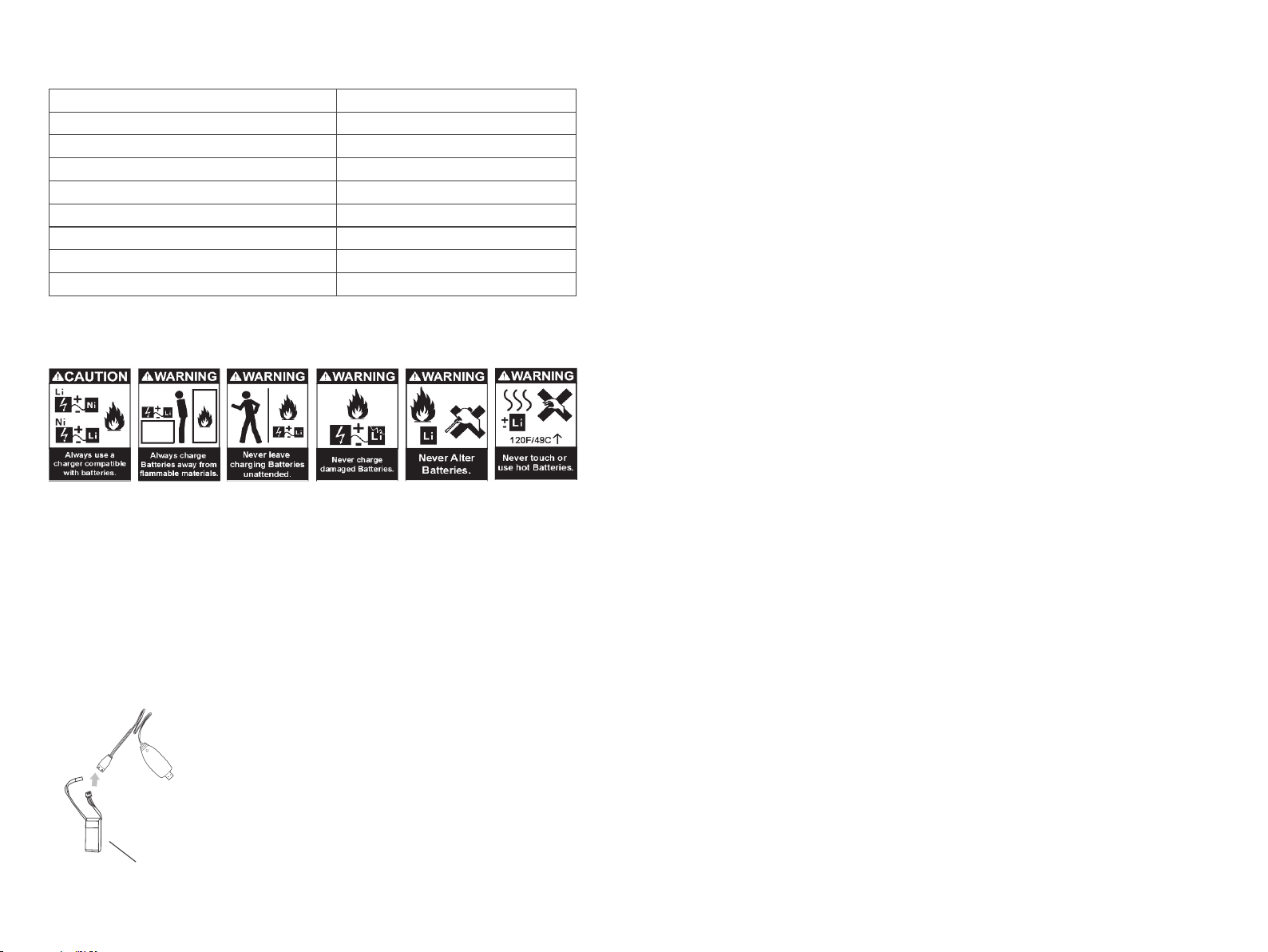
Battery Charging
Warning
1. For maximum safety, please monitor the battery while charging.
2. Please do not allow children to carry out the charging by themselves but ensure
adult supervision is available at all times.
3. Please use the original standard charger of this product for charging. The use of
unknown charger may pose risks of fire and explosion.
4. If available, it is recommended that users use a quality Lipo charger (3s @2A) in
lieu of using the USB charger. This helps to charge the battery at a faster rate.
11.1v 500mAh
-4-
1. To charge the battery, please connect the charger USB plug
into a USB power bank or to a USB port of a computer or a
power adaptor. If no battery is connected, the USB charger
red light will flash.
2. Once the battery is plugged into the USB charger, the
charger's red light is lit to indicate the charging is in
progress.
3. When the battery is fully charged, the USB red light will stay
off.
-3-
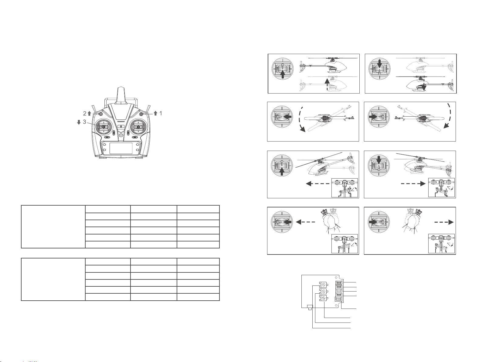
Flight Control Board Interface Diagram
Throttle
Rudder
Throttle up
Rudder left
Elevator up
Aileron left Aileron right
Servo #1
Servo #2
Servo #3
5VS-BUS/PPM
3.3v DSM2/DSMX
Swashplate sensitivity
Swashplate agility
Tail lock sensitivity
Left roll Right roll
Elevator down
Backward
Forward
Rudder righ Right rotati
Left rotation
Ascend Descend
Throttle down
Elevator
Aileron
Initial Flight Setup
If you are not familiar with the controls of the E150, please take a few minutes to get
familiar with them and then try your first flight.
Throttle Curve and Pitch Curve
The above information is for guidance only. You can set the parameters to your
personal preference.
Notes: 3.3V is suitable for DSM receiver and 5V is suitable for FUTABA (S-BUS) J receiver.
Throttle Curve
Pitch Curve
Notice:
1.When the transmitter is turned on and the throttle hold switch is in the ON position,
the transmitter will beep as a warning. The switch should be switched to the OFF
position.
2. When the transmitter is turned on and the 3D switch is in the ON position, the
transmitter will beep. The switch should be switched to the OFF position.
3. When transmitter is turned on and the throttle stick is not at the lowest position the
transmitter will beep as a warning. The throttle stick should then be moved down to
the lowest position.
Position
1
2
3
4
5
0
70
70
70
70
85
85
85
85
85
3D IdleNormal
Position
1
2
3
4
5
35
45
50
65
80
15
32
50
68
85
3D IdleNormal
-6--5-
View from rear of heli View from rear of heli
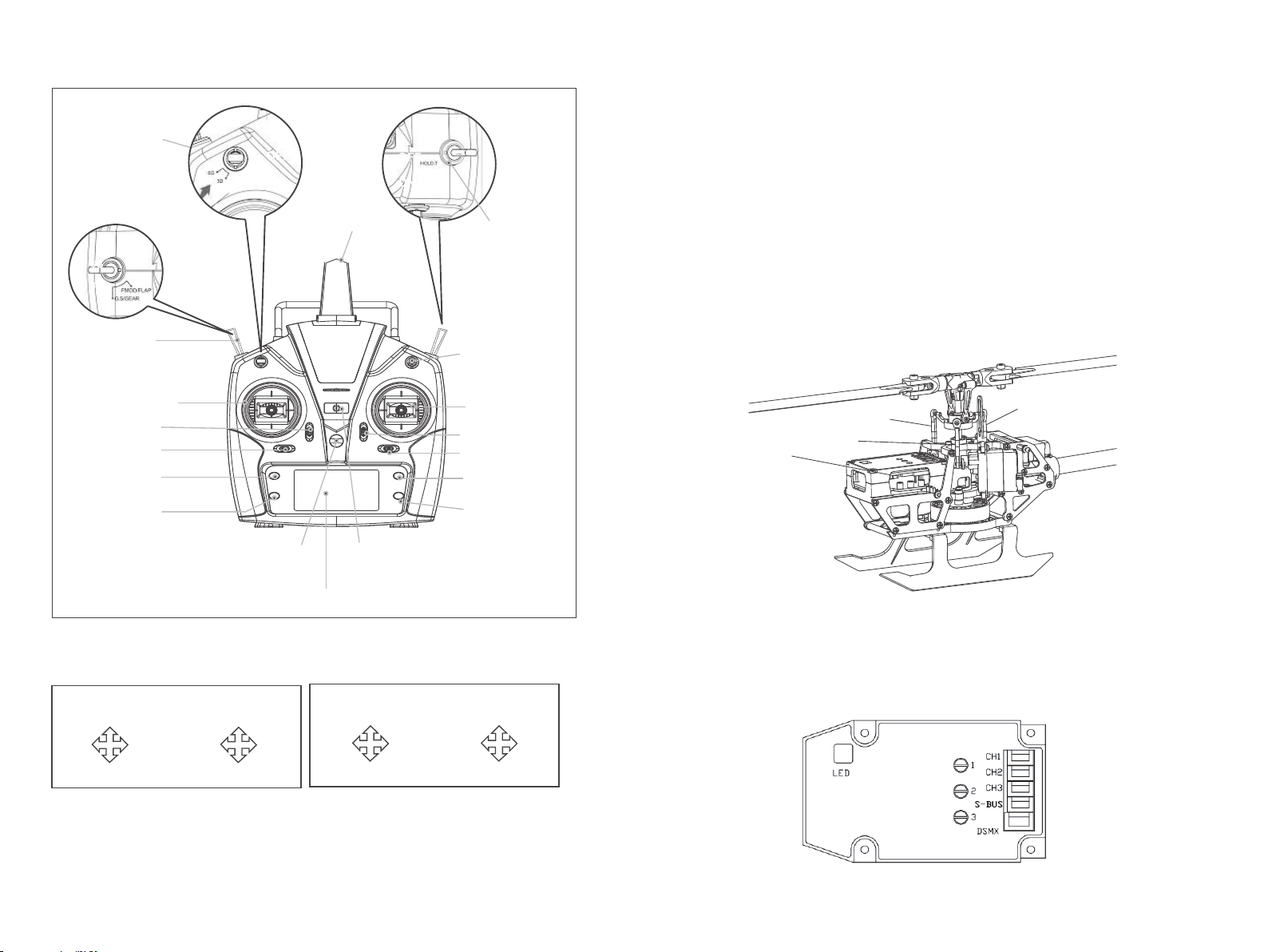
About the Transmitter
6CH/IDLE Switch
Right hand throttle Left hand throttle
5GH/Gyro Switch
TH.HOLD Switch
Antenna
This transmitter supports CCPM 120 degree helicopter mode with 3D 6G
switching. It has high/low rates for two joystick modes, motor cutout switch
(TH.HOLD) and a large screen multi-function LCD display.
Exit
Rudder Trim
Menu
Throttlle/Rudder stick
Throttle trim
Neck strap bracket Power Switch
LED Display
Dual Rates
Aileron/ Elevator
Stick
Page Down
Page Up
Aileron Trim
Elevator Trim
Forward Throttle
Backward
Left
Yaw
Left
Roll
Right
Roll
Throttle
Left
Yaw
Right
Yaw
Right
Yaw
Forward
Backward
Left
Roll
Right
Roll
2) Gyro adjustment
Users can adjust the FBL gyro according to their preference. Use a flat-blade
screwdriver to adjust. Turn clockwise to increase the value, and turn
counterclockwise to decrease the value.
1 Tail lock sensitivity 2 Swashplate agility 3 Swashplate sensitivity.
Flight Control Board Adjustment
1)Servo Centering Adjustment
Note: The product has been adjusted and inspected before leaving the factory.
The user needs to re-adjust the servo centering after replacing the servo or related
accessories.
To ensure safety, disconnect the main motor power during adjustment to avoid
personal injury caused by motor rotation.
If you have one, a swashplate levelling tool allows more accurate adjustment.
First, bind the heli and set the transmitter to 6G self-stabilization mode.
Press the bind button on the flight control board 4 times, the mainboard will flash red
quickly and enter the adjustment mode.
Use the transmitter sticks to adjust the aileron, elevator and rudder servos until the
swashplate is balanced and the blades are at 0 degrees pitch.
After the servo adjustment is completed, press the mainboard bind button to exit.
The red and blue light on the mainboard will be lit.
You can now fly.
Press 4times to enter
servo adjustment mode
Alleron tx stick
Rudder tx stick
Elevator tx stick
-8--7-

Illustrated Parts DiagramTroubleshooting
1
LED on receiver flashes constantly
with no response after transmitter
is switched on.
2
3
4
5
Transmitter is not bound to receiver.
Pairing of the transmitter and receiver
failed.
Carry out pairing (Refer to P.5,
Pairing to Transmitter).
The helicopter has no response after
connecting the battery.
Check whether the transmitter and
receiver are connected to power.
Check the voltage of transmitter and
receiver batteries. Heli battery
connector pins contacts are
degraded.
Open the transmitter, make sure the
batteries connection is good. Replace
and charge transmitter batteries. Make
sure the heli battery connector pins
contacts are good.
When increasing throttle, the main
motor does not start and the LED
on the receiver flashes
continuously.
Low battery voltage, battery
connection is not good.
Replace and charge the battery,
reconnect the battery to the
receiver board.
Helicopter takes off immediately,
after powering up.
The throttle is not at the lowest
position.
Put the throttle stick at the lowest
position before switching on the
transmitter.
Helicopter vibrates or shakes in
flight.
Damaged rotor blades, bent
main shaft and feathering shaft
or blade grips too tight
preventing smooth movement of
the main rotor.
Replace the main rotor blades, bent
main or feathering shafts, loosen the
blade grips.
Problem Cause Solution
Main rotor blades shake during flight.
Feathering shaft or main shaft is
bent. FS screw is not tight
enough. Broken gear in the servo.
The swashplate is worn out.
Replace the feathering shaft. Tighten the
FS screw. Change the main shaft
bearings. Replace the servo. Replace
the swashplate. Replace the tail rotor
blades.
The sound of the main rotor becomes
softer or there is drop in head speed.
Heli battery has low voltage.
Land the helicopter immediately and
charge the battery or change to a
fully charged battery.
Helicopter has no response or
does not fly smoothly. Failure of binding.
Rebind the helicopter and
transmitter. Make sure you place
the helicopter in a steady and
level attitude close to the transmitter.
Helicopter drifts or is not level in
3D or 6G flight modes.
Servos do not go back in to mid-
position or are broken.
Recenter the servo arms. Replace
the applicable servo.
Tail does not lock in 6G mode. Helicopter requires calibration in
6G mode.
Refer to 6G mode calibration procedure.
Helicopter yaws counter clockwise
when taking off.
Tail motor lacks power. Loose
tail rotor. Tail motor damage.
Check the tail rotor and the motor shaft.
If loose, replace the tail rotor. Replace
the tail motor.
Helicopter power is erratic or speed
governor has abnormal sound.
Power Distribution Board is faulty
or has poor contacts.
Check the connectors.
Replace the Power Distribution
Board.
Servo #1
Servo #3
Servo #2
-10-
-9-

Illustrated Parts List Spare Parts List
Notice for beginners:
1.Please fly with an instructor until you are confident enough.
2.Before flying the model for the first time, you need to fully understand all of
the functions provided by the transmitter and the responses of all of the
switches.
3.Do not attempt to fly in 3D mode yet. Practice hovering and flying in 6G mode
until you are familiar with it. Then you can practice hovering and flying in 3D
mode. Once you are familiar with these two modes you can progress to
practicing inverted flight with an instructor.
4.Practicing inverted hovering and inverted flight will build a solid foundation
towards achieving proficiency in 3D flying.
5.This model is not a toy and it can cause damage to people and property. It is
recommended that you practice with a simulator on a computer before doing
real 3D flying with this model to minimize damage.
NO. PART NAME QUANTITY
1
2
3
4
5
6
7
8
9
10
11
12
13
14
15
16
17
18
19
20
21
22
23
24
25
26
27
28
29
30
31
32
33
1
2
2
2
2
1
3
1
2
1
2
1
1
1
1
1
1
1
4
1
1
1
1
1
1
1
1
1
1
1
2
1
1
Main Rotor Head
Main Grip Feathering Shaft Set
Main Blade Grip Set
Main Blade Set
Primary Linkage Set
Swashplate
Secondary Linkage Set
Servo
Main Shaft Set
Servo Mounting Plate
Canopy Mounting Posts
Main Motor
Main Shaft Bearing Mount
Metal Frame Plate A
Metal Frame Plate B
Tail Boom Mount
Main Shaft to Motor Connector
Landing frame Set
Carbon Fiber Side Frame Set
Landing Skid Set
Flight Control Unit Box
Integrated Flight Control Board
Power Distribution Board (PDB)
Anti Rotation Bracket
Battery
Canopy
Tail Boom
Tail Fin Set
Tail Motor Mount
Tail Motor
Tail Rotor
USB Charger
Radio Control
Part No: 2.32.01.E150-001
Part Name: Main Rotor Head
Part No: 2.32.01.E150-003
Part Name: Main Blade Grip Set
Part No: 2.32.01.E150-004
Part Name: Main Blade Set
Part No: 2.32.01.E150-006
Part Name: Swashplate
Part No: 2.32.01.E150-008
Part Name: Servo
Part No: 2.32.01.E150-009
Part Name: Main Shaft Set
Part No: 2.32.01.E150-010 Part
Name: Servo Mounting Plate
Part No: 2.32.01.E150-012
Part Name: Main Motor
Part No: 2.32.01.E150-014 Part
Name: Metal Frame Plate A
Parit No: 2.32.01.E150-015 Part
Name: Metal Frame Plate B
Part No: 2.32.01.E150-016
Part Name: Tail Boom Mount
Part No: 2.32.01.E150-017
Part Name: Main Shaft to
Motor Connector
Part No: 2.32.01.E150-002
Part Name: Main Grip
Feathering Shaft Set
Part No: 2.32.01.E150-005
Part Name: Primary Linkage
Set
Part No: 2.32.01.E150-007
Part Name: Secondary Linkage
Set
Part No: 2.32.01.E150-011
Part Name: Canopy
Mounting Posts
Part No: 2.32.01.E150-013 Part
Name: Main Shaft Bearing
Mount
Part No: 2.32.01.E150-018 Part
Name:Landing frame Set
Part No: 2.32.01.E150-019
Part Name: Carbon Fiber
Side Frame Set
Part No: 2.32.01.E150-020
Part Name: Landing Skid Set
Part No: 2.32.01.E150-21
Part Name: Flight Control Unit Box
Part No: 2.32.01.E150-22
Part Name: Integrated Flight
Control Board
Part No: 2.32.01.E150-23 Part
Name: Power Distribution
Board (PDB)
Part No: 2.32.01.E150-24
Part Name: Anti Rotation
Bracket
Part No: 2.32.01.E150-25
Part Name:Battery
Part No: 2.32.01.E150-26
Part Name:: Canopy
Part: No: 2.32.01.E150-27
Part Name: Tail Boom
Part No: 2.32.01.E150-28
Part Name: Tail Fin Set
Part No: 2.32.01.E150-29
Part Name:Tail Motor Mount
Part No: 2.32.01.E150-30
Part Name: Tail Motor
Part No: 2.32.01.E150-31
Part Name: Tail Rotor
Part No: 1.03.04.001
Part Name:USB Charger
Part No: 2.03.01.T6-001
Part Name: Transmitter
-12-
-11-
Table of contents
Other Eachine Toy manuals


