Eachine E150 User manual

Table of Catalog
Introduction
Item List
Notice
Warning
Additional Safety Precautions and Warnings
Helicopter Parameters
Warning and the Guide of Battery Usage
Battery Charging
Notice Before Flight
Bind With Transmitter
Throttle Curve and Pitch Curve
Initial Flight
Receiver Interface Diagram
About the Transmitter
Flight Battery Installment
Troubleshooting
Exploded View
Accessory List
Accessories List
1
1
2
2
2
3
3
3
4
4
5
6
6
7
8
9
10
11
12

Notice
All instructions, warranties and other collateral documents are subject to change at
the sole discretion of our company. For up-to-date product literature, please visit
www.eachine.com.
Warning
Read the ENTIRE user manual to become familiar with the features of the product
before operating. Failure to operate the product correctly can result in damage to
the product, personal property and cause serious injury. This is a sophisticated
hobby product. It must be operated with caution and common sense and requires
some basic mechanical ability. Failure to operate this product in a safe and
responsible manner could result in injury or damage to the product or other
properties. This product is not intended for use by children without direct adult
supervision. This manual contains instructions for safety, operation and
maintenance. It is essential to read and follow all the instructions and warnings in
the manual,prior to assembly,setup or use,in order to operate correctly and avoid
damage or serious injury.
Additional Safety Precautions and Warnings
1.Age Recommendation: Not for children under 14 years. This is not a toy.
2.Always operate your model in open spaces away from full-size vehicles, traffic and
people.
3.Follow the operation notice, warning and any support equipment (charger, battery,
etc) carefully.
4.Keep away from any chemicals; keep children away from any small parts and
electrical equipment.
5.Always keep away from water, especially for this product don't have water- proof
function; It will be damaged by moisture.
6.Never place any portion of the model in your mouth as it could cause serious injury
or even death.
7.Never operate your model with low voltage transmitter batteries.
Gift Box
Sturdy PVC protective box
User Manual
Helicopter
Transmitter
Charger
Battery 11.1v 500mah 30C
Cross Screwdriver / Hex Wrench
Main Blade
Tail Blade
1
2
3
4
5
6
7
8
9
10
1
1
1
1
1
1
1
1
2
1
Item List
NO. PARTS QUANTITY
Introduction
This is a super classic helicopter with excellent fight performance. Flybarless
design, decrease resistance of rotor head. Quote to aerodynamics, the blades
can supply strong power and keep stability. Using the latest technology of new
gyro type, this helicopter is compatible with 3D and 6G modes. You can make a
variety of stunts in 3D mode. 6G mode is especially suitable for beginners.
Once you have flown this mini helicopter, you will find other similar mini
helicopters are much inferior. This is a incomparable and popular helicopter.
Once it has been set up correctly, beginners will find it is very easy to fly.
They can master or quickly learn new moves. The built-in ‘rescue’ or upright
function in 6G mode (if set up properly), can save the helicopter in most cases.
The detailed instructions in this manual will help you understand more about
the product. Please read it before operating your helicopter. It may help you to
save both time and money due to incorrect settings etc.
-2--1-

Helicopter Parameters
Warning and the Guide of Battery Usage
Notice Before Flight
Battery Charging
Length
Height
Weight
Length of Main Propeller
Diameter of Tail Propeller
Battery Specification
Flight Time
Main Brushless Motor
Brushless Tail Motor
330 mm
105mm
181g
355 mm
56mm
11.1v 500mAh 30C
7-9 Min
2507
1103
To ensure safety, please use the included supplied standard charger.
1.To charge the battery, please connect the charger USB
plug into a USB plug pack or to a USB port of a computer
or a plug pack. If no battery is connected, the USB charger
red light will flash.
2.Once the battery is plugged into the USB charger, the
charger's red light is lit to indicate the charging is in
progress.
3.When the battery is fully charged, the USB red light will
stay off.
1.Ensure the batteries for both the tx and helicopter are fully charged.
2.Before turn on the TX, please make sure the throttle control is at the lowest
position and the TH.HOLD and 3D mode switches are in the back position
(back cover direction).
3.Make sure the TX has paired with helicopter. If not or please carry out the
pairing process.
4.Please turn on the TX first, then connect the battery to the helicopter and wait
until it paired with TX. When turn off, please unplug the power from the
helicopter first, and then turn off the TX.
5.Keep away from people, cars, high-tension power lines and water sources such
as ponds, lakes, rivers etc.
Bind With Transmitter
If you have the RTF package, the helicopter ia already paired by the factory.
However, if you need to pair again, please follow the following steps.
1.First turn on the transmitter and make sure the throttle stick is at the bottom
position, 3D IDLE switch is in the OFF position.
2.Remove the canopy for activating the binding switch.
3.Apply power to the helicopter, the red led flashes slowly, press the code button
for 1 second, then the red lamp will go out and get ready for pairing.
4.When the red and blue lights turn on solid, the pairing has been successful.
5.While carrying out the pairing, ensure there are no other transmitters are
operating nearby to avoid unintended pairing.
Tips: This product is compatible with all FUTABA 2.4GHZ S-FHSS transmitter.
WARNING:It is highly recommended to use the supplied charger to charge the
battery.
Notice:When the battery voltage is lower than 11.1V, the lithium battery may be
damaged, and may be no longer correctly charged. When the battery voltage is lower
than 11.1V during a flight, the main ESC drops the head speed significantly. Please
land immediately and charge the battery as soon as possible.
Warning
1.For maximum safety, please monitor the battery while charging.
2.Please do not allow children to carry out the charging by themselves but ensure
adult supervision at all times.
3.Please use the original standard charger of this product for charging. The use of
unknown charger may pose risks of fire and explosion.
4.If available, it is recommended that users use own Lipo 3s @2A charger in lieu of
using the USB charger. This helps to charge the battery at a much faster rate.
11.1v 500mAh
-4--3-

Initial Flight
Receiver Interface Diagram
Throttle
Rudder
Throttle up
Rudder left
Elevator up
Aileron left Aileron right
Servo #1
Servo #2
Servo #3
5VS-BUS/PPM
3.3v DSM2/DSMX
3.3v DSM2/DSMX
Swash plate sensitivity Swashplate agility
The lock tail sensitivity
Left roll Right roll
Elevator down
Backward
Forward
Rudder righ Right rotati
Left rotation
Ascend Descend
Throttle down
Elevator
Aileron
If you are not familiar with the controls of the E150, please take a few minutes to get
familiar with them and then try your first flight.
Throttle Curve and Pitch Curve
The above information is for your reference only, you can set the parameters to your
demand.
Notes: 3.3V is suitable for DSM receiver and 5V is suitable for FUTABA (S-BUS) J receiver.
Throttle Curve
Pitch Curve
Notice:
1.When the transmitter is turned on and the throttle hold switch is in the ON position,
the transmitter will beep as a warning. The switch should be switched to the OFF
position.
2.When the transmitter is turned on and the 3D switch is in the ON position, and the
transmitter will beep. The switch should be switched to the OFF position.
3.When transmitter is turned on and the throttle stick is not in the lowest position the
transmitter will beep as a warning. The throttle stick should then be pulled down to
the lowest position.
Position
1
2
3
4
5
0
70
70
70
70
85
85
85
85
85
3D IdleNormal
Position
1
2
3
4
5
35
45
50
65
80
15
32
50
68
85
3D IdleNormal
-6--5-

About the Transmitter Flight Battery Installment
6CH/IDLE Switch
Right hand throttle Left hand throttle
5GH/Gyro Switch
Throttle Rudder Joystick
TH.HOLD Switch
Antenna
This transmitter supports CCPM 120 degree helicopter dedicated transmitter,
with 3D 6G switching high/low rudder capacity for two joystick modes, main
cutout switch (TH.HOLD) and other modes, large screen LCD display
multi-function transmitter.
Exit
Menu
Rudder Fine- tuning
Throttle Fine- tuning
Flying Rings Power Switch
LED Display
Servo Scale
Aileron/ Elevator
Joystick
Page Down
Page Up
Aileron Fine-tuning
Elevator Fine-tuning
Forward Throttle
Backward
Left
Steering
Left
Sideward
Right
Sideward
Throttle
Left
Sideward
Right
Sideward
Right
Steering
Forward
Backward
Left
Steering
Right
Steering
2) Sensitivity adjustment
Users can adjust different lock perception according to their own needs, use a
flat-blade screwdriverto adjust, turn clockwise to increase the lock perception,
and turn counterclockwise to decrease thelock perception.
1 Lock tail sensitivity 2 Swashplate perception 3 Swashplate sensitivity.
1)Debugging pitch of thread
Explanation: The product has passed the inspection before leaving the factory,
the user needs tore-adjust the pitch of thread after replacing the steering gear
or related accessories.
To ensure safety, disconnect the main motor power cord during commissioning
to avoid personalinjury caused by motor rotation during commissioning.
The user comes with a special pitch of thread ruler for helicopters that can be
adjusted more accurately.First, bind the aircraft to the code, and the transmitter
in 6G self-stabilization mode.
Press the code matching key on the flight control board 4 times, the mainboard
will flash red quickly and enter the debugging mode.
Use the transmitter to control the aileron rocker, lift rocker, and direction rocker for
debugginguntil the swashplate is balanced and the blades are at 0 pitch of thread
After the debugging is completed, press the motherboard link key to exit the
debugging, themotherboard will resume the red light and the blue light will be on,
then you can fly.
Press 4times to enter
debug mode
Alleron joystick debug ging
Directiong joystick debug ging
Lifting rocker debug ging
-8--7-

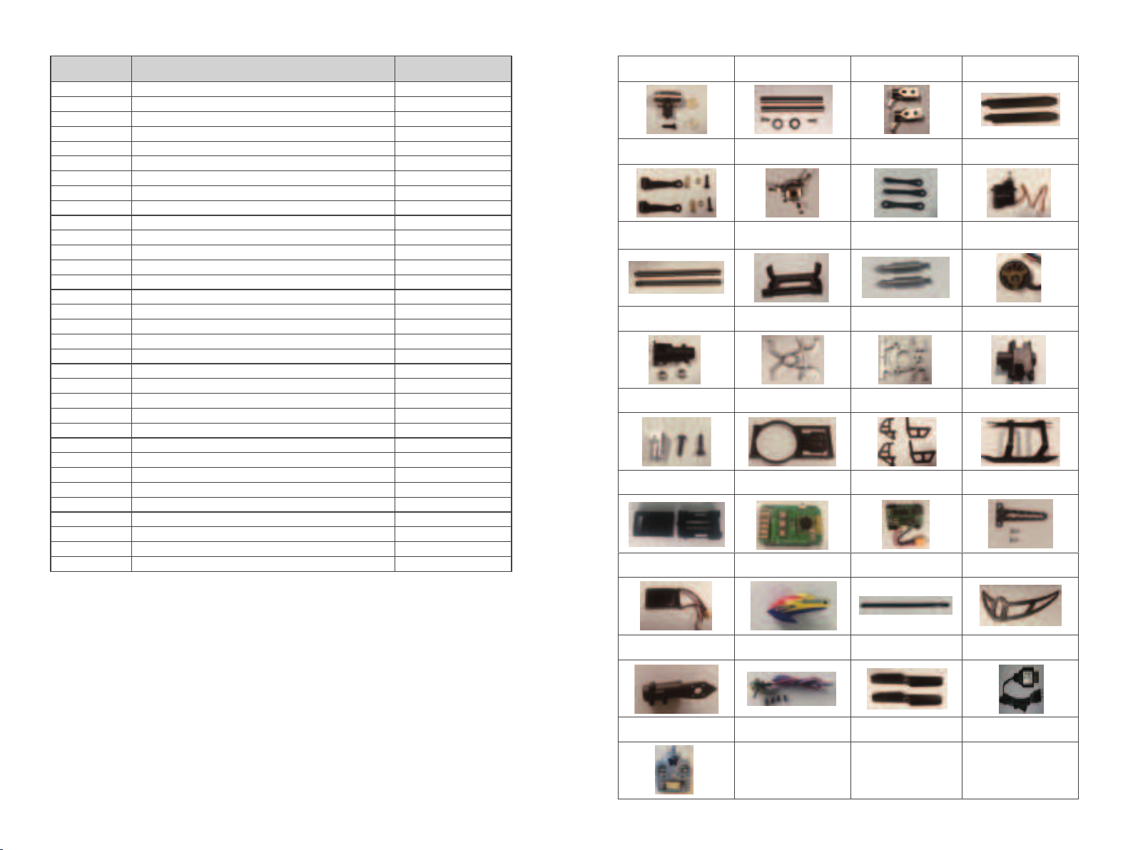
Exploded ViewTroubleshooting
1
LED on receiver flashes constantly
with no responses after connecting
batteries to transmitter.
2
3
4
5
Transmitter is not bound to receiver.
Pairing of the transmitter and receiver
failed.
Re-pair (Refer to P.5, Programming
your Transmitter).
The helicopter has no response after
connecting batteries to receiver.
Check whether the transmitter and
receiver connecting to power;
check the voltage of transmitter and
receiver; Battery pole flake contact
is not good.
Open the transmitter, make sure the
batteries connecting is good Replace
and charge transmitter batteries Make
sure the battery pole flake contact is
good.
When increasing throttle, the main
motor does not start and the LED
on the Receiver flashes constantly.
Low battery voltage, batteries
connection is not good.
Replace and charge the batteries,
reconnect the batteries to the
receiver board.
Helicopter takes off immediately,
once the batteries and receiver
connected.
Didn't put the throttle to the lowest. Put the throttle pole at thelowest
position before open the transmitter.
Helicopter vibrates or shakes in
flight.
Damaged rotor blades, bent main
and FS shafts or blade grips too
tight causing the main rotor
movement not smoothly.
Replace the main rotor blades, bent
main or feathering shafts, loosen the
blade grips.
Problem Cause Solution
Main rotor blades shake during flight.
Feathering shaft or main shaft is
bent. FS screw is not tight enough.
possible broken gear in the servo,
causing shakes. The loose between
the swashplates.
Replace the lateral axis. Tighten the
lateral axis screw. Change the Bearing.
Remove the servo, and clear debris.
Compress the swash plates. change the
tail rotor blades.
The sound of the main rotor becomes
softer or drop in head speed.
Low battery voltage of helicopter.
Land the helicopter immediately and
charge the battery or change to a
fully charged battery.
Helicopter has no reaction or does
not fly smoothly. Failure of binding.
Rebind the helicopter and transmitter,
make sure you place the helicopter at
a steady level close to the transmitter.
3D/6G model helicopter appeared
yaw.
Swashplate servos do not go back
in to mid-position or broken. Recenter the servo arms.Replace the
servo.
Tail does not lock in 6G mode. Helicopter requires to calibrate in
6G mode.
Refer to 6G mode calibration procedure.
Helicopter took off spin to the left. Tail motor power shortage loose
blades Tail motor damage.
Check with the tail rotor blades and
the motor shaft, If loose replacement
tail rotor blade. Motor damage Replace
the tail motor.
Helicopter power is turned supreme
speed governor electric sound.
Brushless speed governor fault or
poor contact.
Check the connectorsreplace speed
governor.
Servo #1
Servo #3
Servo #2
-10--9-

Accessory List Accessories List
Notice for beginners:
1.Please fly with an instructor until you are confident enough.
2.Before flying the model for the first time, you need to fully understood all of
the functions provided by the transmitter and the responses of all of the
switches.
3.Don't attempt to fly in 3D mode yet. Practice flying and hovering in 6G mode
until you are familiar with it. Then you can practice flying and hovering flight
under 3D mode. Once you are familiar with these two modes you can vary
out practicing inverted flight with an instructor.
4.Practice hovering flight of inverted moves to build a foundation that making
more brilliant flying.
5.This model is not a toy and it can cause damages to people and property.
If unsure, it is recommended that you practice with a simulator on a
computer before doing real 3D fly with this model to minimize the damage.
NO. PARA NAME QUANTITY
1
2
3
4
5
6
7
8
9
10
11
12
13
14
15
16
17
18
19
20
21
22
23
24
25
26
27
28
29
30
31
32
33
1
2
2
2
2
1
3
1
2
1
2
1
1
1
1
1
1
1
4
1
1
1
1
1
1
1
1
1
1
1
2
1
1
Main Rotor Head
Main Grip Blade Shaft Set
Main Blade Grip Set
Main Blade Set
Primary Linkage Rod Set
Swashplate
Secondary Linkage Set
Servo
Spindle Set
Servo Mounting Plate
Metal Canopy Mounting Post
Main Motor
Main Shaft Bearing Mount
Metal Frame Plate A
Metal Frame Plate B
Tail Boom Fixator
Connecter set of Spindle and Motor
Landing frame Set
Carbon Fiber Side Frame Set
Landing Skid Set
Flight Control Unit box
Integrated Flight Control Board
Power Distribution Board (PDB)
Swashplate seat
Battery
Canopy
Tail Boom
Horizontal Tail Fin Set
Tail Motor Mount
Tail Motor
Tail Rotor
USB Charger
Radio Control
Part No: 2.32.01.E150-001
Part Name: Main Rotor Head
Part No: 2.32.01.E150-003
Part Name: Main Blade Grip Set
Part No: 2.32.01.E150-004
Part Name: Main Blade Set
Part No: 2.32.01.E150-006
Part Name: Swashplate
Part No: 2.32.01.E150-008
Part Name: Servo
Part No: 2.32.01.E150-009
Part Name: Spindle Set
Part No: 2.32.01.E150-010
Part Name: Servo Mounting Plate
Part No: 2.32.01.E150-012
Part Name: Main Motor
Part No: 2.32.01.E150-014
Part Name: Metal Frame Plate A
Parit No: 2.32.01.E150-015
Part Name: Metal Frame Plate B
Part No: 2.32.01.E150-016
Part Name: Tail Boom Fixator
Part No: 2.32.01.E150-017
Part Name: Connecter set of
Spindle and Motor
Part No: 2.32.01.E150-002
Part Name: Main Grip Blade
Shaft Set
Part No: 2.32.01.E150-005
Part Name: Primary Linkage
Rod Set
Part No: 2.32.01.E150-007
Part Name: Secondary Linkage
Set
Part No: 2.32.01.E150-011
Part Name: Metal Canopy
Mounting Post
Part No: 2.32.01.E150-013
Part Name: Main Shaft Bearing
Mount
Part No: 2.32.01.E150-018
Part Name:Landing frame Set
Part No: 2.32.01.E150-019
Part Name: Carbon Fiber
Side Frame Set
Part No: 2.32.01.E150-020
Part Name: Landing Skid Set
Part No: 2.32.01.E150-21
Part Name: Flight Control Unit box
Part No: 2.32.01.E150-22
Part Name: Integrated Flight
Control Board
Part No: 2.32.01.E150-23
Part Name: Power Distribution
Board (PDB)
Part No: 2.32.01.E150-24
Part Name: Swashplate seat
Part No: 2.32.01.E150-25
Part Name:Battery
Part No: 2.32.01.E150-26
Part Name:: Canopy
Part: No: 2.32.01.E150-27
Part Name: Tail Boom
Part No: 2.32.01.E150-28
Part Name: Horizontal Tail Fin Set
Part No: 2.32.01.E150-29
Part Name:Tail Motor Mount
Part No: 2.32.01.E150-30
Part Name: Tail Motor
Part No: 2.32.01.E150-31
Part Name: Tail Rotor
Part No: 1.03.04.001
Part Name:USB Charger
Part No: 2.03.01.T6-001
Part Name: Transmitter
-12--11-
Table of contents
Other Eachine Toy manuals
Popular Toy manuals by other brands

MULTIPLEX modell
MULTIPLEX modell DG 300 Elan Building instructions

Techno Gears
Techno Gears RC MONSTER Truck instruction manual

L. G. B.
L. G. B. F7-B Instruction

HUSAN
HUSAN MONEY SAFE quick start guide

Eduard
Eduard MiG-15 Landing Flaps: 48420 quick start guide

Kyosho
Kyosho MINI-Z Racer MR-02 RM Type instruction manual