Product Manual Rosa Switch
EAE KNX Rosa Switch Rosa Switch PB
©EAE Technology www.eaetechnology.com Page 5 / 26
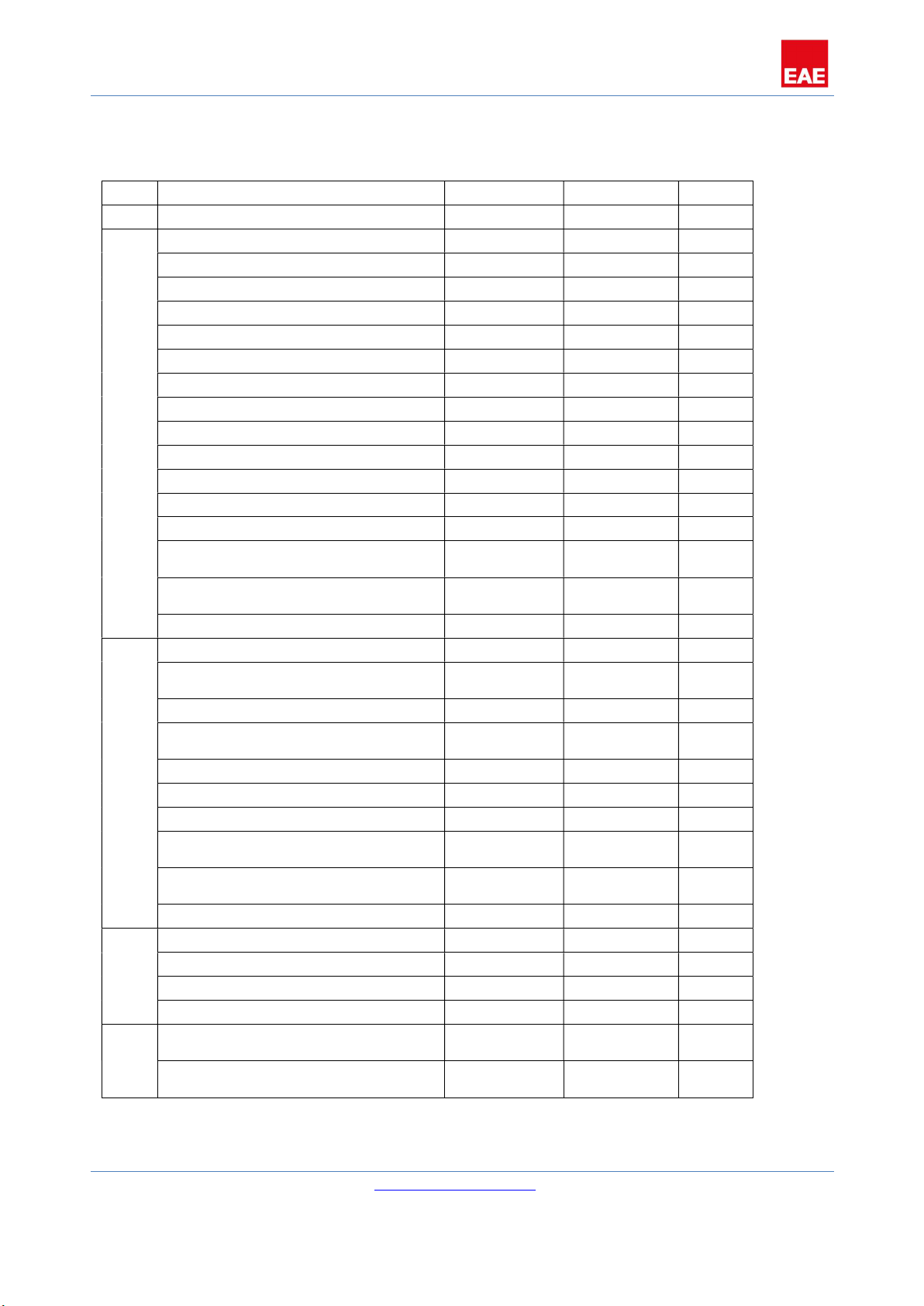
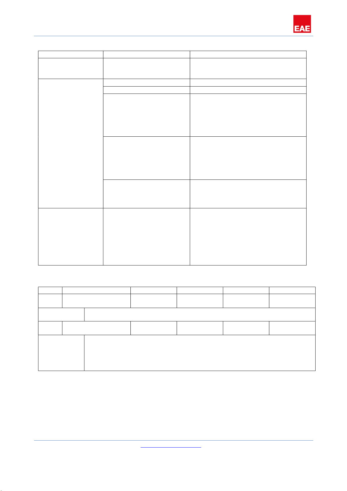
3. Communication Object Table
No. Object Name Function Number of Bits
Flags
0 General, operation Active 1 CT
1 Rocker 1, switch On/Off 1 CWT
Rocker 1, shutter Up/Down 1 CWT
Rocker 1, value [0,1] Send 1 CWT
Rocker 1, value [0…255] Send 8 CWT
Rocker 1, value [0…65535] Send 16 CWT
Rocker 1, value [-32768…32768] Send 32 CWT
Rocker 1, value [0…4294967295] Send 64 CWT
Rocker 1, value.temperature Send 64 CWT
TouchButton 1, switch On/Off 1 CWT
TouchButton 1, shutter Up/Down 1 CWT
TouchButton 1, value [0,1] On/Off 1 CWT
TouchButton 1, value [0...255] Send 8 CWT
TouchButton 1, value [0..65535] Send 16 CWT
TouchButton 1, value [-
32768…32768]
Send 32 CWT
TouchButton 1, value
[0…4294967295]
Send 64 CWT
TouchButton 1, value.temperature Send 64 CWT
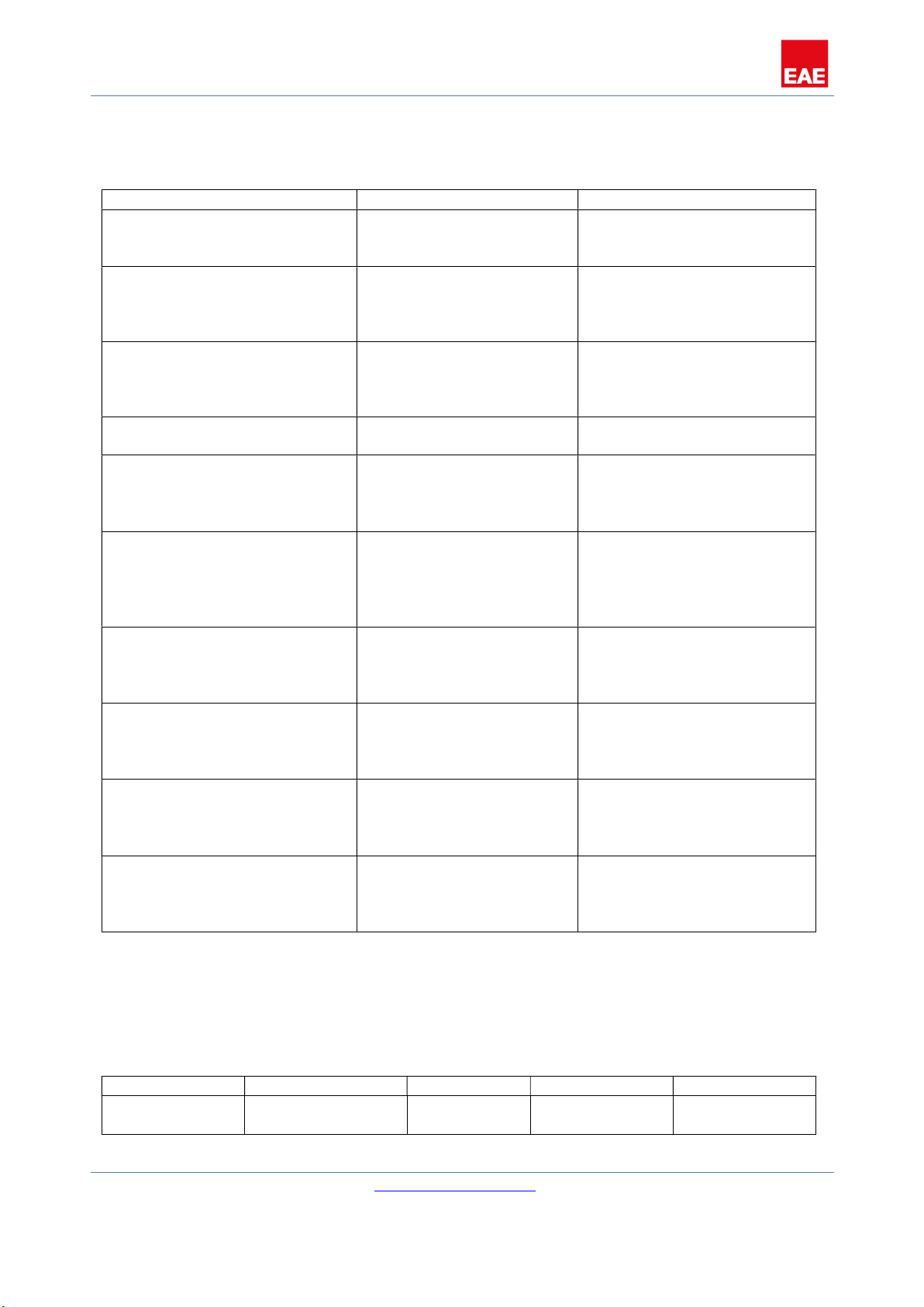
2 Rocker 1, dimming Send 4 CWT
Rocker 1, shutter Stop/Lamella
Adj
1 CWT
TouchButton 1, dimming Send 4 CWT
TouchButton 1, shutter Stop/Lamella
Adj
1 CWT
TouchButton 1, value [0,1] On/Off 1 CWT
TouchButton 1, value [0…255] Send 8 CWT
TouchButton 1, value [0…65535] Send 16 CWT
TouchButton 1, value [-
32768…32768]
Send 32 CWT
TouchButton 1, value
[0…4294967295]
Send 64 CWT
TouchButton 1, value.temperature Send 64 CWT
3 Rocker 1, shutter Top Position 1 CWT
Rocker 1, status Top Position 1 CWT
TouchButton 1, shutter Top Position 1 CWT
TouchButton 1, status Top Position 1 CWT
4 Rocker 1, shutter Bottom
Position
1 CWT
TouchButton 1, shutter Bottom
Position
1 CWT