Eagle Premier Series Product manual

1
REVISED: 2012-09-14 FIRMWARE VERSION >= 2.32
Premier Series Monitor
RP-1000/RP-1200
TECHNICAL REFERENCE
MANUAL
EAGLE MICROSYSTEMS, INC.
366 Circle of Progress
Pottstown, PA 19464
PHONE: 610-323-2250 FAX: 610-323-0114
www.eaglemicrosystems.com

2
The RP-1000/1200 monitors a pH, ORP, or a fluoride probe and an optional
residual probe. Up to four set points (two for each input) are provided. An internal
scaled 4-20mA signal is provided for remote monitoring of the pH, ORP, or a fluoride
probe. A second analog output for remote monitoring of the residual is available as an
option.
PUSHBUTTON LEGEND SUMMARY
SET From the main operating screen, enter SETUP menus.
ESC Return to the last menu.
UP Increase a value (i.e., set point) or select the next parameter.
DWN Decrease a value (i.e., set point) or select the last parameter.
ADJ Adjust the value of the parameter displayed.
ALM Go to the alarm set point menu.
CAL Go to the calibration menu.
ACK Acknowledge the alarm condition(s).
CLEAR Temporarily clear the alarm condition(s).
x:y Set point x indicates a low or high set point (L or H), and y indicates the
relay number (1,2 or 3)
ZRO Enter the cell input zero menu.
SPAN Enter the cell span input set menu.
PO1 Calibrate the PO1.
4mA Set 4mA PO1 or PV1 point.
20mA Set 20mA PO1 or PV1 point.
SCREENS
All screens other than the main operating
screens are formatted where the top line
displays a parameter name, value & units. The
bottom line displays a pushbutton legend to aid
in guiding one through the instrument setup and
operation.
LOW 5.00 ppm
UP| DWN| SET
VALUE
PARAMETER
NAME
PUSHBUTTON LEGEND
UNITS
TYPICAL SCREEN

3
MAIN SCREEN
The basic operation of the RP-1200 is
a simple indication of a pH, ORP,
fluoride, or ammonia probe output.
The screen to the right shows the pH
label, value, and units (if needed). On
the bottom line is a fifty-element bar
graph that is represents the analog
output.
An optional residual probe can be
displayed on the main screen.
•Pressing the SET pushbutton prompts the operator to enter a password.
•If the password entered is correct and before the unit displays the METER
SETUP menu.
pH 7.00
|||||||||| | SET
VALUE
LABEL
PUSHBUTTON LEGEND
UNITS (if
needed)
PH, ORP,
FL, NH3
BARGRAPH
pH 7.00
RE 0.00 ppm SET
VALUE
LABEL
PUSHBUTTON LEGEND
UNITS
PH, ORP, FLUORIDE w/ RESIDUAL
RESIDUAL

ADVANCED PARAMETER MENU
To select the instrument as a meter (UPC1000), gas detector (GA-1000), meter, or
residual analyzer (RA-1000), do as follows: From the current main operating screen,
press SET and enter the password “1?1” and press the ENT pushbutton. Alternatively, if
one is in the setup menu, press the right most pushbutton until the password screen is
displayed, enter the password “1?1” and press the ENT pushbutton.
Parameter: MODE
Press the ADJ pushbutton to set the choice to METER (if not set).
Parameter: TEMPERATURE
Selects the unit of the temperature display as either degrees Celsius or Fahrenheit.
Parameter: BUZZER
Enables (ON) or disables (OFF) the audible alarm.
Parameters: K1, K2, K3
Sets the operating mode of the selected relay.
K1-K4 ENERGIZED DE-ENERGIZED
OFF NEVER ALWAYS
LOW INPUT <=
SP INPUT > SP
LOW /w
ACK INPUT <=
SP INPUT > SP OR Acknowledged by USER
HIGH INPUT >=
SP INPUT < SP
HIGH /w
ACK INPUT >=
SP INPUT < SP OR Acknowledged by USER
After one is finished, press the ESC pushbutton to return to the main operating screen.
K1 – K3 are used for pH, fluoride, NH3, or ORP set points.
4

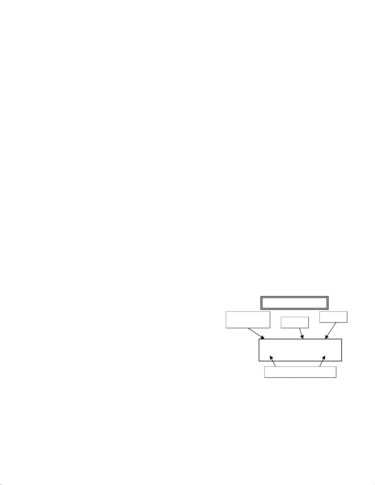
METER (RESIDUAL/ORP/pH/FLUORIDE) SETUP
From the main operating screen, press the SET pushbutton and enter the password
(default 000). Press ENT to, if a valid password was entered, enter the main setup
menu; three choices are shown: CAL, ALM and PARM. Press ESC to return to the main
operating screen after several prompts.
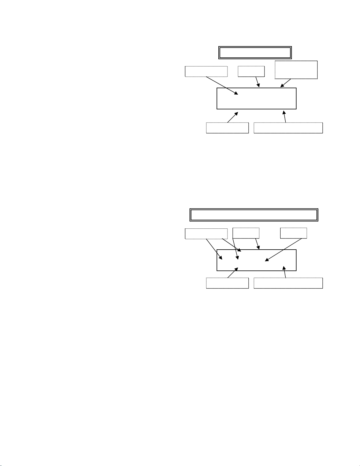
PARAMETER LIST UNDER THE PARM MENU
Press PARM to enter the parameter setup.
Parameter: PV1 ENABLE (RES ENABLE)
Enables the residual display on the main screen (the bar graph is replaced). The probe
interfaces to the PV1 + input and an internal 24V source. Set this parameter to OFF
(NO).
Parameter: PV1 DP (RES DP)
Selects the residual decimal point…
Parameter: PV1 FS (RES FS)
Sets the residual full-scale… This also sets the optional second 4-20mA analog output
full-scale value.
Parameter: INPUT
Selects the PV3 probe input as an ORP, FLR (fluoride), pH, etc. Other labels that are
specific to the probe input type will change accordingly.
Parameter: ORP FS, FLR FS, pH FS, NH3 FS, or TTL FS.
Sets the value that represents an analog output of 20mA.
Parameter: ORP ZERO, FLR FS, pH ZERO, NH3 ZERO, or TTL ZERO
Sets the value that represents an analog output of 4mA.
Parameter: PROBE DAMP
This parameter sets the probe damping (filtering). The settings are OFF, 1s, 2s, 3s, 5s,
10s, 20s, 30s, 45s, 60s, 2m, 3m, 5m, 10m, 15m, 20m, 30m, 60m. This value is the time
it takes to reach 95% of the final probe value. Multiplying the time by 4 yields the time it
takes to achieve 100% of the final probe value (i.e., It takes about 8s to achieve a 100%
value on the display when the 2s setting is selected).
DECIMAL POINT
S2, located on the RA-1000-CPU board, sets the decimal point as follows:
SWITCH, S2 pH ORP FLR (Fluoride)
A 0.0 0 0.00
B 0.0 0 0.00
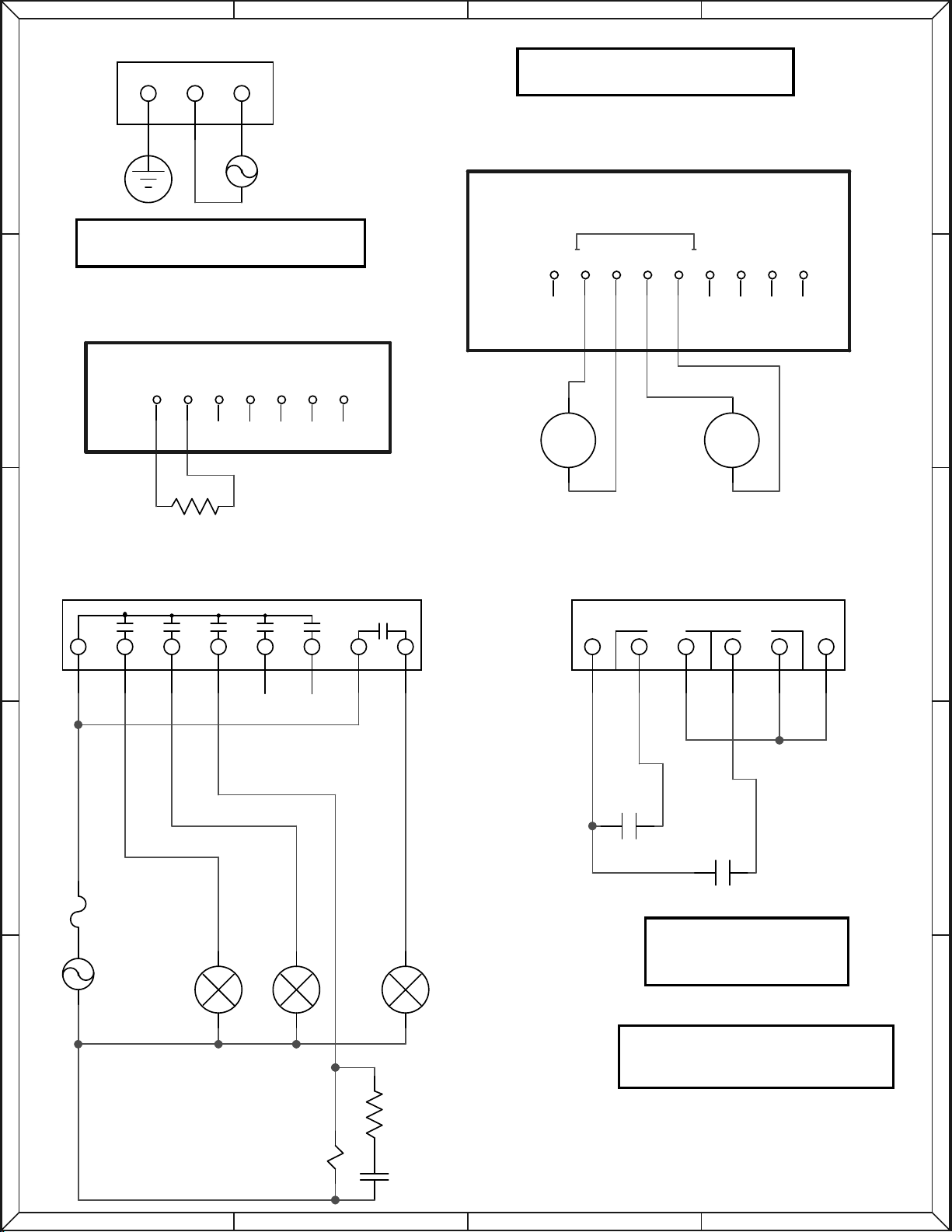
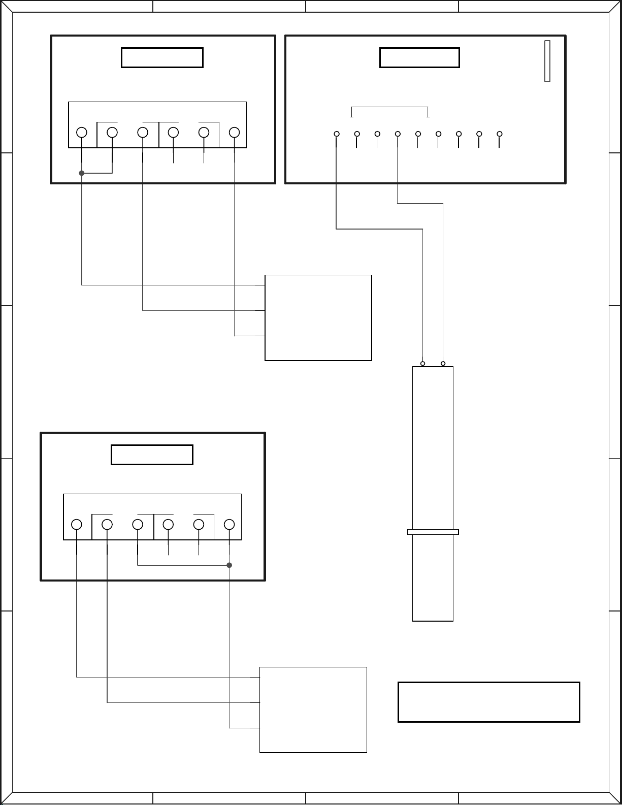
The decimal point for the CL2 total probe is selected by the PV1 DP setting. This
application typically contains a total and free CL2 probe. The latter is connected to PV1
& the 24V source (see diagrams).
5

ALARM (ALM) SET POINTS
Press the ALM pushbutton under the METER SETUP menu. Up to three, user selectable set points can
be used. Parameters K1, K2, & K3 in the ADVANCED PARAMETER MENU select each set point’s mode
of operation. K1 – K3 are used for pH, fluoride, or ORP set points.
The pushbutton legend has the format, “x:y,” where ‘x’ indicates a low or high set point (L or H) and ‘y’
indicates the relay number (1,2, or 3).
Examples:
L:1 is low-level set point controlling relay 1
H:2 is high-level set point controlling relay 2
ACKNOWLEDGABLE SET POINTS
These are set points in which a screen in the main residual screen is displayed that will require the
operator to decide on one of two choices: ACK or CLEAR.
ACK: The set point relay is de-energized & the buzzer (if enabled) is silenced. The set point alarm will not
appear until reset by the residual input going out of the set point’s active range.
CLEAR: The set point relay is de-energized & the buzzer (if enabled) is silenced. The set point alarm will
appear ten seconds later if the residual input does not go out of the set point’s active range.
NON-ACKNOWLEDGABLE SET POINTS
The relay will energize or de-energized based on the set point’s mode & value. No screen will be
displayed indicating the alarm and the buzzer will not sound.
PASSWORD
After one exits the CALIBRATION menu, one is first prompted to change the stored password. If
one does not want to change the password, press the NO pushbutton. If the YES pushbutton is pressed,
the SET new password screen is entered and now one can set the new password.
CALIBRATION (ALL MODES)
To calibrate from the main operating screen (flow, residual/ORP/pH, or compound loop), press the SET
pushbutton, enter the password (default is 000), and press the CAL pushbutton.
The three selections (other than escape) are as follows:
•PV3: Fluoride/ORP/pH/NH3 input.
•PV1: Residual probe calibration.
•PO1: Fluoride/ORP/pH/NH3 output.
PROBE CALIBRATION (BASIC)
Example is based on a residual probe connected to +24V SRC (+) and the +PV1 input (-).
1. Select PV1 (residual).
2. Zero a 0ppm residual by pressing the ZRO pushbutton.
3. Supply a known residual to the sensor probe and wait for a stable ppm display.
4. Press SPAN to set the known residual value in ppm units. Slew-in the correct value and press
ENT.
5. Repeat if necessary.
6. Exit to the calibrate menu by pressing the ESC pushbutton.
The residual analog input (PV1) can be “normalized” to a 4-20mA generator connected to the PV1 input.
This will not match with the residual probe calibration.
6

7
•Set the mA generator to 4.00mA and press the pushbutton under the ZERO label to set the zero
ppm point. The display should read 0ppm.
•Set the mA generator to 20.00mA and press the pushbutton under the SPAN label to set the span
maximum point. The display should read the same as the PV1 FS parameter.
•If desired, repeat the above to verify calibration. However, the zero and span points are not
interactive so one can skip this step.
•Press the ESC pushbutton to exit to the calibration menu.
CALIBRATION OF pH, ORP or FLUORIDE
Selecting PV3 in the calibration menu will display the screen to the right.
Pushbuttons P1 and P2 set calibration points 1 and 2, respectively.
Pressing RST restores the default calibration values to (P1) 0.2ppm @
140mV & (P2) 2.0ppm @ 84mV. Pressing ESC backs to the calibration
menu.
Calibrate two points following a procedure documented in the probe manufacturer’s manual. P1 (point 1)
should be lower then P2 (point 2).
Fluoride: Do not calibrate from 0.0ppm to 0.1ppm of fluoride, as the probe is quite non-linear below 0.2.
Ammonia: Do not calibrate a zero ammonia value, select 0.01 instead. Calibrate the lower point using P1
and the higher point using P2.
PO1/PO2 (OUTPUT) CALIBRATION
To calibrate the analog output for channel one or two (PO1 or PO2), one must connect either a DMM (mA
input) or other device that can read the PO1/PO2 current output. The device should have, at least,
0.01mA precision. NOTE: PO2 is an optional board installed inside the PS-1000 enclosure.
1. From the calibration menu, press the POx pushbutton to enter the CAL ANALOG OUTPT (output)
screen.
2. Connect the DMM to the analog output that is being calibrated (PO1 or PO2) and press the PO1
or PO2 pushbutton to enter that calibration screen (SET ANALOG OUT).
3. Press the 4mA pushbutton and the mA meter should read around 4.00mA.
4. Use the UP & DOWN pushbuttons to set the output to exactly 4.00mA and press set when done.
This is the zero point.
5. Press the 20mA pushbutton; the mA meter should read around 20.00mA.
6. Use the UP & DOWN pushbuttons to set the output to exactly 20.00mA and press set when done.
This is the span point.
7. The two points are not interactive so one should not need to readjust each point again.
8. Press the EXIT pushbutton to go back to the CAL ANALOG OUTPT menu. One can calibrate the
other channel if desired.
END OF CALIBRATION
END OF DOCUMENT
0.0ppm 0.00mV
P1 P2 RST ESC

A
A
B
B
C
C
D
D
1 1
2 2
3 3
4 4
5 5
CONTROLLER 4-20mA LOAD (VALVE, PUMP, ETC.)
SCADA SYSTEM, CHART RECORDER, ETC.
(PO1) PS-1000S-CPU
4-20mA OUTPUT (PO1)
4-20mA SELF POWERED SOURCES
& 4-20 CALIBRATOR WIRING
PS-1000S-CPU
BOARD REVISION (REV):
0644 AND ABOVE
B
A
S1 (V.SELECT)
SELECTS 115V OR 230V A.C. POWER
PS-1000S-CPU ALTERNATE CALIBRATION
NOTE: PV1 & PV2 share common negative (TB3-3 & 5)
if J1 and J2 both have G selected.
SRC
24V
SGND
INDUCTIVE
LOAD
OPTIONAL SNUBBER
OPTIONAL
...CAN BE DC
100ft
WARNING
THE CONTACT CANNOT
SUPPLY ANY POTENTIAL
9
1
TEMP
CELL
4-20mA
PV2
PV1
B
A
-
++
--
+
TB3
Rx
Tx
TB2
EAGLE MICROSYSTEMS, INC
-
+
CHANNEL ONE 4-20mA SOURCE
CHANNEL TWO 4-20mA SOURCE
AC1
LAMP1 LAMP2 LAMP3
L1
C1
R1
RELAYS
COM K1 K2 K3 K4 K5 K6
5
6
7
8
3
4
1
2
TB1
F1
+ -+ -
IN0 IN1
INPUTS
GV
5
6
3
4
1
2
TB10
CONTACT
CONTACT
G N H
POWER
TB5
E.G. A.C. POWER SOURCE

A
A
B
B
C
C
D
D
1 1
2 2
3 3
4 4
5 5
SEE PSC3000 WIRING DIAGRAM
FOR PROBE WIRING
____ PNP SWITCH
____ NPN SWITCH
PNP SWITCH
PS-1000S-DSP
BLUE
BLACK
BROWN
NPN SWITCH
BOARD REVISION (REV):
0644 AND ABOVE
NPN OUTPUT
PS-1000S-DSP
PROBE & FLOW SWITCH WIRING
BLUE
BLACK
BROWN
Cl2 Probe
+ -
VOLTAGE
FLOW SIGNAL
GROUND
FLOW SWITCH
+ -+ -
IN0 IN1
INPUTS
GV
5
6
3
4
1
2
TB10
VOLTAGE
FLOW SIGNAL
GROUND
FLOW SWITCH
+ -+ -
IN0 IN1
INPUTS
GV
5
6
3
4
1
2
TB10

A
A
B
B
C
C
D
D
1 1
2 2
3 3
4 4
5 5
____ PNP SWITCH
____ NPN SWITCH
PNP SWITCH
PS-1000S-DSP
BLUE
BLACK
BROWN
NPN SWITCH
WHITE/CLEAR/RED
BOARD REVISION (REV):
0644 AND ABOVE
NPN OUTPUT
SRC
24V
PS-1000S-DSP PS-1000S-CPU
SHIELD IS
NOT CONNECTED
PROBE & FLOW SWITCH WIRING
BLACK
BLUE
BLACK
BROWN
1x5
Cl2 Probe
J2
9
1
TEMP
CELL
EAGLE MICROSYSTEMS, INC
4-20mA
PV2
PV1
B
A
-
++
--
+
TB3
+-
VOLTAGE
FLOW SIGNAL
GROUND
FLOW SWITCH
+-+-
IN0 IN1
INPUTS
GV
5
6
3
4
1
2
TB10
VOLTAGE
FLOW SIGNAL
GROUND
FLOW SWITCH
+-+-
IN0 IN1
INPUTS
GV
5
6
3
4
1
2
TB10

A
A
B
B
C
C
D
D
1 1
2 2
3 3
4 4
5 5
TB11
P3
P3
P2
P2
P1
4-20mA OUTPUT
4-20mA OUTPUT
TB2
TB13
TB12
TB10
THE PSC3000 MOUNTS ON
THE PS-1000S-CPU.
PO1
TRACKS PV1
TRACKS PV3
-
+
PS-1000S w/ PSC3000
TOTAL
Cl2 Probe
(PV3)
FREE
Cl2 Probe
(PV1)
-
+
PV3
4-20mA
Vsrc
-
+-
+
TO DISPLAY
PS-1000S-DSP
PS-1000S-CPU
SRC
24V
9
1
TEMP
CELL
4-20mA
PV2
PV1
B
A-
++
--+
TB3
The 1000ohm RTD is optional.
Probe BNC Connector
-
+
-
+
-
+
1x5
BNC
RTD
4-20mA LOAD (<=600ohms)

Notes:

UPC1000 / RP-1x00 ROUTING TICKET (Meter Mode only)
SO#: - - DATE:
Program: PS1000s INST. S/N:
Version: PCB REV: 0644 ____________
Probe (PSC Board): Wall mount S/N:
Probe (PV1): Wall mnt model:
Engineering Setup: Default values User Changes User Setup: Default values User Changes
MODE: Meter PV1 ENABLE:
PV1 DP:
PV1 FS:
INPUT:
(INPUT) xx FS:
(INPUT) xx ZERO:
TEMPERATURE: °F PROBE DAMP 2sec
BUZZER: OFF
INPUT EN OFF
SERIAL PORT: OFF
SERIAL BAUD: 1200
FLOW SWITCH: ON
K1: LOW w/ ACK
K1 POLARITY: N/O
K2: HIGH w/ ACK
K2 POLARITY: N/O
K3: OFF PSC probe type:
K3 POLARITY: N/O PSC probe range:
K4/K6 POLARITY: N/O
Alarm settings (ALM menu) PV1 probe type:
(K1) RES SP 1: LOW 0.00ppm PV1 probe range:
(K2) RES SP 2: HIGH 0.00ppm
(K3) RES SP 3: OFF PASSWORD: 0 0 0
Note: Parameters that do not need to be set, depending on the modes selected, will not be available (leave blank).
Default hardware: K1, K2, K3, K6 (relays), RS232, single 4-20 mA output, 2 contact inputs, two 4-20 inputs, cell input, thermistor input.
INSTALLED HARDWARE OPTIONS
PSC-3000 PS-1000-AOUT BUZZER RS485
BATTERY PSC-1000 PSC-2000
Note: The battery option, if installed, cannot be used for this application.
A.C. Voltage S1 230V 115V S2 (DP) A B Tech
This manual suits for next models
2
Table of contents