Eagle Z-15 User manual

Figure 20
— papertransportassembly
downto
seethedecalforthefirsttime.
Push the transport closed andturn
onthe unit. (Caution —Keep
hands away
fromthe stylusbelt
and stylus. High voltage
is
present.)
Insert a6"-S" longscrewdriver
with a1/s" blade intothe zero ad-
justhole and rotatethecontrol on
thecircuit board until thezero line
isatthedesired position. (Note:
This mayalso beadjusted with
theunitturned OFF.Adjustthe
control, then remove the screw-
driver and turn power backON.
Repeat until the zero lineis in
the desired position.)
IVHOW TO READGRAPHS
"ArchedSignatures"
Aremarkable advantage ofthe
Z-15 isthatit can recordindi-
vidual fish withacharacteristic
arched mark thatseparates
them
from theirstationary surroundings.
Thereasonforthisisshown be-
low. Thedistance toafishwhenit
moves intothesonar'sconeof
sound isshown as 'A".
When thefish has moved to
thecenterofthecone,thedis-
tance toitwill beshorter, (line
"B"),and as it moves outofthe
cone, thedistance will increase
again as shown in line "C".
10—
20 —
30—
40 —
50 —
60 —
Figure22
Ifapartial arch occursmostof
thetimeon yourunit, (themark
curves up, but notbackdown, or
vice-versa) it isbecause thetrans-
ducer is notpointed straight down.
Ifyour
transducer ismounted on
thetransom, adjust
the transducer
until thefishshowthe distinctive
arched signature. Thismaytake
some trialand erroruntil the cor-
rectmounting is achieved.
Sharp, welldefined signatures
will occur most often whenthe
Sensitivity knobisset atthe¾
point, or higher. Remember, that
theremust besomemovement
between the boat and thefishto
developthearched mark. Usually
this meanstrollingatveryslow
speeds with the main engine in
gearatminimum throttle
setting.
THERMOCLINES
Thetemperature ofwaterin the
lake isseldom constant fromtop
to bottom. Layers of different tem-
peratures form,and thejunction
of
awarm and cool layerofwateris
called athermocline. Thedepth
andthickness ofthethermocline
canvarywiththeseason or time
ofday.Indeeplakestheremay
betwoor more, atdifferent
depths. Thermoclines are import-
anttothe fisherman because they
are areaswherefish are active.
Many timesbaitfish will be above
the thermocline whilelarger game
fish suspend just below it.
YourEagleZ-15cande-
tectthis invisible layerin the
water,butthe Sensitivity knob wifl
probably haveto beset atthe 1/a
point, or higher.
PAPERLOADING
CAUTION—High voltage is pre-
sentin theelectronic section
when theunitisturned on.
1. TURNTHEUNIT OFF.
2. Release both catcheson the
top ofthecase.Pull outand
down onthetop ofthe case
fronttoexpose theplatenas-
sembly. (SeeFigure23.)
3. Move thestylusbelt DOWN,
to position the marking stylus
onthe backsideofthepla-
ten. NEVER move thebelt up
—thestylusmaybe
damaged. (SeeFigure24.)
SPECIAL
NOTE: Thestylus
may bedamaged ifthe platen
assembly
is pulled downun-
less the stylus hasbeen
moved tothe backsideofthe
platen.
'UI
END-OF-PAPER MARKER
Thegraphpaperinthe Z-15
hasa red line printed atthe bot-
tom ofthepapertosignify when
thereisonly2to3feet beforethe
end ofthepaper.
ZEROADJUST
Occasionally,whenchanging
thestylusorstylus belt, thezero
line doesnot printatthesame
placenearthetop ofthechart
paper.
Figure 21
Azeroadjust
control hasbeen
placed onthebackinside wall of
the Z-15 neartheupperleft
hand cornersothat thezero line's
position may beadjusted on
the paper.
Open the casefrontand look
forthe decal marked "ZERO AD-
JUST".You may have to pull the
10 11
PDF compression, OCR, web-optimization with CVISION's PdfCompressor

4. Pull outand down onthetab
atthetopcenteroftheplaten
assembly
toexpose thepa-
perspools.(SeeFigure25.)
5. To removethe fulltake-up roll
andtheempty supplyspool,
pressthetwo metal tabsto-
getheron thetopoftheplaten
assembly, and pull out and
downonthe paperretainer.
(SeeFigure26.) Thefulltake-
up roll cannowbeeasillyre-
movedfromthe paper core
shafts. (SeeFigure 27.)
6. Pull theemptysupply core
fromthe right sideinthe
samemanner Install
the emptycore onto the
take-upshaft. (See Figure28.)
Alignthetwo notches inthe
corewiththetabsonthe
lower
take-up spool.
7. Slide afreshroll ofpaperin
position onthe supply side
shaftonthe rightside ofthe
platen assembly. Thepaper
mustspool
offthe bottom of
the roll.(SeeFigure29.)
NOTE:Use EagleEGP-2
chartpaper
tionsto showsegments fromthe
surfaceto thebottom andany-
whereinbetween. Representative
samples
ofchart paper areshown
in thebackofthis manual.
Ifyouwishto display your depth
settingsatanytime, simply press
either the UPPER LIMIT or
LOWER LIMITkeys. Thecurrent
rangewill beprinted onthepaper
immediately.This will notchange
thedepth setting.
LINES
When the Z-15 isfirstturned
on, depth lineswill beprinted on
thepaper Ifyou desire toturnthe
Lines
off, pressthe LINES key.To
turnthelines backon, pressthe
LINES keyagain.
Example: Turn linesoff:
Press: LINES key
MARKER
Aneventmarkerfunction is in-
cluded in the Z-15 so thatevents
maybe marked whendesired. To
usethe marker,simplypress the
MARK key and averticalline will
bedisplayed
acrossthe entire
page. Hold the MARK key down
s- and averticalline will be printed
for as longasthe keyis held
SCALE
Thenumbersthatindicatethe
depth orscale maybedeleted if
desired.Pressing the SCALE key
oncewill stoptheprinting ofthe
scalenumbers. The scale maybe
displayed
again by pressing the
SCALE key.
Remember,thescale maybe•
displayed
atanytimeby pressing
eithertheUPPER LIMITorthe
LOWER LIMITkey.
Example:
Press: SCALE
Result:
(SeeFigure2O)
LIO.._.____.._...__..____ ..__._____LjQ._
9LJ -—-_..
9L
— 'ID --——---——--—---'IE -
Figure 23
52 -- — —-—-52—
Figure 24
—-—-U bO—D—I---——--D —
Figure 17 down.
Example:
Press: MARK
Result:
12 —--- —— — -——- 12-—-
21 -— 21
- Sb--—
—-'ID——-—— — __________
— 1U - D—I-— - L'--- -- hO -.
Figure 19
- Result:
Figure 26
21
'ID
0-I 0 bU i-I 0
12 Figure 18
PDF compression, OCR, web-optimization with CVISION's PdfCompressor

8. Drawthe end ofthe paper
-— -—-- -—--- ------
MR
U inn u—i
Figure13
Example: Change range to 0-80
feet.
Press:8- 0 - LOWER LIMIT
Thedepth willthen bedisplayed.
Figure14
Anydepth in amultiple
often
(10, 20, 30, 500, etc.) maybe
used asalowerlimit displayed at
thebottom ofthe chart paper.
Example: Change range to0-150
feet.
Press: 1 - 5-0-LOWER LIMIT
Thedepth willthen be displayed:
(See Figure 15.)
Notethatthepaperspeed
slows automatically atthis range
setting.
UPPER LIMIT
Many timesit isdesirable to ex-
-- -JO -—-—— — ——
hi]
-- — - 90--
—-—-----—- 120—
- '50 - fl—I -- I: 'SI]—
Figure15
pand asection ofthe areathat is
displayed onthe graph recorder to
show more detail. Thisis made
possible bythe Z-15 toshow
segments ofthe underwaterworld
by using the UPPER LIMITfunc-
tion. UsingtheUPPER LIMITkey
allows
youtodisplay anydepth
range in multiples of 10atthetop
ofthe chart paper.
Example: Turn on unitand set
range to 20-60 feet.
Press:2-0-UPPER LIMIT
Thedepth will then bedisplayed.
ado 22
- 20---—--— — — 20-----—-
Rb - - -- - Rb
99-- -- — 'I'! -—
— 52
—- - 52
U --—--— hO- P—I
Figure16 -
Example: Setrange to40-60feet.
Press: 4 -0 - UPPER LIMIT
Therange willthen be displayed:
(See Figure 17.)
TheUpper and Lower Limits
canbe used in variouscombina-
across thefaceoftheplaten,
around thefriction
roller, over
thetake-up core, andtape it
sciuarelytothetake-up
core.
(See Figure 30.) Small pieces
oftapemaybe stored inside
the housing forthispurpose.
Close thetop oftheplaten
assembly by pressing thetwo
tabstogether onthe paper
retainer and returning the re-
tainer backtothe operating
position. (See Figure 31.)
9. Turn thesmall knobatthe
upperleft hand side ofthe
platen assembly to puta
small amountoftensionon
the paper. Itshouldbesnug
against the platen. (Figure 32.)
10. Push theplaten assembly
backto itsoperating position.
Besureit engages the catch
inside thetop ofthe case.
11. Closethefrontofthe case.
Latch both catches onthetop
ofthecase.
12. Turnthe uniton. Move the
Chart Speed knobfully clock-
wise.Watch thepaperlong
enough to besureit ismov-
ingsmoothly and evenly
across the platen. Ifthepa-
per flutters orbegins to run
"uphill", repeat step 8.
lb — lb
22 —22
'10 - - 90
-——————-———--
---——-EM
00 U—I U - -Un -
8 13
PDF compression, OCR, web-optimization with CVISION's PdfCompressor

At
/,
thecontrol toofaror itwill gray
lineonthetargetcompletely,
showing no black, which makes
thetargetdifficulttosee.
12
I'
r
p —
I
Figure11 GRAYLINE"OFF"
STYLUSREPLACEMENT er fish arches at lowspeeds and
CAUTION —High voltage ispre-
sentintheelectronicsection
whentheunitisturnedon.
keeps high speed information from
being compressed. Thepaper
speed should beturned down
when using
the unitin deep water.
1. TURN
THEUNITOFF. Thiswill prevent gaps fromap-
2. Release both catches onthe pearing inthe record. Infact,the
topofthecase.Pull outand
down onthetopofthecase
frontto expose thestylus belt.
(SeeFigure25.)
3. Thestylusbeltridesovertwo
wheelslocated attheright
edge ofthe platen assembly.
Move thefrontofthe belt
,
microcomputer willautomatically
slowthemaximum speed ofthe
chartpaperwhen
operating in
deepwater.Thechartbelow gives
the points wherethemaximum
speed ofthe paperisslowed.
RANGE PAPERSPEED
10,-hO' Fastest Paper
DOWN toposition thestylus at Speed
the centerofthe platen.
4. Hold thestylusbeltstationary
with one finger, and remove
the oldstylusby starting atits
leftedge and moving itout
fromunderthetabsonthesty-
120'-490' Medium Fast
Paper Speed
500'-790' Medium Slow
Paper Speed
800' & Below Slowest Paper
Speed
lus holder. Thechartpaper maybeslowed
5. Before installing thenewsty-
lus, besureit isbent properly
by comparing itto Figure33.
6. Referto Figure34to besure
thenewstylusispositioned
correctly underthe tabsonthe
holder. Besureit moves freely
in thetwoslots. If not, bend
thestylusaway fromthe edge
itis rubbing on until itdoes
move freely.
7. Afterinstalling, ifthe stylus
won'tprint allthe way down
thepaperas shown in Fig-
ure 35,bend therightlegdown
sothat more pressure isex-
ertedagainst thestainless
steelplate. Ifitstill does not
printall theway, bend the left
legdown more (butnotso far
thatitdigs intothepaper).
8. Close thefrontofthecase.
Latch both catches onthetop
ofthe case.
'
evenfurtherby adjusting thepa-
perspeed control. Remember,if
gapsin the record appear, turnthe
paperspeed down until asolid
record is achieved. Thepaper
speed mayalsobeslowed when
notlooking forfishortosimply
conserve paper. For more informa-
tionabout saving paper,readthe
AlternateTransmitand Print func-
tionintheAdvanced Operation
section.
GRAYLINE CONTROL
The GRAYLINEfunction can be
usedto outline the bottom contour
which mightotherwise behidden
beneath trees and brush; itcan
also give clues tothecomposition
ofthebottom.Ahardbottom
re-
turnsaverystrongsignal causing
awidegray line. Asoft,muddy or
weedy bottomreturns aweaker
signal whichis emphasized witha
narrow
grayline. Do notadvance
,,,.
i
bD
Figure12 GRAYLINE"ON"
RANGE
Therangefunction utilizes the
keyboard to select anyrange be-
tween0-10' and 2540'-2550'.
Please read this section carefully
togetthe mostoutofyourZ-15's
range capabilities.
Lower Limit
When ybufirstturnonthe
Z-15, therange will be0-60 feet.
(SeeFigurela.)
Tochange toadeeper range,
simplypress the desired depth on
the keyboard, and then press the
LOWER LIMIT key..
14 7
...t '1
PDF compression, OCR, web-optimization with CVISION's PdfCompressor

Figure 8
sensitivity in anyway.
Thispatented design isexclu-
sivewith Eagle.However,
with
highsuppression settings, the
graph record becomes coarse and
theabilitytoseparate fishfrom
thebottom orfromotherfish will
bedecreased. (SeeFigure
9 &1O.)Therefore, thelowerthe
suppression setting, thebetter.
Advancetheknob setting onlyas
faras necessary to remove theer-
PaperSpeed Control
Thisknob adjusts to speed of
thechart paper. Forgood detailed
graphs, inshallow to medium
depths, turnthepaperspeed con-
trol upto at leastthe 3/4 position
when
trolling. Thiswillshowprop-
STYLUS BELT REPLACEMENT
CAUTION —High voltage ispre-
sentintheelectronic section
when theunit isturned on.
1. TURN THE UNIT OFF
2. Release both catches onthe
topofthecase. Pulloutand
downonthetop ofthe case
frontand theplaten to expose
thestylus belt.
3. Thestylusbelt rides over two
wheelslocated atthe right
edge oftheplaten assembly.
Referto Figurel on page2.
Move thefrontofthe belt
DOWN to position thestylusat
thecenterofthe platen.
4. Grasp the beltatthe stylus
holderwith thethumb
and
forefinger and moveitgently
tothe leftwhilepushing the
beltoffthe wheels with the
other
forefinger. (See
Figure
36.)
5. Position thenewbelt onthe
ratic, unwanted noise marks. Most
ofthetime at low ortrolling
speeds, nosuppression will be
necessary.
Figure 33
ILl
29
Figure 7
Figure 9 SUPPRESSION: TOO HIGH
Figure 34
10
lpr
U
Figure 10 PROPER SETTiNG
Figure 35
APPROXIMATE PAPER SPEED
WithoutAlternate Transmitand Print
LOWER
LIMIT
Minimum
Paper
Speed Maximum
PaperSpeed
Inches Hours Inches Hours
RANGE (feet)
10-120 Per Mm PerRoll Per Mm Per Roll
1.0 10 2.35 4.25
130-510 0.5 20 1.4 7.14
520-830 0.15 66 0.75 13.3
Below840 0.15 66 0.75 13.3 15
PDF compression, OCR, web-optimization with CVISION's PdfCompressor

wheels by reversing the proce-
dureused to remove theold
one. BESUREthefingers of
the new stylusarepointed UP
6. Closethefrontofthecase.
Latch both catches atthetop
oftheunit.
MAINTENANCE
NOTE: Thestylusmaybe
damaged ifit isinfrontofthepla-
ten whenthe platen assembly is
pulleddown...Alwaysmove the
stylustothe backside ofthe pla-
ten when
changing thepaper
rolls.Remember tomovethe belt
downto remove thestylus.
Blackcarbon dustis created dur-
ingtherecording process. Usea
soft,oil-free
ragto cleanthe
viewingdoorand metal platen be-
hind the paper. Low pressure
compressed airmaybeused to
blowdustoutofthe caseand
away frommoving partsifthe air
isdryand freeofoil.
Allmechanical connections
shouldbechecked
periodically to
besuretheyhaven'tworked
loose.
HIGH VOLTAGE is present
in the
transmittersection whenthe unit
is ON. No attempt
shouldbe
made by anyunauthorized per-
sonto modify orrepairthe elec-
tronicsection.
All electrical connections should
be checked periodically and
cleaned as necessary.
Thefaceofthe transducer, if
mountedon thetransomshould
bewashedperiodically with mild
soapywaterto remove
anyac-
cumulatedrod grime oroilyfilm.
Thisisessential tohavegood
contactbetween thetransducer
DOSECTION
Docarry aspare fuse,stylusbelt,
and roll ofpaper.
Dousethe empty cardboardcore
fromthe last roll ofpaperon the
take-uppost.
Dokeeptherecorded graphs
for
futurereference.
Docleanthestylusbelt, wheels,
and therubber roller afterevery
fiverolls ofpaper.
DON'TSECTION
DON'TOPEN THECASEWHEN
THEUNITISON.
Don't
pulltheplatenassembly
down
whenthestylusisatthe
front.
Don'tstore anyobjectsinside the
caseorbehind theviewing win-
dow. (Except forsmallpieces of
tape.)
Don't
forgettotapethepaperto
thetake-up core.
Don'trotate thestylusbelt up:
Don'tuseoilycloths, strong
sol-
vents,orabrasive cleansers.
TROUBLESHOOTING SECTION
Symptom
On/Offswitch is "ON",butthe
stylusandpaperdon't move.
WhatTo Do
Checkfuse; checkconnections at
battery fortightness
and
corrosion.
Symptom
On/Off switchis "ON", have zero
mark, butno echoes orbottom
signal.
WhatTo Do
Besure thetransducer isplugged
Figure4
When high Sensitivitysettings
are used, asecond bottom echo
will appear.This isnormal andis
caused bythe returning signalre-
flecting offthe surface ofthe
water, making a second triptothe
bottom andback.
Ifdetailed information about
brush piles, individual fish, orthe
thermocline isdesired,
the Sen-
sitivity knobshould be rotated to
approximatelythe ¾point. Refer
tothe illustration below to see
Figure 6
a. . ' . A
SENSITIVITY: TOO LOW
whateffect theSensitivity control
setting hasontherecorded
information.
Recording individual fishwithan
'arched" signature canusually be
accomplished attrollingspeed
withtheSensitivity knobatthe¾
point, orhigher. Refer tothesec-
tion"ArchedSignatures" formore
information aboutthis important
function ofyour recorder.
SuppressionControl
TheSuppression Control is
used toreduce interference from
noise. Noise, in electronic terms,
isanyundesired signal. Itcanbe
caused by anelectrical source,
(such astheengine's ignition
sys-
tem)orby air bubbles indisturbed
waterwhichiscall cavitation. In
both cases, thenoisecould pro-
duce unwanted marks on the
paper.(SeeFigures 7 &8.)
Fortunately, noise pulses arerela-
tivelyshort in.time compared to
real sonar signals.Advancing the
Suppression knobwill causethe
system toreject theseunwanted,
shortpulses without
reducing the
and thewater.
2
OFP /
::n1v1Tv
ann
nun
ann
DOS I
Figure5
16
SENSITIVITY: PROPERSETTING
5
PDF compression, OCR, web-optimization with CVISION's PdfCompressor

TRANSDUCER SELECTION
Eagle offersyouthechoice
oftransducers witheither anBde-
greeor20degree cone angle that
will interchange with any ofour
192 kHzsonarunits. In other
words, any Eagle sonar instru-
mentcanbe used withany
Eagle transducer ofthesame
frequency withoutretuningofany
kind,and nolossof performance.
However,the use of any other
manufacturer's transducer will re-
sultin alossofperformance.
Nowyoucan select the trans-
ducer design and cone angle to
bestfityourspecific needs. Gen-
erally, wide cone angle transduc-
ers (20 degree) are ideally suited
foroperating in shallow water or
at medium depths. The20degree
coneangle allows youtosee
moreofthe underwaterworld. In
15feet ofwater, the 20degree
coneangle allows
youtosee an
areaofthebottom that's approxi-
mately 6feetacross. The8
degreetransducer covers only
about a2foot circle.
Figure 3
Thus, youwould use a20 de-
greetransducer when
looking for
fish orstructure, toeasily
find
drop-offs, and toseefishthatare
around you.. . not
justbelow you.
However, the 20 degreetrans-
ducer won'tpenetrate togreater
depths as wellas the8 degree
transducer, nor will itshow a
sharp drop-off
as well. In adeep-
waterenvironment (100feetor
deeper) the narrow coneangle is
moredesirable because itcan
moreaccurately detect the loca-
tionofthefish ordrop-off in
deeper water. Since thesound
energy
is concentrated in a
smaller
area, itcanreach to
deeperdepths.
Both the8degree and the 20
degree Lowrance transducers give
accurate bottom readings, even
thoughthebottom signal is much
wideronthe20 degree model be-
cause youare seeing moreofthe
bottom. Remember,theshallow
edge ofthesignal shows youthe
truedepth.
The rest ofthesignal
tellsyou thecomposition ofthe
bottom, i.e.whether
you are over
asoftor hard bottom, etc.
IllBASICOPERATION
On-Offand Sensitivity Control—
Rotate theSensitivity knob
50' clockwise toturnthe uniton. The
Sensitivity
knobworks much like
thevolumecontrol on a radio, that
loo, is, weaker
signalswill be detected
withhighersettings ofthe knob.
When cruising, oratothertimes
when
justsimplebottom contour
information is desired, the Sen-
sitivitysettingcan be low. Indeep
wateroroversoft,muddy bot-
200 toms, (which produce weak
•8°at3db echos), thesetting
will have to
be higher.
intothe unitandthe transducer is
in contactwith thewater.
Symptom
Theunitis "ON",but paper does
notmove.
WhatTo Do
Tape papertocardboard spool
on
take-uppost.
Symptom
Recorder marksare faint ordim.
WhatToDo
Clean viewingdoor;replace the
stylus; check battery connections.
Symptom
Recorded marks areveryheavy;
paperistorn by stylus.
WhatTo Do
Bend thestylusslightly
toreduce
pressure on paper.
VI ADVANCED OPERATION
SurfaceClarity Control (SCC)
Thesurface markings atthetop
ofthe chart papercan, attimes,
extend manyfeetbelow the sur-
face.Thisoften interferes with fish
signals orothertargets. Thisis
called Surface Clutterand is
caused by algae and plankton, air
bubbles causedbywaveaction or
boatwakes, baitfish, ortempera-
tureinversions.
Thesurface clutter markings
canbe reduced oreliminated by
usingthe MARK/SCC control key
onthefrontpanel keyboard.
Tousethe 5CC, press key 1
thru4 and thenthe MARK/SCC
key. 1 has a minimum effecton
surface clutter,4 has the max-
imum effect on reducing surface
clutter.2and 3 haveintermediate
effects. Theamount of SCCthat is
used is printed atthebottomof
the chart paper. If one level of
SCCis used, then S-i isprinted.
Twolevels, S-2, etc.
Theeffect on surface clutter
should immediately be seen. Use
only theamount ofSCCrequired
toreduce the clutter, as fish sig-
nals can be eliminated by using
thismethod, also.
Ifyouwishtoturnthe SCC
function OFF,simplypress
0-MARKISCC and the SCC
function willbe disabled.
Example: ENTER A SCC
LEVEL OF2.
Press: 2-SCC
Result:
(See Figure 37.
4 17
ConeAngle
ClameIer
, .I
line 04 22 I
bin 2' 51 I
1220 2' II I - 12---- -----——-—.—-.——.-
- 29———-—-
--..-.__—,——..
'lB
—2 L! .Th- - -
Figure 37 SCC"2"
PDF compression, OCR, web-optimization with CVISION's PdfCompressor

Feet.Fathoms, Meters long pulses, then theshortpulses thesectionentitled Advanced Op- thatthecompass readings are
The Z-15 willdisplay thedepth
infeet,fathoms, ormeters. Al-
though
the unitwill revert backto
thefeet mode whenever power is
turnedoff, it is simpletochange to
anymode you wishby pressing
the 2ndkeyand then 1 forfeet,
2nd -2forfathoms, and 2nd -
3for meters.
Whenthe unit isinthe Feet
mode, only
one I.! will bedis-
played. Inthe Fathom mode, two
LL'swill be displayed. Three
IlLU'swill be displayed in the
meters mode.
Example: Display Fathoms
Press: 2nd
-
2
Result:.
Figure 38
By looking atthe numberof
L's,one can determine the depth
displaymodethatthe unitisin,
i.e., Feet-, Fathoms-, Meters.
Transmit PulseWidth
The noise
suppression system
inthe Z-15 isapatented pulse
length discrimination suppression
circuit, and isthesameastheone
usedonalltheEagle'svari-
ablesupr5ression
flashers and
graphs.Basically,itworks on the
principle that most noise pulses
are ofrelatively shortduration. If
the receiver
circuit canbe ad-
justedsothat itwill accept only
will becancelled
out, andonlythe
desired information (fish, bottom,
structure, çtc.)will bedisplayed.
Of course, thetransmitter's pulse
length wouldhave tobe increased
atthesametimeso thatthere-
turnechoes would be accepted by
the receiver.
Thisisexactly
whatthe Eagle
suppression systemdoes.
Thetransmitter's pulselength is
increased by thefrontpanel sup-
pression control, and thereceiver
tracks"theamountofincreased
pulse
length, cancelling outany
narrow noise
pulses, and display-
ingonlythe return echoes from
fish orthebottom, etc.(Note: Re-
ceiver
sensitivity is not diminished
at all by this process.)
Theonly disadvantage to this
system
is resolution, orthe ability
to separate targets, isdiminished
whenthepulselength is in-
creased. A200 p-s(micro-second)
2 transmitter pulselength used on
the Z-15 whenpower isfirst
u turnedon, will allowtheunitto
display
twofishor targets
thatare
ml only6 inches apart. In other
words,iftwo fish that are 6 inches
apartaredisplayed onthe graph
paper,theywillshowupas two
separate arches whenthetrans-
mitter is operating witha200j.is
pulselength. Now, ifwe increase
thetransmitter's pulselength to
400 p-s, (by rotating the Suppres-
sorcontrol clockwise) thosesame
twofisharcheswill blend together
and showup as one fish or pos-
siblyevena"blob"onthepaper.
Witha400 p-stransmitpulse
width, thosesametwo fish will
have to beatleast12inches
apartbeforetheywill show upas
twoseparate arches onthegraph.
Thisis whyit isimportant to leave
eration".Thischapter
will describe
several otherfeatures thatwillen-
abletheserious
operator
toget
the maximum benefit fromthis
equipment.
We urgeyouto readthisman-
ualthoroughly and familiarize
yourself withthecontrols. Al-
though this is averyadvanced
unit, itiseasyto use, thanksto
thepowerofthemicro-computer
and thefrontpanel controls.
Shouldyou require extrahelp, or
justhave aquestion, please call
ourCustomer Service
Department
tollfree1-800-331-2301.
(Okla-
homa residents callcollect-
1-918-266-5373.) orChecktheen-
closed listforaservicecenterin
yourarea. A representative will be
happyto help you.
II INSTALLATION
Mounting —
Thedepth sounder maybein-
stalled inanyconvenient area,
provided the unitcanbetiltedfor
thebestviewing
angle. Holesin
thebracket base allowwood
screw orboltmounting. Awood
stiffener
mayberequired on the
backofthin fiberglass panels to
support
the unit.
Ifthedesired locationiscloser
than 18" to amagnetic compass,
atrial run shouldbe made with
theunitin operation tobe sure
not affected.
Power Connections —
Twelvevolt DC power forthe
depthsoundershould besupplied
bythe boat's 12voltelectrical sys-
tem.Thepower cable
maybeat-
tachedto an accessory orpower
buss, butifyouhave problems
with electrical interference, the
cableshould be attached directly
tothebattery.
Ifalonger
cable isrequired, use
ordinary #18 lamp cord available
atany hardware orelectrical sup-
ply store. Splices should besol-
dered, however, ifthis isn'tdone,
then usecrimp-type splices.Tape
all splices withelectrical tape.
An in-line fuse holderwith fuse
issupplied with the Z-15. Be cer-
tainto install thisas closeto the
power source (such asthe boat
battery orpowerbuss) as pos-
sible. Thiswill protect boththe
sonar unitand thepowercablein
theevent ashortoccurs. Crimp
connectors are supplied to attach
thefuseholdertothe power
cable. Thered wire in thepower
cableisthe positive conductor.
Theblack wire is the ground
or
negative
conductor.
Thegraph is protected fromac-
cidental
polarity reversals and no
damage will occur ifthewiresare
reversed. Theunitwill notoperate
until theproper polarity
is applied.
Figure 2
18 3
Ground
(Negative)
PDF compression, OCR, web-optimization with CVISION's PdfCompressor

1. INTRODUCTION
The EagleZ-15 is ahighly
sophisticated recording depth
sounder. Thanks to amicro-com-
puter,the Z-15 can do more than
anyothersonar unitin itsprice
range plusmanythatcostmuch
more, Thanks toawaterproof key-
board, fullcontrol ofthesystem is
atyourfingertips tomeet the
changing demandsofvarying bot-
tomconditions, water depth, and
boatspeed. You canselectthe
unit'ssensitivity,suppression level,
upperand lower depth range, pa-
perspeed, GRAYLINE, and many
morefeatures. The patented
Eagle variable suppression
system
combined with the new
Discrimination feature notonlyfil-
ters outfalsesignals withoutdis-
torting
the real ones, but is
synchronized withthe GRAYLINE
functiontoprovide clearsignals
underallconditions.
2. HOW IT WORKS
When theunitisturned on, an
electronically regulated motor
drivesalightweight beltlocatedat
the right edge oftherecording pa-
per.The stylus is attached tothis
belt.When thestylus is atthetop
ofthepaperasmall mark is
made.Thisiscalled thezero
mark, andrepresents thesurface
ofthe water.Thestyluscontinues
tomove downthe edge ofthe
paperwhilethe sound pulse is
traveling through thewater, and
whenanechois detected, the sty-
lus makes anothermark onthe
paper. Thedepth oftheobject
whichreflected the echo canbe
readin feetby comparing its loca-
tiononthe paper tothe depth
scale printed onthe paper.
Thepaperspeed iscontrolled
by avariable speedmotor. During
onerevolution ofthestylusbelt, a
verynarrowmark will be made by
theflexible stylus, butthepaper
will moveasmall amountbefore
thenextrevolution. Each mark will
blend intothe one before so that a
composite "picture' ofthetarget
will be made, onetinymarkat
atime.
Due tothe many featuresthat
this unithas,this manual hasthe
operation sectionsplitintotwo
parts. Thefirst sectionisentitled
"BasicOperation" and covers
everything that is absolutely
necessary tousetheZ-15 in a
widevariety
ofsituations. Itwilltell
youhow tousethebasiccontrols
-Sensitivity, Suppression, Paper
Speed, GRAYLINE, Range, plus a
fewspecial functions. Thissection
will be adequate for most situa-
tions.However,onceyou have
mastered the basic operation of
the Z-15,youmaywishtotry
some ofthefeatures described in
theSuppressor control turned
down tominimum whenlooking
forfish,
However,itis helpful sometimes
to have longerpulse
width when
resolution is not a concern. When
using asonarin deeper water, itis
easier forthe unittodetecta long-
erpulsecoming backfromthe
bottom orfromfish. Thisiscalled
'Probability
ofEchoDetection".
Theprobability ofthe unitbeing
ableto detect an echo returning
from deep water isdiminished be-
cause thefurtherthesound pulse
hasto travel, the weakeritbe-
comes. By broadeningthepulse
length, inessence, a larger signal
istransmitted andit iseasierfor
the receivertodetectit.
Forthisreason, themicro-com-
puterin the Z-15 automatically
increases the initialpulselength of
the unitas deeperlowerlimitsare
setby the opQrator. (Note: Initial
pulse length isthepulselength of
the unitwhenthe Suppressor con-
trol isturned to minimum.)
INITIAL
TRANSMIT
PULSE
WIDTH
(micro-seconds)
110
130
160
200
From 210 feet to 600feet, the
initial pulselength increases atthe
samerateasthedepth.Forex-
ample, with the LOWER LIMIT set
to 260 feet, the initial transmit
pulselength would be260 is. If
the LOWER LIMITisset to 390
feet, the initial transmitpulse
would be390 ps. Finally,from
600feet and below,the initial
pulselength remainsat 600
micro-seconds.
Thetransmitpulse length can
be increased fromthe initialpoint
at anytime by rotating the Sup-
pressor control clockwise. The
maximum amountofpulselength
addedtothe initial transmitter
pulselength is approximately 800
micro-seconds. In otherwords, if
the LOWER LIMIT issetto 420
feet, and theSuppressor control is
rotated to the maximum position,
thetransmitter pulselength would
be 1220 micro-seconds. (420
initial + 800 = 1220.)
Earlier, we talked
about therela-
tionship
between pulselength and
targetseparation. As pulse length
increases, targetseparation or
resolution is degraded. However,if
the pulse width isdecreased, res-
olution becomes much better.
The Z-15 allowsyoutotake
advantage ofthis fact by making it
possible tooverridethe initial
transmitter pulse length setting
fromwhatthe micro-computer
selects according totheLower
Limit.
Theihitialtransmitter pulse
length can beset from 30 ps to
200Qsby entering it onthe key-
board. By setting theinitialtrans-
mitter pulsewidth to 100 ps,a
three inch resolution isobtained,
50 isis equivalent to aninch and
a half,and30 isinitialtransmit
pulse length isequal toone inch
resolution! No othergraph re-
corderin the market todaycan
give youthisfeature. Aftersetting
theinitialtransmitter pulselength,
thesuppressor control canstill be
used to cancel out noise by in-
creasing the pulse length orthe
Discrimination function described
below canbeusedtoeliminate
noise and still have good
Figure 1
LOWER
LIMIT
(feet)
10
20
30
40-200
f I
I DRIVE
%,ir_!.[ BELT
GRAPH r j5TYLU5
PAPER
PAPER (LE,PuLLEV
TRAVEL 2 19
PDF compression, OCR, web-optimization with CVISION's PdfCompressor

resolution.
Forexample, ifa50 lAsinitial
transmitter pulselength is
selected, and theSuppressor
control is rotated to maximum, the
transmitter pulselength would be
850 jis. Returning theSuppressor
control to minimum will restore the
unitto a50lA5 transmitter pulse
length.
The Z-15 willdisplaythe initial
transmitter pulselength atthe bot-
tomofthe paper
whenyouover-
ridethe micro-computer.To
distinguish the initial transmitter
pulse
fromthe otherinformation
printed onthepaper, thegraph
will print P-100 (ifthepulse
is set
to 100 micro-seconds.) A50 ts
initial pulselength would bedis-
played as P-SO.
Toset the initial transmitter
pulselength, simply press onthe
keyboard the initialpulselength
desired andthen press the
PULSE key. Forexample, to set
the initialtransmitpulse length to
150 micro-seconds, press 1 -5 - 0
- PULSE. Thiswilloverride the
micro-computer's selection and
setthe initial transmitter pulse
length to 150 micro-seconds.
P-isowill beprinted
atthebottom
ofthe paper tosignifythattheen-
tryhasbeen confirmed. (Note:
When an initial transmit
pulse
length is set, this length willbe
fixedforalldepthsettings until
changed.)
To return controlbackto the
micro-computer, press 0- PULSE
andthe micro-computer will select
theinitialpulselength.
Example: Settheinitial transmit
pulselength to 100
micro-seconds.
Press: 1 -0 - 0-PULSE
Result:
b0 PIUU——L'-— hO-——
Figure 39
Discrimination
Noise pulses are thelargest
complaint
mostoften received
aboutsonar units.Lowrance has
hadthe patented Suppression
system
formany yearswhich is
quiteeffectiveateliminating noise
fromthedisplay.(SeeTransmit
PulseWidth.) Theonlydrawback
totheSuppression systemisthat
it increases thetransmitter's pulse
length whichdecreases resolution
andcauses
targets
thatareclose
together tomergeintoone"blob"
instead oftwodistinctimages.
Discrimination isaprogram
installed inthe Z-15's
micro-processor thatenables itto
process theoutput
fromthe re-
ceiver, determine which signals
are noiseandeliminate them,
then printonly the legitimate
echoes.
Using thisconcept, thetransmit-
tedpulse
doesnothaveto be
increased, thereforerecords with
high resolution andhighnoise im-
munity
canbe achieved.
(TheSuppressor Control may
be used withtheDiscrimination to
cancel OUTheavy
interference or
noisewhenever high resolution is
notrequired.)
TherearefourlevelsofDis-
crimination thatcanbeused. The
lowest value(1) istheweakest
SPECIFICATIONS
—Z-15
DepthRanges:
Feet, fathoms,meters.
Operating Frequency:
192 kHz(192,000 cycles per
second);accuracy iswithin 0.6
percent.
Pulse Length:
(duration ofpulse): 200-l000gs
(30-2000psprogramable)
OperatingVoltage:
Minimum: 10volts DC
Maximum: 15voltsDC
Operating Current:
0.7to1.8 amps depending on
printing densityand output
power.
OutputPower:
1600 waftstypical peak-to-peak.
(200 waftsAMS)
Weight:
8.5 lb. (3.9Kg)
Dimension:
WithGimbalMount:
Width-121/4"
Height - 8%"
Depth - 51/4"
Instrument Only:
Width -9½"
Height - 71/2"
Depth
- 5¼"
NOTICE
Periodically wash the Trans-
ducer Facewith soapand water
to remove anyoilfilm that
may
collectOH and dirtonthe face
willreducesensitivity or mayeven
preventsounding.
GOTAPROBLEM?LETUS
HELP!
If
youhave a
problem
with
your
sonar unit,please
giveusa
chancetohelpbefore
sending itin
forrepair.
Assistance canoften beex-
tended
bytelephone orletter.
Writeorcall oneofourAuthorized
ServiceCenters ortheEagle
Electronics, Inc.,CustomerSer-
viceDepartment(Toll-free
1-800-331-2301).
Please detailthe
problemyou
are experiencing. OurServiceDe-
partmentmay
beabletosaveyou
the
inconvenience ofreturning
yourunit
Ifitisdeterminedthat
your
unit
mustbereturned, fullshippingin-
structions will beprovided.
SCHEMATIC DIAGRAMAND
PARTS LIST
Should
youdesireaSchematic
Diagram and Parts listforyour
Eagle ComputerGraph, send
$1.00toPARTS LIST,
Eagle Electronics, P.O.Box669,
Catoosa,OK 74015.Besureto
give ustheModelNumber and
Serial Numberofyour
SONAR
INSTRUMENT
—--—-——ab -———-—--———---—3b—
20. 1
PDF compression, OCR, web-optimization with CVISION's PdfCompressor
level whereas the highest value Print Alternate function which,II.In
IflLIA
LowerLimit
Discrimination
(4) isthestrongest
level and
should beusedonlywhensevere
noise is present.
To usethe Discrimination func-
tion, simplypress thelevel of
noise
rejection desired, from1 to
4,thenpress the DISC (Discrimi-
nation) Key.Thereshouldbe an
immediate change in the amount
of noise present onthe paper. The
Discrimination setting
isprinted
at
the bottom ofthe paper each time
the level isentered and atinter-
vals thereafter.
TheDiscrimination function can
be disabled atanytimeby press-
ing 0 - DISC.
Example: EnteraDiscrimination
level of2.
Press: 2-DISC
Result:
—— 2 -—--——--____________
2'l
Jh — ______
b0——-U-E —----L LU -
Figure40
Transmitand Print Alternate
When using
the Z-15 in deep
water,orifyou wishtosimplycon-
serve paper,it may bedesirable to
slowthepaperspeed even more
thanthe automatic system
allows.
However,when
doing so,youmay
get overprint"
orverydark,
heavy printing over an areathat is
difficulttoread.Much detailcan
also be lost dueto this.
Afeature that isavailable on
the Z-15 istheTransmit and
when
activated, causesthe stylus
toprint every otherrevolution in-
stead of every revolution.This
accomplishes fourthings:
1. Sincethestylus only prints
everyotherrevolution, the
recorded information doesn't
have the "overprint"problem,
therefore good records are
attainable atslower paper
speeds. Also,thescalenum-
bers are spread outmore, mak-
ing them more legible.
2. Reduces thepossibility of
"wrap-around". Thisistheun-
desirable occurrence ofthe
second orthirdbottomecho
printed on thepaperatthetop
ormiddle ofthe page. Many
timesthiscaninterfere withfish
orothertargets
that youwish
tosee.
3. Reduces the reverberation ef-
fect. Thishappens mainly on
lower
frequency
units, but it
can happen on higher
fre-
quency models. Reverberation
isheavy, scattered noisemarks
caused by thetransmitted sig-
nal becoming trapped between
thesurface and thebottom,
usually scattered inheavy
plankton layers or baitfish
schools. Thiscausesagreat
manylines to beprinted onthe
page. By enabling theTransmit
and Printfunction, thetransmit-
teristriggered onlyhalfas
many timesas normal, putting
less energy
intothewater
(same amount ofpower,just
notas often) which reduces the
amountofnoiseseen.
4. Slowsthe paper speed. Asig-
nificantamountof paper can
besaved
by using
theAlter-
nate Transmitand Print feature.
21
Specifications 1
Service Information 1
Introduction 2
HowItWorks 2
Installation 3
Transducer
Selection 4
Basic Operation 4
Suppressor 5
Paper Speed 6
GRAYLINE® 7
Range 7
7
UpperLimit B
Lines 9
Marker 9
Scale e
End Of Paper 10
Zero Adjust ... 10
HowToRead
Graphs. 10
Paper Loading 11
Stylus Replacement 14
Stylus BeltReplacement.... 15
Do's and Dont's 16
Troubleshooting 16
Advanced Operation 17
Surface Clarity Control (SCC) 17
Feet, Fathoms, Meters 18
TransmitterPulse Width 18
Transmitand Print Alternate 20
21
PDF compression, OCR, web-optimization with CVISION's PdfCompressor
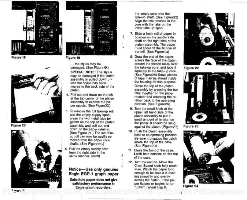
To turnthisfeature on, simply
pressthe2nd key, then press the
"4" key. Thepaperspeed will im-
mediately slowdown, signifying
thatthefunctionisenabled.
ToturntheAlternate Transmit
andPrintfeature off, simply press
the2ndkeyandthen press the
"7" key.Thepaperspeed will im-
mediately speed up, signifying that
thefunction hasbeen turned off.
When entering anynumber or
combination ofkeys on thekey-
boardandyoumakeamistake,
press the2nd KE'yç then 0.This
will clearthekeyboard. Forexam-
ple,ifyou wanted toset aLower
Limitof50feetandpressed
40
feet instead, beforepressing
the
LowerLimitKeypress 2nd -0
andthekeyboard will be cleared.
You couldthenpress5 -0-Lower
Limitforthedesired range.
Tocausethe Z-15 toreprint
the level ofDiscrimination, SCC,
or Pulse Width atthebottom of
thepage, simply press 2ndand
then thecorresponding key (DISC,
SCC/MARK, or PULSE) and itwill
bereprinted immediately.
EAGLE
PaperSaving Feature
Z-15
COMPUTERGRAPH
APPROXIMATE PAPER SPEED
Without Alternate Transmitand Print
INSTALLATION INSTRUCTIONS
LOWER
LIMIT
Minimum —
PaperSpeed Maximum
PaperSpeed
Inches Hours Inches Hours
RANGE
(feet)
10-120 PerMm Per Roll Per Mm Per Roll
1.0 10 2.35 4.25
130-510 0.5 20 1.4 7.14
520-830 0.15 66 0.75 13.3
Below 840 0.15 66 0.75 13.3
—
APPROXIMATE PAPER SPEED
With Alternate Transmitand Print
Minimum Maximum
LOWER
LIMIT PaperSpeed PaperSpeed
Inches Hours Inches Hours
RANGE (feet)
10-120 Per Mm Per Roll Per Mm Per Roll
0.5 20 1.4 7.14
130-510 0.20 50 0.8 12.5
520-830 0.15 66 0.75 13.3
Below840 0.15 66 0.75 13.3
- -: -
on I /
c.u_
,r-1
HoJw:
QJE1
ji
:1
LITHO USA 988-0104-01
1-800-331-2301
r P0.Box
669.GATOOSA,OK74015
AOlVISIONOFL.OWRANCEELSCTROMCS INOKLAHOMA (918) 266-5373
PDF compression, OCR, web-optimization with CVISION's PdfCompressor
Table of contents
Other Eagle Sonar manuals
Eagle
Eagle FishMark 500C User manual

Eagle
Eagle CUDA 240I S Operating manual

Eagle
Eagle FishEasy 350c Installation instructions

Eagle
Eagle CUDA 350 S/MAP User manual

Eagle
Eagle III User manual

Eagle
Eagle Magna User manual

Eagle
Eagle Cuda 300 Portable User manual

Eagle
Eagle Mach 1 User manual

Eagle
Eagle Ultra III User manual

Eagle
Eagle FishEasy 2T User manual

Eagle
Eagle Ultra II User manual

Eagle
Eagle UltraNav User manual

Eagle
Eagle 101 User manual

Eagle
Eagle Z-5000 User manual

Eagle
Eagle FishEasy 240 Portable User manual

Eagle
Eagle CUDA 242 - ADDITIONNAL User manual

Eagle
Eagle Six-Sixty User manual

Eagle
Eagle MagnaView User manual

Eagle
Eagle FishEasy 320C User manual

Eagle
Eagle FISHEASY ST - User manual