LCD-Liquidcrystaldisplay. Thescreen ordisplay ofaLiquidCrystal
Graph
sonarinstrument.
LCG-LiquidCrystal Graph.
NOISE-Anyundesired
signal. Electrical noise is causedby engine
ignitions systems, radios, etc. Acoustic noiseiscaused
by
thevibration
of theengineor other mechanical sources. Noise appears on the
display
as random dotsor lines.
OPERATING FREQUENCY-Frequency of a sonarunit'stransmitter
andreceiver. (SeekHz.)
OUTPUTPOWER
-Theamplitudeofelectrical energy
transmittedfrom
the sonar unit tothetransducer. Measured in watts, thehigherthe
outputpower,the
deeperasonarunitcanread, andmoredetailcanbe
displayed.
PIXEL
-Thesmalldotsorsquares
onaliquidcrystaldisplayorCAT.
PIXELDENSITY -Thenumber ofpixelsper square inch on a liquid
crystal display. Typically,thegreaternumber of vertical pixels, the
bettertheresolution.
PULSE LENGTh-Theamountoftimethatthesonartransmits.Thisis
measured in micro-seconds. Theshorterthe pulselength, thebetter
theresolution. For
example, a30
micro-secondpulse
length
isequal to
aoneinch resolution.
RANGE The section of water shown on the sonar display. For
example, a 60foot rangehas zerofortheupperlimit and 60 forthe
lowerlimit.
REMOTE-Anintelligent "repeater" unitthatreceivesdepthinformation
fromanothersonarunit. A remote doesn'thave a transmitteror re-
ceiver. However,
itdoeshaveit'sownfeaturesthatare adjustable and
operate separately
fromthemaster.
RESOLUTION -The abilityof a sonar unit to separatetargetsfrom
each otherorfromthebottom.
SCALE -The markings on a sonar unit'sdisplay. To determine the
depth ofa
target,simplycompare the
target's
location 10thelocationof
thescalemarkers onthedisplay.
INTRODUCTION
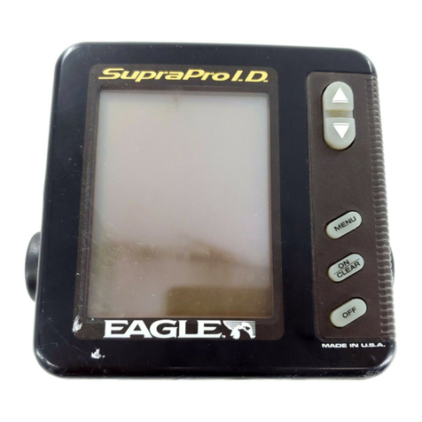
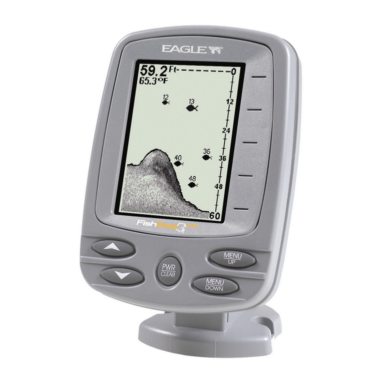
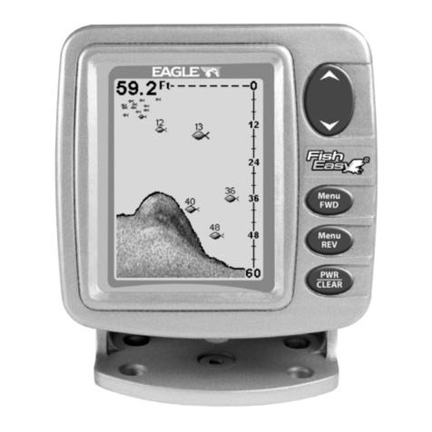
Welcome totheworldofsportfishing sonar. YourEagle Fishl.D. and
Fish 1.0. Plus arehighqualitysonar designed forboth professional and
novice users.These units have an automatic featurethat finds and
displays
thebottom
depth,
fish, and structure. Asyou becomefamiliar
with your Fish 1.0., you can "fine tune" the unit to thesurrounding
conditionstogetthemostfromyoursonar.
(Note: Alloperating
instructions fortheFish l.D. andFish 1.0. Plus are
the sameexcept
forspeedand temperature. OnlytheFish l.D. Plus
hasthosefunctions. Tosimplify
thismanual, allreferences totheFish
1.0.willalsoholdtruefortheFish1.0. Plus.
To get startedwith your Fish l.D., first readthe installation section.
Thisiswhereitallbegins, and improper installation cancause
problems
downtheroad. Afteryou'vereadtheseinstructions and installed your
Fish l.D., readthe rest ofthis manual in detail. The moreyou know
when
youget
tothewater, themore
yourFish 1.0.willdoforyou. Take
this manual forreference when
youheadforthewater.
INSTALLATION
Mounting
Install theunitin any convenient location, provided
thereisclearance
whentiltedforthebest
viewingangle. Holesin thebracketbaseallow
woodscrew or
through
boltmounting. Place apiece
ofplywood onthe
backofthinpanelsto secure themounting hardware. Makecertain
there is enough room behind the unit to attach the power and
transducercables.
You can routethepowerand transducer cables through
the one inch
holeinthebaseofthe
gimbal
bracket. Thenpassthem
through
ahole
inthe
mounting surface. Firstpass
thetransducerconnectorandcable
upthrough
thehole andgimbalbracket. Thenpushthepowercable
wire down
through
thebracketanddash. After routing thecables,fill
the holewith siliconerubber adhesive (RTV). Offsetthe bracketto
coverthemajoilty
ofthehole.
PowerConnections
TheFishl.D.operates
froma12voltbatterysystem. Attachthe
power
cable to an accessoryor power buss. If you have problemswith
electrical interference, then attach the cable directlyto the battery.
28 1
PDF compression, OCR, web-optimization with CVISION's PdfCompressor
