P139-HD Audio System User Manual
GA063-3 Rev G 08/25/2015 Page
of 35
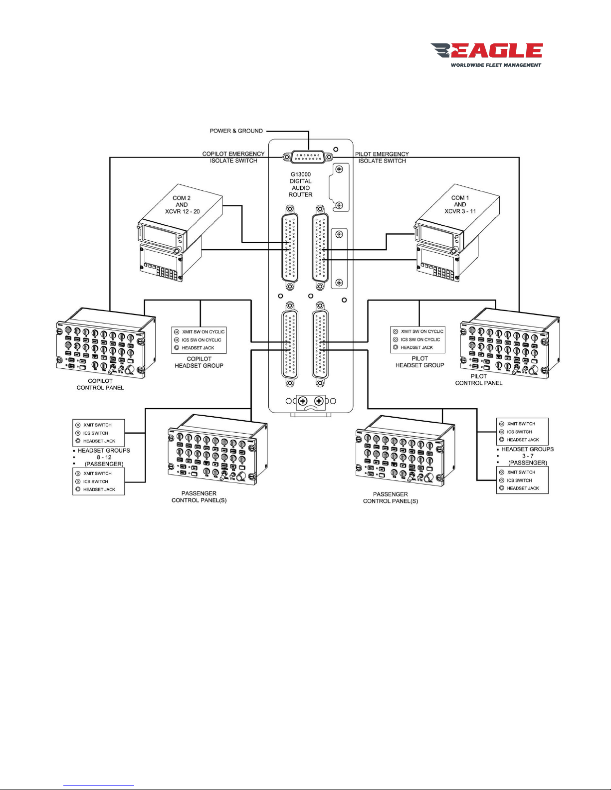
The P139-HD (D) and (S) Audio Systems consists of a G13000 Digital Audio Router, a number of control
panels (type and number of control panels depends on the customers’ configuration) and associated
cabling. The P139-HD (T) system uses the G13160 3-board audio router instead of the G13000 router.
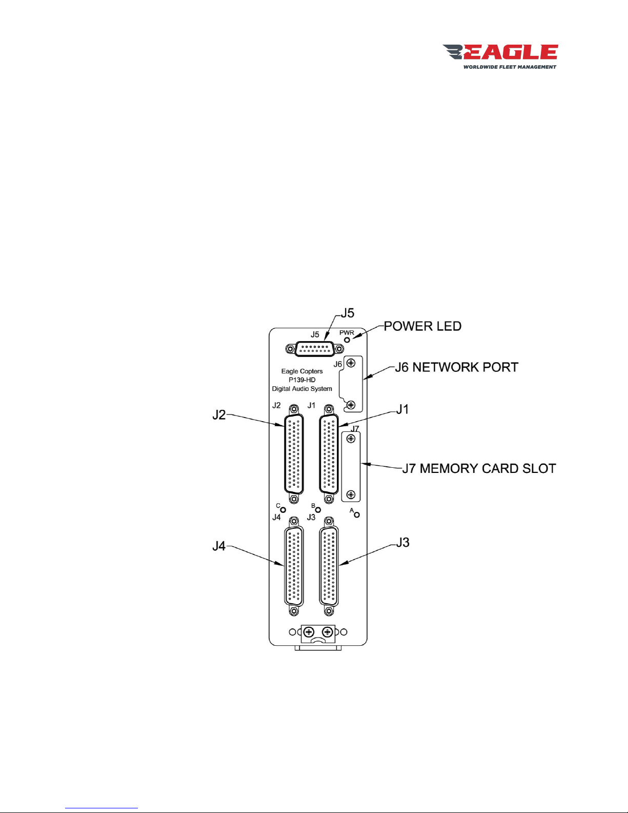
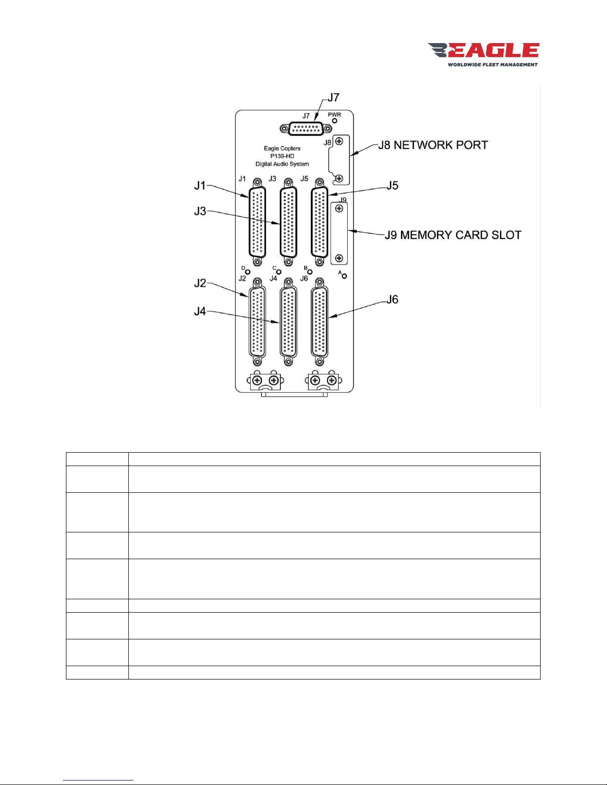
The G13000 front panel has seven connectors and four LEDs:
Radio Ports COM1 and XCVR3 –XCVR11. COM1 and XCVR11 have relays for the
Pilot Emergency Isolation Mode.
Radio Ports COM2 and XCVR12 –XCVR20. COM2 and XCVR20 have relays for the
Co-pilot Emergency Isolation Mode.
Pilot Headset and H/S3 –H/S7. Pilot Headset has relays for the Pilot Emergency
Isolation Mode and a dedicated COM1 Transmit Keyline.
Gnet Ports 1 and 2. Each port may connect to multiple control panels.
Co-pilot Headset and H/S3 –H/S7. Co-pilot Headset has relays for the Co-pilot
Emergency Isolation Mode and a dedicated COM1 Transmit Keyline.
Gnet Ports 3 and 4. Each port may connect to multiple control panels.
Power and Ground Connections. Individual control lines for Pilot Emergency Isolation
Mode and Co-pilot Emergency Isolation Mode. Two control panel Dimmer input lines.
Ethernet port for accessing the Configuration Web Page.
Slot for an MMC card containing the Configuration Web Page software and backups of
previously-saved configurations. The Audio system will function correctly without an
MMC card present, but the Configuration Web Page will not be available. NOTE: MMC
card MUST NOT be inserted or removed with the power on. MMC card should be
inserted with label facing towards J1.
Green when power is applied.
System Status LED. Flashes rapidly when system is operating correctly.
Status LEDs. May be green or red depending on system status. See Section 10.3
Table 1 P139-HD (D) Connectors
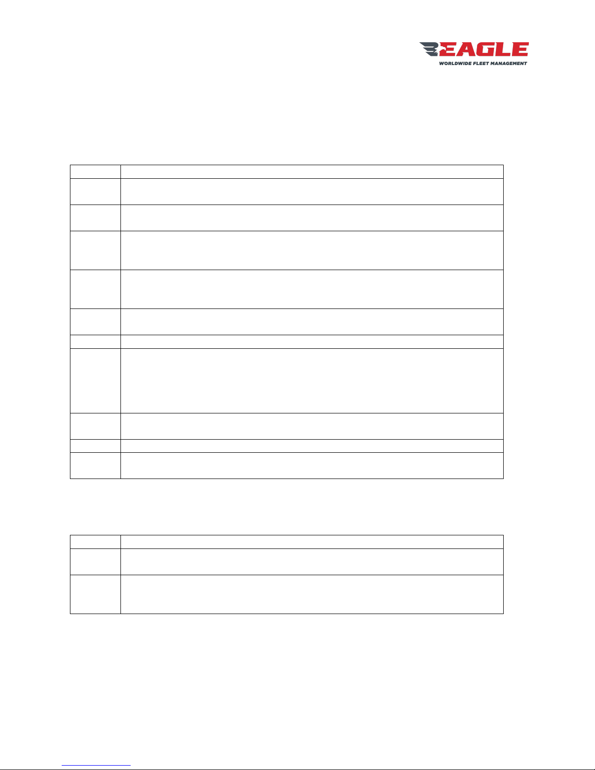
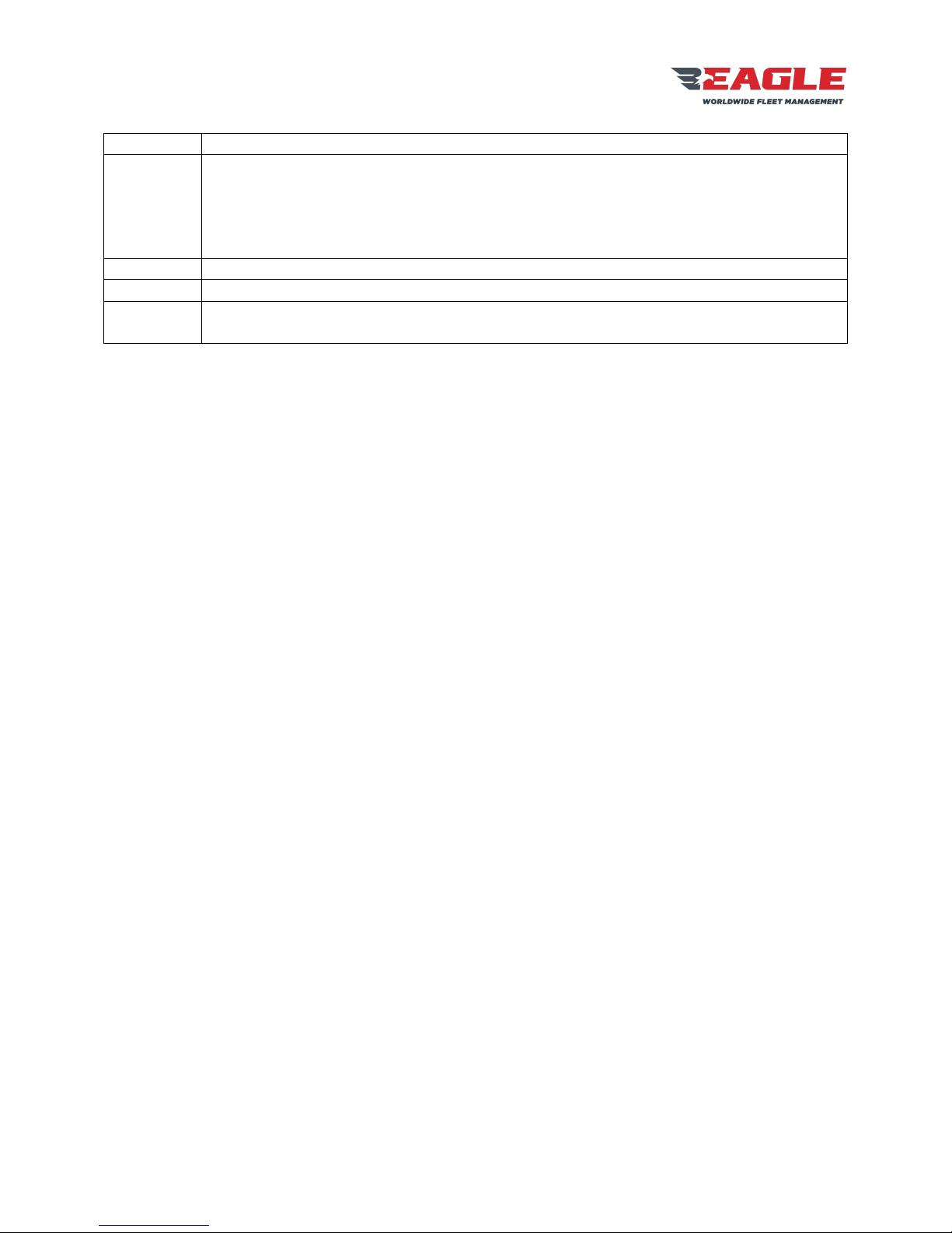
In a single board system J1 and J3 connectors and LED B are not installed and J2 and J4 have the
following functions:
Radio Ports COM1 and XCVR2 –XCVR10. COM1 and XCVR10 have relays for the
Pilot Emergency Isolation Mode.
Pilot Headset and H/S2 –H/S6. Pilot Headset has relays for the Pilot Emergency
Isolation Mode and a dedicated COM1 Transmit Keyline.
Gnet Ports 1 and 2. Each port may connect to multiple control panels.
Table 2 P139-HD (S) Connectors
Please see drawing G13004 for connector pinouts and cable descriptions. Not all installations will use all
ports, please see installation drawings for your system.