EAGO AM151ETL-L User manual

Installation Instruction of
AM151ETL-L
TS-series Control panel

01
02
03
04
05
07-11
12
13-14
Component Struction
Water and wire line instruction diagram
Connecting diagram of faucet pipe
Installation steps
Faucet's usage instruction
TS Control Panel
Troubleshooting
Maintenance Card
1. Please read carefully and follow all instructio ns w he n op er at in g.
2. Qualified earth leakage circuit-breaker mus t be i ns ta ll ed a nd
tested with trial jump to certify the device is qualified and sa fe ty
before using the product.
3. To avoid electrical shock, the replacing of the wire must be done
by the electrical engineer or the retailer. Customer co ul d no t
replace by yourself.
4. Ground wire of massage water pump and air pump must be
connected to ground well, the minimum size copper wi re o f gr ou nd
wire must not be less than 1.5mm².
5. It is forbid to remodel, add or take part products.
6. Please don't use this product after alcohol or drugs.
7. The children shall be closely supervised by parents to use product.
8. All the electrical spare parts except the remote control m us t be p ut
suitable and stable to avoid slip into the tub.
9. Warning: the mixed water temperature shall never exceed 60
degree centigrade.
10. Don’t use sulphuric acid, hydrochloric aci d, l ye a nd o th er m ix ed
strong corrosive chemical liquid to clean produc t.
11. The water pump would be very hot when running. Please don’t
touch the surface of the machine to avoid scald.
12. The water level must be higher than the jet before turning on the
product.
13. Please don’t drop anything in or insert water pu mp a nd t he
opening hole of machine.The socket position shou ld b e su it ab le .
14. Warning - To prevent risk of electric shock, please connect the
GFCI / RCD (earth leakage protection device) socket.
15. Warning - To prevent electric shock, please do not connect any
extension cord to the power supply.
16 Caution - please use the product under the follow in g co nd it io n:
water pressure is 0.15 ~ 0.40MPa, the ground must have the
ability to support the estimated load, water can not exceed the
overflow level, the washroom need to reserve enough sp ac e fo r
proper to handle the overflow of water.
17. WARNING - for bathtub to be used normally please do not grasp
the hand wheel drainer, nozzles, piping, hand ra il s, e tc ., to c au se
any leakage and other problem when unpacking t he p ro du ct .
Safety Information
Maintenance instruction
1. Clean the acrylic surface:
Clean acrylic surface with cotton flannel or sponge and water in daily life. If there
is scratch on the surface, please use No. 1500 water abrasive cloth polishing
slightly to clear away scratches, and then polish with toothpaste, cotton flannel.
Please don’t use strong caustic chemical liquid, such as sulphuric acid,
hydrochloric acid, lye during maintenance.
2. Plated item maintenance:
Clean the surface of plated item with cotton flannel, please don’t use coarse cloth.
3. Suction net cleaning:
Turn the screw out and take the suction net out to clean dirt, to keep the water
going through smoothly. Don’t use strong causticity chemical liquid to clean the
product, such as sulphuric, hydrochloric acid, lye and so on.

1
AM151ETL-L Component Struction
Installation Instruction 2
AM151 Water and wire line instruction diagram
17
21
22
23
24
31
30
29
28
27
26
25
20
19
18
16
13
15
14
12
11
10
9
8
7
6
5
4
3
2
1
No. Name No. Name
Three-piece faucet
PC board
Pillow
Bathtub
Ozone generator
Skirt panel light
Light installation panel
Lengthened plastic
Water pump
PC board power box
Bathtub leg
Stainless steel bracket
Junction box
Speaker
Heater
Back jet
Drain elbow
Deodorized drain
Bottom light
Drain
1 Inch three way
One way stuff
Fitting nut
4CM conversion
Suction
Side jet
½ Inch three way
Movable straight pipe
Drain valve
Hand shower holder
Hand shower

3Installation Steps 4
AM146/151/154/156/196
Hot
water
switch
Cold
water
switch

Shower head
Waterfall OFF ON
Jet
BA
5Faucet Switch Diagram 6
OFF ON OFF ON
Shower head
OFF
Jet
Two sets of the faucet:
A.The faucet is the function conversion.Turn 90° left is the
pipe cleaning function while 90° right is the shower head.
B.The cold-hot water inlet valve is both for hot and cold
water.The one with red label or with H mark is for hot
water,while the one with blue label or with C mark is for
cold water.You could adjust the label on the faucet to get
your wanted temperature.
Three sets of the faucet:
A.Function conversion value.Turn 90° left is the pipe
cleaning function while 90° right is the shower head.
B.The water-in pipe where with blue label is cold water,
and the hand-hole faucet with label C is also cold
water.Turning left could alternate the volume of the
cold water.The maximum is 90° to the left.
C.The water-in pipe where with red label is hot water,
and the hand-hold faucet with label H is also hot water.
Turning left could alternate volume of the hot water.
The maximum is 90° to the left.
The product designs for water going in from nozzle,also could be used to adjust shower head water in or water in from
water outlet faucet.Water in from shower head is usually for body,head cleaning or etc.places.

7TS Control Panel 8
TS Control panel instruction
Capaci tiv e water lev el se nsor
Light (c olo r is change a uto matical ly)
Speake r
Radio an ten na
Wate r tempera tur e probe
Contro l pan el
Only can b e mat ched the
DC12V oz one gener ato r
250 Crim p ter minal
Thermo sta tic power
Main pow er Wate r pump powe r
Electric parameter
Spare part
Parameter
Rate voltage
Rate voltage
Rate power
Massage
pump
Ozone
generator
Bottom
light Thermostatic Control panel Speaker Note
Electromagnetism
valve
TS Wiring Diagram

9TS Control Panel 10
6. “
” Jet
Touch “ ” to turn on the jet, one admission valve works, touch “ ” for the first time, two admission valves work; touch
“ ” for the second time, three admission valves work; touch “ ” for the third time, four admission valves work; touch “ ” for
7.
the fourth time, four admission valves turn off; So the cycle to repeat.
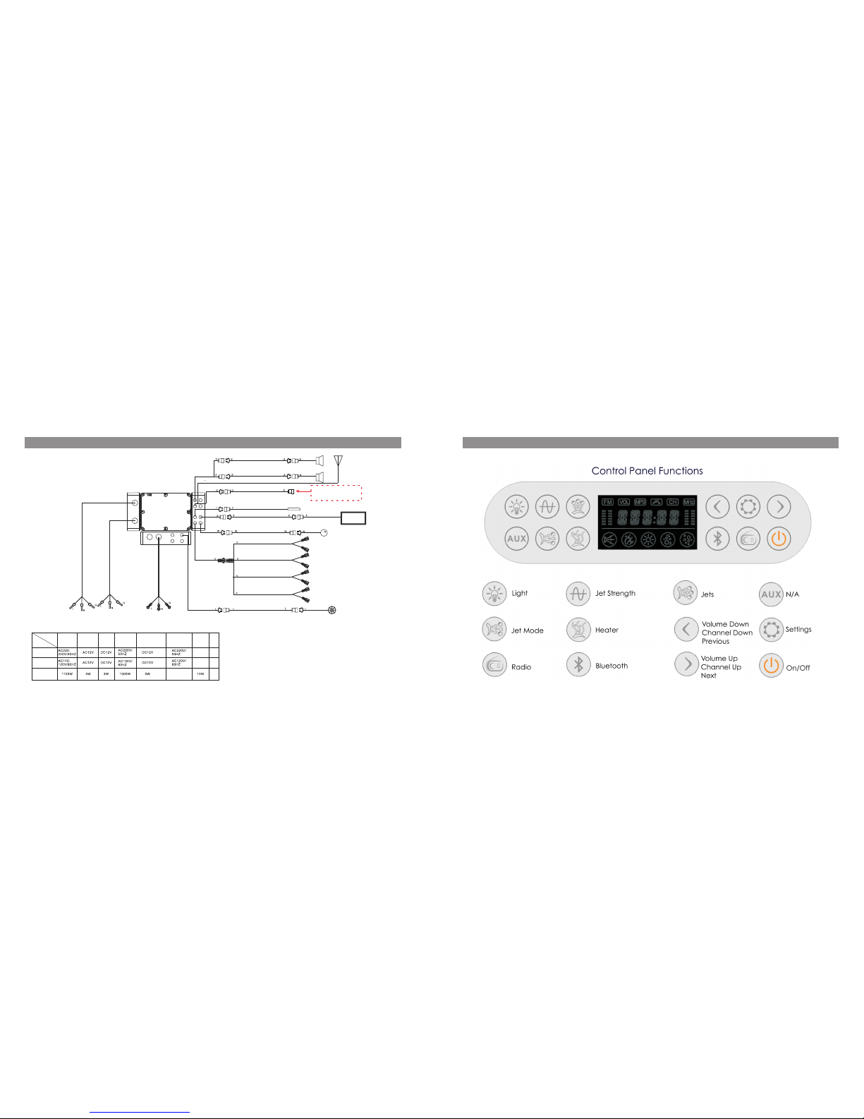
” Jet Strength
Touch “
” to turn on the jet strength, one admission valve works, touch “ ” for the first time, air inlet circular with 3 seconds
interval. The order is: one admission valve, two admission valves, three admission valves, four admission valves, three admission valves,
two admission valves, one admission valve. Touch “ ” for the second time, four admission valves work for 2 seconds, and turn off for 1
second. So the cycle to repeat. Touch “ ” for the third time, four admission valves turn off. So the cycle to repeat.
8. “ ” Radio
8.1 Touch the “ ” to turn on the radio when the control system is turn on, the LCD shows the current frequency and “ ” “ ”
icon; touch the “ ” again to turn on the radio, the current frequency and “ ” “ ” icon shows on LCD disappear.
8.2 FM broadcast receiving frequency range is 87.5MHz---108.0MHz.
8.3 Frequency increase
Touch “ ” to increase a step length (1 step length = 50KHz) tuned frequency when the radio turns on. Touch this key for more than
2 seconds, the system would search FM program upwards, digital lock would lock the program automatically, LCD shows the corresponsive
frequency; when it reaches upper limit 108.0MHz and touch this key, the frequency will turn to 87.5MHz.
8.4 Frequency decrease
Touch “ ” to decrease a step length (1 step length = 50KHz) tuned frequency when the radio turns on. Touch this key for more than
2 seconds, the system would search FM program downwards, digital lock would lock the program automatically, LCD shows the corresponsive
frequency; when it reaches lower limit 87.5MHz and touch this key, the frequency will turn to 108.0MHz.
8.5 Volume adjustment
Touch “ ” when radio turns on, LCD flicker “VOL” and number means the volume can be adjusted. Touch “ ” to increase the
volume, touch “ ” to decrease volume. The volume range is 0-20.
8.6 Channel saving/channel picking out
” the LCD flicker “CH” icon, touch “8.6.1 Channel saving: select the channel need to save when the radio turns on, touch “ ”
” to choose the saving position, the channel can be saved in this position when touch “or “ ” for 2 seconds again.
The characteristics of the control system electrical box
1) AC220V-240V/ A C11 0V-120V Rated voltage: 2)Rated frequency: 50HZ/60HZ 3)Standby Power: <10W (All load is closed)
4)Ambient temperature: + 5℃~ +40℃
Devices being controlled by control system
1) 2HP 2)1500W 3) DC12V/1W
5)Ozone generator: D C 1 2 V /6W 6)Speaker: 8Ω/15W(Maximum)
Surfing water pump: Heater: Bottom light:
4)Electromagnetism valve: 4*DC12V/5W
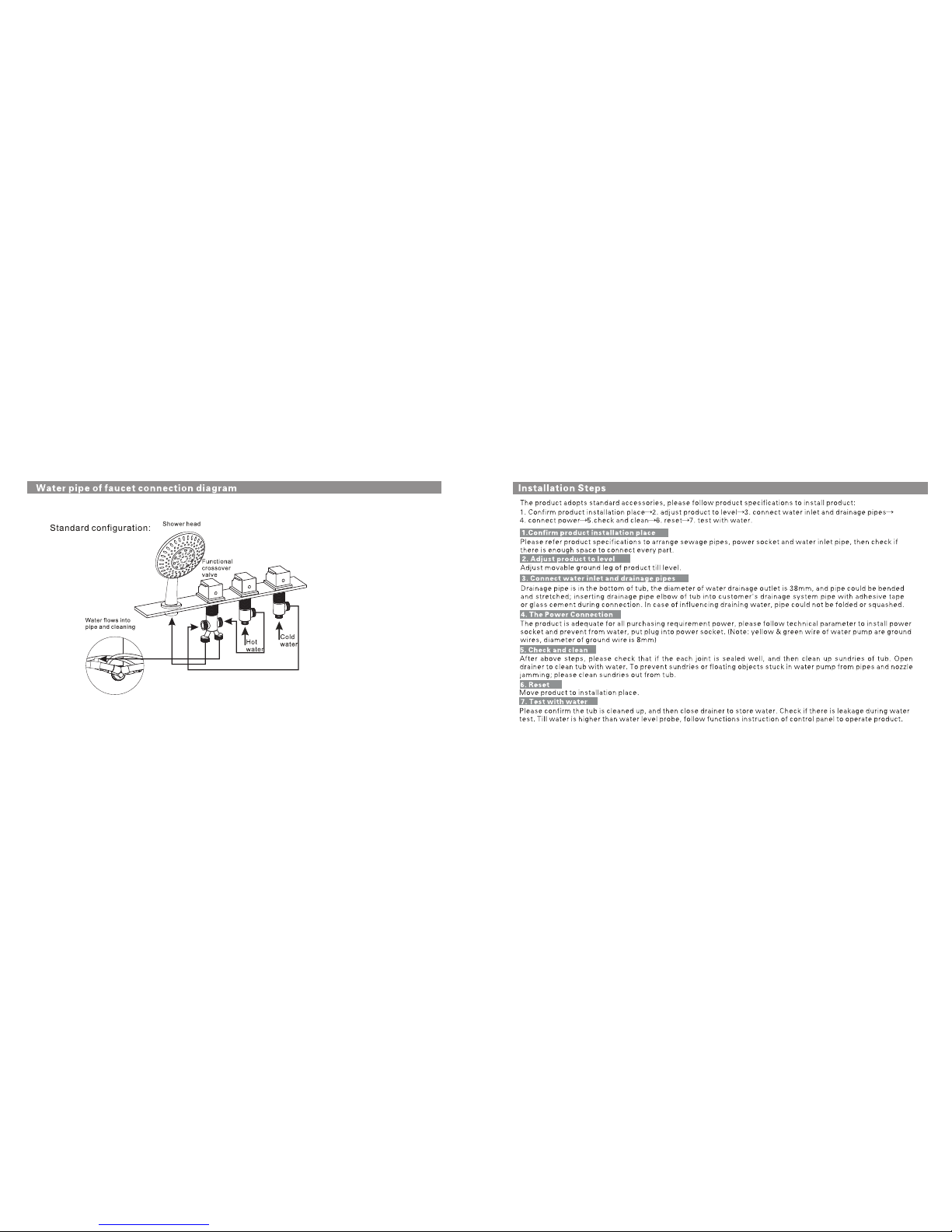
Control panel operation instruction
1.Press any key a buzzer would let out.
2. “ ” On/Off
2.1 The control system starts operation when touch this key, the bottom lights would turn on at the same time.; press this key again to turn off the control system.
2.2 The control system would turn off automatically when it turn on 60 minutes later, and all the load would turn off.
3. Child lock
The control system would lock all keys automatically when you do not use the control panel in 5 minutes. The LCD shows “LOCK” icon. To unlock the
control panel by pressing any key, the “LOCK” icon disappear.
4. “ ” light
Each time to touch “ ” the lights would change to another color, the LCD shows a light icon when the control system turns on; the lights colors
would change circularly when touch “ ” for the seventh times; the lights would turn off when touch “ ” for the eighth times.
5. “
” Jet Mode
5.1 There is water level sensor in the control system to prevent water pump from running idle to damage water pump under less water or without water.
5.2 The jet function would turn on when touch “
the water level is below the set value, the “
”, the LCD shows “ ” icon. The water pump would not work when the water level sensor test
” icon twinkle. The water pump would start to work when the water level sensor test the water level reaches
to the set value, the “ ” shows dynamic.
5.3 Touch “
” to turn off the water pump when the jet function is turn on, and the jet mode icon would disappear. Also the heater would turn
off (if the heater is turn on).
TS Control panel instructionTS Control panel instruction

11 Troubleshooting 12
TS Control panel instruction
8.6.2 Channel picking out: touch “ ” when the radio turns on, the LCD shows the corresponsive channel and “CH” icon, touch
“ ” or “ ” to pick out the corresponsive channel.
9. Bluetooth
9.1 When the control system turns on and the radio turns off, touch “ ” for 2 seconds to disconnect the corresponsive device and search the new
device again.
9.2 When the control system turns on and touch “ ” to turn on the bluetooth music playing function, LCD shows “BT---C”; touch “ ”
again to turn off the bluetooth music playing function, “BT---C” disappear.
9.3 If the bluetooth pairing failed, LCD flicker shows “BT--C”; if succeed, LCD constant shows “BT--C”.
9.4 When the bluetooth music playing function turns on, touch “ ” or “ ” to choose previous or next music.
9.5 When the bluetooth music playing function turns on, touch “ ” to play or pause music.
9.6 Touch “ ” bluetooth music playing function turns on, LCD flicker “VOL” and number means the volume can be adjusted. Touch “ ”
or “ ” to adjust volume.
10. Heater
10.1 The heater can not be turned on until the surfing water pump turns on.
10.2 Touch “ ” to turn on the heater function, LCD constant shows “ ” icon. The heater would start or stop to work according to the
o
temperature inside the bathtub and the setting temperature (acquiescent temperature is 37 C).
10.3 Touch “ ” again to turn off the heater.
10.4 Temperature setting
0
10.4.1 Turn on the heater and touch “ ”, LCD flicker shows temperature and “ C”, touch “ ” or “ ” to set the temperature. The
0
LCD shows the correponsive temperature. Each time to touch “ ” the temperature would raise 1 C; each time to touch “ ”
0
the temperature would drop 1 C; the temperature would disappear when you do not touch these two keys 5 seconds later.
o o
10.4.2 Temperature range: 30 C--45 C.
11. Ozone
Touch “ ” to turn on the ozone. It would turn off automatically when it works for 10 minutes; touch “ ” to turn off the ozone manually.

13 Maintenance Record 14
Table of contents
Other EAGO Hot Tub manuals
Popular Hot Tub manuals by other brands

Penner Bathing Spas
Penner Bathing Spas Dream Spa 760010-1 Installation & assembly instructions

Riptide
Riptide Starlight Corona owner's manual

AQUA SPA
AQUA SPA Heaven user manual

Jacuzzi
Jacuzzi SWIMSPA Power Pro J19 manual

Maestro
Maestro PEDICURE SPA owner's manual

Coast Spas
Coast Spas COAST FRESHE owner's manual

Jacuzzi
Jacuzzi alimia Instructions for installation

Blue Whale Spa
Blue Whale Spa Balboa MVP260 instruction manual

Teuco
Teuco 611 Use and maintenance manual

Spas
Spas Smart S-2 owner's manual

Dimension One Spas
Dimension One Spas Wayfarer Specifications

Premium Leisure
Premium Leisure Leisure Edge LE852 owner's manual