manuals.online logo
Brands
  1. Home
  2. •
  3. Brands
  4. •
  5. E&I
  6. •
  7. Amplifier
  8. •
  9. E&I 1140LA User manual

E&I 1140LA User manual

The material contained in this document is the property of Electronics & Innovation Ltd., it is subject to
change without notice.
August 2012 Revision F
1
1140LA
Broadband Power Amplifier
HIGH RF VOLTAGES MAY BE PRESENT AT THE OUTPUT OF THIS UNIT. All
operating personnel should use extreme caution in handling these voltages and be
thoroughly familiar with this manual.
Do not attempt to operate this unit prior to reading this manual.
The material contained in this document is the property of Electronics & Innovation Ltd., it is subject to
change without notice.
August 2012 Revision F
2
Warranty
Electronics & Innovation Ltd., (hereafter E&I) warrants for the period of three years from
the date of original delivery, each unit to be free of defects in materials and workmanship.
For the period of 36 months E&I will, at its option, repair or replace defective parts so as
to render the unit fully operational such that it performs according to the original
specifications; free of charge to the original purchaser.
Should warranty service be required, the unit must be returned to E&I, freight cost to be
borne by the owner. If, in our opinion, the unit has been damaged by use outside the
limits prescribed in this manual or by accident, then the warranty shall not be honored. In
such a case E&I will provide an estimate for repair, assuming repair is possible and
provide a quote at standard service rates.
Contents
Chapter 1
General Information……………………………………………………………3
Chapter 2
Operation………………………………………………………………………..4
Chapter 3
Technical Information………………………………………………………….7
Chapter 4
Maintenance……………………………………………………………………8
Chapter 5
Safety……………………………………………………………………………12
The material contained in this document is the property of Electronics & Innovation Ltd., it is subject to
change without notice.
August 2012 Revision F
3
Chapter 1 Introduction
The 1140LA is a broadband solid state amplifier covering the frequency spectrum from 10
KHz to 2 MHz. It is rated at 1000 watts of RF power with low harmonic and
intermodulation distortion. Over 1500 watts of saturated power can be produced with
increased distortion products from 100 KHz to 2 MHz. A quasi linear Class AB design, the
1140LA will amplify inputs of AM, FM, SSB, pulse and any complex modulation signals.
The amplifier has 55 dB gain, it is unconditionally stable and will not oscillate even with
combinations of mismatched source and load impedance. It is protected against failure
due to output load mismatch and/or overdrive.
RMS forward and reverse powers are monitored by a front panel meter. An integral power
supply permits operation from 120/240 single phase AC power.
1.2 INSTRUMENTATION IDENTIFICATION
Each amplifier is identified by a serial number tag on the back panel of the unit. Both the
model number and the serial number should be quoted to identify specific unit.
1.3 SPECIFICATIONS
Physical and electrical specifications are listed in Table 1-1 below
The material contained in this document is the property of Electronics & Innovation Ltd., it is
subject to change without notice.
August 2012 4 Revision F
Table 1-1. SPECIFICATIONS
FREQUENCY COVERAGE:
10 kHz to 2 MHz
GAIN:
55 dB min, ±1.5 variation
CLASS A LINEAR OUTPUT:
1000 Watts
SATURATED RF POWER OUTPUT:
1100W Min. from 10 kHz –100 KHz;
1500W Min. from 100 KHz –2 MHz
INPUT IMPEDANCE
50 ohms, VSWR, 1.5:1 Maximum
OUTPUT IMPEDANCE:
50 ohms, VSWR, 2:1 Maximum
STs STABILITY:
Continuous operation into any load or
source impedance
PROTECTION:
Unit will withstand a + 13dBm input
signal (1.0 Volts RMS) for all output load
conditions, without damage
POWER OUTPUT METER:
RMS power detection. ± 3% of full scale
accuracy, 100 KHz - 1 MHz. 10-100 KHz
see table below. Above 1 MHz ± 5%
POWER REQUIREMENTS:
100 –240 VAC 47-63 Hz.
SIZE:
13.12” x 16.71” x 20.1”
333.2 x 424.4 x 510.1 mm
WEIGHT:
108 lbs (49 kg)
CONNECTORS:
N
OPERATING TEMPERATURE:
0 –40 C
RACK MOUNTING:
For frequencies below 100 KHz see table below for error correction factors. To
obtain accurate RMS power number increase the front panel reading by the
percentage corresponding to the frequency of use as seen below.
Frequency Corretion factor
MHz %
0.01 13.0%
0.02 8.0%
0.03 5.8%
0.04 4.8%
0.05 4.5%
0.06 3.5%
0.07 3.0%
0.08 2.5%
0.09 2.8%
0.1 2.5%
The material contained in this document is the property of Electronics & Innovation Ltd., it is
subject to change without notice.
August 2012 5 Revision F
Chapter 2 Operation
2.1 INTRODUCTION
The 1140LA RF amplifier is used to amplify the RF level of signal sources in the
10 KHz to 2 MHz range. No tuning or any other form of adjustment is required.
The 1140LA produces rated power output at its output connector, regardless of
load impedance. Any power reflected due to output load mismatch is absorbed in
the amplifier. Therefore, although the output impedance is 50 ohms (maximum
VSWR: 2:1), the amplifier will work into any load impedance.
2.2 RACK INSTALLATION
This unit is 7.4U high, 16.75” width. With the handles removed it will fit into a
standard rack.
2.2.1 Mains Voltage
The unit accommodates AC line voltages from 100 TO 240 VAC 47 –63 Hz.
2.3 OPERATION
A fixed line cord is supplied to form a connection between the mains supply and
the rear of the unit. This is configured from the factory with a 30A/250V plug.
Plug this into the AC mains outlet. The product ships with a standard plug. This is
an Interpower PN# is 88030310. www.interpower.com
2.3.1 Proceed as follows:
(i) Ensure that there is at least 3” or 7.5 cm clearance at the rear of the
unit for air flow.
(ii) Ensure RF input voltage is not excessive
a. The 1 V rms indicated maximum input voltage is 5 times the level of
the input signal required to achieve maximum output. Input voltages
in excess of 2 volts peak may permanently damage the instrument.
(iii) Connect the output via a 50 ohm coaxial lead and N plug to the load.
(iv) Connect the input signal via a 50 ohm coaxial lead and N plug to the
input connector.
The material contained in this document is the property of Electronics & Innovation Ltd., it is
subject to change without notice.
August 2012 6 Revision F
2.3.2 Front Panel Display
The 1140LA front panel has a passive LCD display designed for simplicity and
ease of use. During initialization, the LCD shows the software revision. After the
amplifier is initialized, the LCD indicates Forward Power, Reflected Power, and
amplifier status (see figure 2.1).
Pf:___W Pr:___W
Status:________
Figure 2.1 : Front Panel Display
Where Pf refers to forward power, Pr refers to reverse power, and Status
indicates “OK” unless there is a fault condition, such as:
Overheat (heat-sink temperature is too high for reliable operation)
PSU fault (internal fault in the main switching power supply)
In the event of a fault, the unit may be reset by cycling the power. In the case
over an over temp fault, ensure that the air inlet and out let are not restricted. If
the fault persists, please contact Field Service.
2.3.3 RS 232 Interface
The 1140LA features a standard RS-232 serial interface suitable for connection
to a PC or host system. The communication protocol is extremely simple to
facilitate readback and control with readily available terminal programs such as
Hyperterm. The RS-232 link has the following parameters:
Baud rate: 19200
Data bits: 8
Parity: none
Stop bits: 1
Flow control: none
An example configuration using HyperTerminal on a PC is shown in figure 2.2.
The material contained in this document is the property of Electronics & Innovation Ltd., it is
subject to change without notice.
August 2012 7 Revision F
In the default state, the RS-232 port will echo the same information sent to the
front panel LCD display, allowing a running datalog to be stored to disk using the
capture feature of the terminal program.
Single character commands can be sent to the amplifier to achieve the following:
"1" key enables telemetry (readback similar to LCD display) - this is the default
mode at power up
“2” key clears any faults and tries to start the supply.
“0” key disables telemetry (Complement to “1” key)
Custom commands and display lists can be implemented upon customer
request.
Figure 2.2: Example RS-232 setup using Hyper Terminal
The material contained in this document is the property of Electronics & Innovation Ltd., it is
subject to change without notice.
August 2012 8 Revision F
Chapter 3 Technical Description
3.1 GENERAL DESCRIPTION
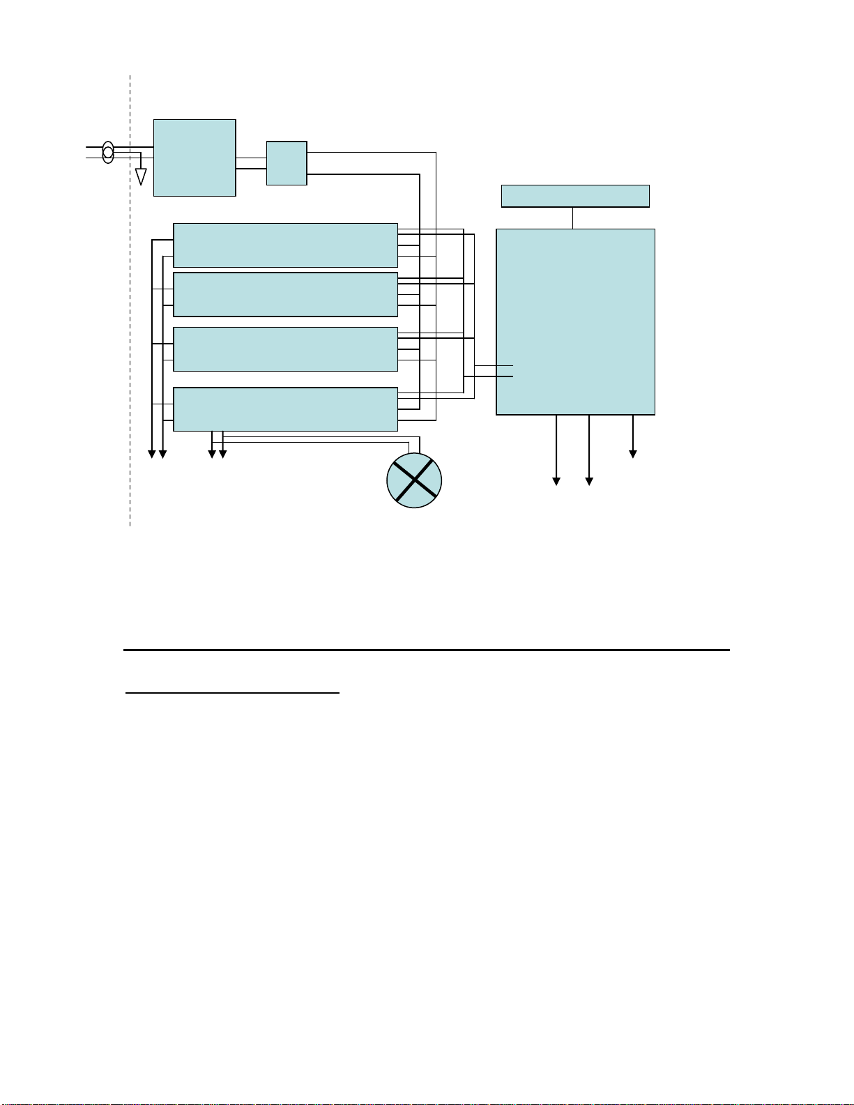
The 1140LA is designed to amplify signals by 55 dB in the frequency band of 10
KHz to 2 MHz. The signal from the front panel N connector is fed via a length of
50 ohm coaxial cable into the input of the splitter module. The signal from the
output of the splitter is coupled to the input drivers 1) & 2) the first stage of each
is the MMIC front end. The output signal of the MMIC is coupled to the gate of
transistor Q1. The further amplified signal appearing at the drain of Q1 is coupled
to the input of Q2. This is transformed to 50 and fed to the driver output BNC
port.
The driver output signal are fed through a length of coaxial cable to the input of
two power splitters, the four outputs of this are each fed to the four amplifier
modules. In each PA module the signal is split into two equal phase and
amplitude signals. These signals are fed to the inputs of transistors Q1 and Q2.
The amplified signals appearing at the drains of Q1 and Q2 are then fed to the
output BNC port via the impedance matching network. The output of the modules
is then fed to the combiner to produce a single signal.
The power signal is then fed into a length of 50 ohm coaxial cable to the RF bi-
directional coupler. The output of the coupler is then fed directly to the N
connector on the front panel, this is the unit output.
The forward and reverse coupled ports of the bi-directional coupler are fed to the
RF detector which is situated on the main control board. The RF detector feeds a
voltage, which is representative of the true RMS power to the control board
proper. The control board in turn drives the front panel display.
There are four switch mode power supply units three provide a 48 VDC 24
ampere source. The other provides 48VDC and 24 VDC outputs and provides a
total of 24 amps. The main power supply also has a 5 VDC output which feeds
the control board.
The material contained in this document is the property of Electronics & Innovation Ltd., it is
subject to change without notice.
August 2012 9 Revision F
Combiner
Splitter
Driver 1
2100L PA
Coupler
24 Volt
To Page 2 a
RF IN
RF OUT
To Page 2 b
To Page 2 c
To Page 2 b
48 Volt
48 Volt
RF Detect
2100L PA
2100L PA
2100L PA
Driver 1
Splitter
1140LA RF Amplifier
1140LA –SCH-01
The material contained in this document is the property of Electronics & Innovation Ltd., it is
subject to change without notice.
August 2012 10 Revision F
Chapter 4 Maintenance
4.1 INTRODUCTION
The E&I 1140LA RF amplifier requires no periodic maintenance. The instrument
is unconditionally stable and is fail-safe under all load conditions. Damage can
only be externally caused by the incorrect selection of the AC supply voltage or
by an input signal in excess of the specified 1 volt rms equivalent to a power level
of 13dBm.
This chapter therefore, deals only with certain fundamental procedures for fault
location.
AC IN
SMPS 48 Volt
SMPS 48 Volt
SMPS 48 Volt
SMPS 48 /24 Volt
To page 1 a
24 Volt
To page 1 b
Controller
To page 1 c
TTL Control
Front Panel LCD
To Rear
Panel RS232
Fans
CKT
BRK
Line
Filter
The material contained in this document is the property of Electronics & Innovation Ltd., it is
subject to change without notice.
August 2012 11 Revision F
Performance limits quoted are for guidance only and should not be taken for
guaranteed performance specifications unless they are also quoted in the
Specification Section 1.2.
4.2 PERFORMANCE CHECKS
To determine the amplifier’s performance carry out the following procedure.
4.2.1 Initial Check
The following check can be made after repair and adjustments or
whenever the condition of the unit is in question.
a. Connect AC power supply. Switch on power and observe that the
display initializes.
b. Connect a sweep generator (HP 8601 or similar) capable of sweeping
the frequency range 9 KHz to 2 MHz, to the input connector.
c. Adjust the output level of the sweep generator so that a 50 ohm video
detector connected at the output of the unit will not be damaged by
excessive power output. (Reference section 4.4.1 for set up.)
d. Observe the gain versus frequency ripple on an oscilloscope calibrated
in decibels. The gain variation must be not more than +/- 1.5 dB over
the frequency range.
e. Connect a calorimetric power meter (HP435B or equivalent) through a
30 dB 500 watt attenuator to the output connector. Adjust the input CW
signal to any frequency between 9 kHz and 2 MHz for 1000 watts
output.
f. Observe the harmonic distortion of the output, properly attenuated, on
a spectrum analyzer. The harmonic components contributed by the
amplifier should be better than 10 dB down from the fundamental.
The material contained in this document is the property of Electronics & Innovation Ltd., it is
subject to change without notice.
August 2012 12 Revision F
4.3.1 Measurement of Gain
1. Equipment Required (or equivalent):
a) Osilloscope - Tektronix T921
b) Sweep/Generator - HP8601A
c) Signal Generator - Exact Model 7060
d) 50 ohm Detector - Wavetek D151
e) Attenuator, 30 dB, 5000 Watts Bird
Figure 4-1. Gain Measurement
2. Connect the equipment as shown in Figure 4-1, then proceed as follows:
a) Set the oscilloscope to DC, Time/cm to Ext. X, and gain to
l0mv/cm.
b) Set the sweep generator to the video sweep mode with the start
frequency at 9 kHz and the sweep width to 2 MHz.
c) Disconnect the 1140LA from the set-up and connect the
sweep/generator RF output directly to the 50 dB attenuator.
50 dB Attenuator
RF Detector
Sweep Generator
RF Output
Sweep
Signal
Trigger
10 KHz –2 MHz
Input
The material contained in this document is the property of Electronics & Innovation Ltd., it is
subject to change without notice.
August 2012 13 Revision F
d) Adjust the output level of the sweep/generator for full vertical
deflection on the oscilloscope face.
e) Calibrate the scope face to show 3 dB in 1 dB steps by
attenuating the sweep/generator in 1 dB.
f) Return sweep/generator output level to full deflection. Rotate the
step attenuator (CCW) so that the output is reduced by 50 dB.
g) Reconnect the 1140LA into the test set-up of Figure 4-1.
h) Place the 1140LA power switch to the "ON" position.
i) Observe the gain versus frequency sweep on the oscilloscope.
The average gain should be greater 55 dB
The gain variation should be within the 3 dB as shown on the
oscilloscope.
4.4.2 Measurement of Harmonics
Figure 4-2.
1.) Equipment Required:
a) Sweep/Signal Generator
b) Calorimetric Power Meter HP435B
50 dB Attenuator
Sweep Generator
RF Output
10 KHz –2 MHz
Spectrum
Analyzer
Power Meter
30 dB
coupler
The material contained in this document is the property of Electronics & Innovation Ltd., it is
subject to change without notice.
August 2012 14 Revision F
c) Spectrum Analyzer.
d) Attenuator (30dB)
e) Coupler (30 dB)
2.) Connect the Equipment as shown in Figure 4-2, then proceed as follows:
a) Adjust the signal generator to a CW center frequency of 9 kHz, for an
indicated output of 1000 watts on the power meter.
b) Using the spectrum analyzer, check that the level of the carrier
harmonics is less than -25 dB with respect to the carrier while manually
scanning the frequency band of 10 KHz to 2 MHz. An indicated power
output of 1000W should be maintained during this operation.
4.5 PACKAGING FOR RESHIPMENT
In the event of the equipment being returned for servicing it should be packed in
the original shipping carton and packing material. If this is not available, wrap the
instrument in heavy paper or plastic and place in a rigid outer box of wood,
fiberboard or very strong corrugated cardboard. Use ample soft packing to
prevent movement. Provide additional support for projecting parts to relieve
these of unnecessary shock. Close the carton securely and seal with durable
tape. Mark the shipping container FRAGILE to ensure careful handling.
Chapter 5 Safety:
Do not attempt to operate this unit with the cover removed. High AC and DC
voltages are present. The cover protects against electrical shock due to AC line
voltages, high DC and RF fields. Further the cover provides part of the cooling
system design. Components, specifically on the RF driver board are prone to
over-heat and eventual failure if the unit is operated without the cover in place.
Ensure that the load is connected to the output prior to connecting the RF input
to the unit. This will prevent high voltages being present and exposed at the
output connector.
Only use the AC cord provided or equivalent.
Ensure that the mains outlet is properly grounded.

Other E&I Amplifier manuals

E&I 210L User manual

E&I

E&I 210L User manual

E&I 1040L User manual

E&I

E&I 1040L User manual

E&I 3100LA User manual

E&I

E&I 3100LA User manual

E&I 2200L User manual

E&I

E&I 2200L User manual

E&I 325LA User manual

E&I

E&I 325LA User manual

E&I 3100L User manual

E&I

E&I 3100L User manual

E&I 240L User manual

E&I

E&I 240L User manual

E&I 2400L User manual

E&I

E&I 2400L User manual

E&I 350L User manual

E&I

E&I 350L User manual

E&I A 1000 User manual

E&I

E&I A 1000 User manual

E&I 1000S04 User manual

E&I

E&I 1000S04 User manual

E&I 2500L User manual

E&I

E&I 2500L User manual

E&I 1020L User manual

E&I

E&I 1020L User manual

E&I 2100L User manual

E&I

E&I 2100L User manual

E&I A150 User manual

E&I

E&I A150 User manual

Popular Amplifier manuals by other brands

Fosi Audio BT20A PRO user manual

Fosi Audio

Fosi Audio BT20A PRO user manual

Plinius SA-REFERENCE instruction manual

Plinius

Plinius SA-REFERENCE instruction manual

McIntosh C32 owner's manual

McIntosh

McIntosh C32 owner's manual

RCS AUDIO-SYSTEMS MMA-400 Series operating instructions

RCS AUDIO-SYSTEMS

RCS AUDIO-SYSTEMS MMA-400 Series operating instructions

Audio Research SP-5 instruction manual

Audio Research

Audio Research SP-5 instruction manual

Denon PMA-A110 quick start guide

Denon

Denon PMA-A110 quick start guide

Taga Harmony HTA-1000B instruction manual

Taga Harmony

Taga Harmony HTA-1000B instruction manual

Fbt symbol 12000 user manual

Fbt

Fbt symbol 12000 user manual

Audio Research LS25 owner's manual

Audio Research

Audio Research LS25 owner's manual

SMART Audio 400 user guide

SMART

SMART Audio 400 user guide

Atlas PA702 owner's manual

Atlas

Atlas PA702 owner's manual

NAD 3400 Specification sheet

NAD

NAD 3400 Specification sheet

Denon HEOS Amp quick start guide

Denon

Denon HEOS Amp quick start guide

AUDAC AMP22 user manual

AUDAC

AUDAC AMP22 user manual

powersoft DigiMod 1000 quick guide

powersoft

powersoft DigiMod 1000 quick guide

Fredenstein ramDI operating manual

Fredenstein

Fredenstein ramDI operating manual

Krell Industries Evolution 202 Owner's reference

Krell Industries

Krell Industries Evolution 202 Owner's reference

Rotel RA-972 owner's manual

Rotel

Rotel RA-972 owner's manual

manuals.online logo
manuals.online logoBrands
  • About & Mission
  • Contact us
  • Privacy Policy
  • Terms and Conditions

Copyright 2025 Manuals.Online. All Rights Reserved.