manuals.online logo
Brands
  1. Home
  2. •
  3. Brands
  4. •
  5. E&I
  6. •
  7. Amplifier
  8. •
  9. E&I 325LA User manual

E&I 325LA User manual

Form 080/01
Complimentary Reference Material
This PDF has been made available as a complimentary service for you to assist in
evaluating this model for your testing requirements.
T G offers a wide range of test equipment solutions, from renting short to long
term, buying refurbished and purchasing new. Financing options, such as
Financial Rental, and Leasing are also available on application.
T G will assist if you are unsure whether this model will suit your requirements.
Call T G if you need to organise repair and/or calibrate your unit.
If you click on the “Click-to-Call” logo below, you can all us for FREE!
TMG Corporate Website TMG Products Website
Disclaimer:
All trademarks appearing within this PDF are trademarks of their respective owners.
The material contained in this document is the property of Electronics & Innovation Ltd., it is subject
to change without notice.
February 007 Page 1 of 17 Revision C
325LA
Broadband Power Amplifier
HIGH RF VOLTAGES MAY BE PRESENT AT THE OUTPUT OF THIS UNIT. All
operating personnel should use extreme caution in handling these voltages and be
thoroughly familiar with this manual.
Do not attempt to operate this unit prior to reading this manual.
The material contained in this document is the property of Electronics & Innovation Ltd., it is subject
to change without notice.
February 007 Page of 17 Revision C
Warranty
Electronics & Innovation Ltd., (hereafter E&I) warrants for the period of one year from the
date of original delivery, each unit to be free of defects in materials and workmanship. For
the period of 1 months E&I will, at its option, repair or replace defective parts so as to
render the unit fully operational such that it performs according to the original
specifications; free of charge to the original purchaser.
Should warranty service be required, the unit must be returned to E&I, freight cost to be
borne by the owner. If, in our opinion, the unit has been damaged by use outside the
limits prescribed in this manual or by accident, then the warranty shall not be honored. In
such a case E&I will provide an estimate for repair, assuming repair is possible and
provide a quote at standard service rates.
Contents
Chapter 1
General Information……………………………………………………………3
Chapter
Operation………………………………………………………………………..4
Chapter 3
Technical Information………………………………………………………….7
Chapter 4
Maintenance……………………………………………………………………8
Chapter 5
Safety……………………………………………………………………………1
The material contained in this document is the property of Electronics & Innovation Ltd., it is subject
to change without notice.
February 007 Page 3 of 17 Revision C
Chapter 1 Introduction
1 1 Introduction
The E&I Model 3 5LA is an all solid state amplifier which has a flat frequency response
from 50 kHz to 150 MHz. It provides up to 5W of linear power with low harmonic and
intermodulation distortion. Gain is 50 dB nominal, with variation of less than +/-1.5 dB
over the entire frequency range. Input and output impedances are 50Ω and the unit may
be driven to full power output by most RF synthesizers, signal generators and swept
signal sources.
The E&I Model 3 5LA will provide its rated forward power output into any load
impedance, regardless of match. It will absorb the power reflected from a mismatched
load without causing failure or oscillation.
Forward and reflected RF power is displayed on the front panel meter. The Model 3 5LA
is packaged for bench mounting and can be supplied with rack mounting adapters. It has
an integral power supply which operates from an 85 – 64 VAC 47 - 63 Hz main supply.
The Model 3 5LA will raise the power level of signal sources and generators without
requiring tuning or band-switching. The Class A linear circuitry will amplify signals of AM,
FM, SSB, TV and complex modulations, limited only by their peak input and bandwidth,
with minimum distortion.
1 2 Specifications
Physical and electrical specifications are listed in Figure 1.
1 3 Instrument Identification
Each amplifier is identified by a serial number tag on the back panel of the unit. Both the
model number and the serial number should be given in any correspondence with the
company.
Chapter 2 Operation
2 1 Introduction
The E&I 3 5LA RF amplifier is used to increase the RF output level of signal sources in
the 0. 5 to 150 MHz range. No tuning or any other form of adjustment is required.
2 2 Mains Voltage Setting
The unit automatically adjusts to accommodate the available AC line voltage.
The material contained in this document is the property of Electronics & Innovation Ltd., it is subject
to change without notice.
February 007 Page 4 of 17 Revision C
2 3 Mains Fuse Rating
The Mains Fuse Fl is located on the rear panel. The replacement part number is F981-ND
2 4 Rack Installation
In order to install the Model 3 5LA in a standard 19 inch relay rack, the mounting
brackets must be attached to the cover as follows:
a. Remove the four feet on the underside of the amplifier if the minimum
vertical usage of the relay rack is necessary.
b. Remove the two M4-10 screws located on each side of the cover nearest
the front panel.
c. Attach the rack mounting brackets to the sides of the unit using the screws
removed in step (b).
2 5 Mains Lead Connection
The unit comes supplied with a 6 foot mains cord.
2 6 Cooling
When the 3 5LA is enclosed by an external cabinet, provisions must be made to ensure
an adequate flow of cooling air to the unit. Ambient temperature of the air must not
exceed 40° C.
2 7 Proceed as follows:
(i) Ensure that there is at least 3” / 7.5 cm clearance at the rear of unit for air flow.
(ii) Ensure RF input voltage is not excessive
a. The 1 V rms indicated maximum input voltage is 5 times the level of the
input signal required to achieve maximum output. Input voltages in excess
of volts peak may permanently damage the instrument.
(iii) Connect the output via a 50 ohm coaxial lead and BNC plug to the load.
(iv) Connect the input signal via a 50 ohm coaxial lead and BNC plug to the input
connector.
The material contained in this document is the property of Electronics & Innovation Ltd., it is subject
to change without notice.
February 007 Page 5 of 17 Revision C
2 8 Front Panel Display
The 3 5LA front panel has a passive LCD display designed for simplicity and ease of use. During
initialization, the LCD shows the software revision.
Pf:___W Pr:___W
Status:________
Figure 2.1 : Front Panel Display
After the amplifier is initialized, the LCD indicates Forward Power, Reflected Power, and amplifier
status (see figure .1). Where Pf refers to forward power, Pr refers to reverse power, and Status
indicates “OK” unless there is a fault condition, such as:
• Overheat (heat-sink temperature is too high for reliable operation)
• PSU fault (internal fault in the main switching power supply)
In the event of a fault, the unit may be reset by either cycling the power or via the RS 3
interface. In the case over an over temp fault, ensure that the air inlet and out let are
unclogged and unrestricted. If the fault persists, please contact E&I or your local
representative.
2 9 RS 232 Interface
The 3 5LA features a standard RS- 3 serial interface suitable for connection to a PC or
host system. The communication protocol is extremely simple to facilitate readback and
control with readily available terminal programs such as Hyperterm. The RS- 3 link has
the following parameters:
Baud rate: 19 00
Data bits: 8
Parity: none
Stop bits: 1
The material contained in this document is the property of Electronics & Innovation Ltd., it is subject
to change without notice.
February 007 Page 6 of 17 Revision C
Flow control: none
An example configuration using HyperTerminal on a PC is shown in figure . .
In the default state, the RS- 3 port will echo the same information sent to the front panel
LCD display, allowing a running datalog to be stored to disk using the capture feature of
the terminal program.
Single character commands can be sent to the amplifier to achieve the following:
"1" key enables telemetry (readback similar to LCD display) - this is the default mode at
power up
“ ” key clears any faults and tries to restart the supply.
“0” key disables any telemetry. (Complement to “1” key)
Custom commands and display lists can be implemented upon customer request.
Figure 2.2: Example RS-232 setup using Hyper Terminal
The material contained in this document is the property of Electronics & Innovation Ltd., it is subject
to change without notice.
February 007 Page 7 of 17 Revision C
Chapter 3 Technical Description
3 1 GENERAL DESCRIPTION
The E&I Model 3 5LA is a linear Class A amplifier capable of increasing the output of any
signal generator, frequency synthesizer, sweep generator or laboratory signal source
from 50 kHz to 150 MHz. The Model 3 5LA is completely protected against damage due
to load mismatch provided that the input RF level does not exceed 1 VRMS or 1.4V peak.
If the attached signal source is capable of generating substantially more than this input
voltage, please use caution in adjusting it. The Model 3 5LA will saturate well before the
maximum input voltage and there will be no increase in output power at that point. The
3 5LA is unconditionally stable. Any impedance can be connected to the input and output
of the amplifier, without causing oscillation. The 3 5LA will deliver its rated power to any
load impedance regardless of match. Load mismatch will cause RF power to reflect back
to the amplifier. The unit is designed to withstand 100% reflected power (a pure
reactance open or short circuit load will cause 100% reflected power) continuously
without damage. An output meter is provided to indicate the average forward and
reflected power (RMS). Since the meter responds only to average power, the modulation
characteristics of the input signal must be taken into account when interpreting the meter
readings. For example, the amplifier may be in saturation during the ON portion of a pulse
yet the meter reading will be low due to the low duty cycle of the pulse input.
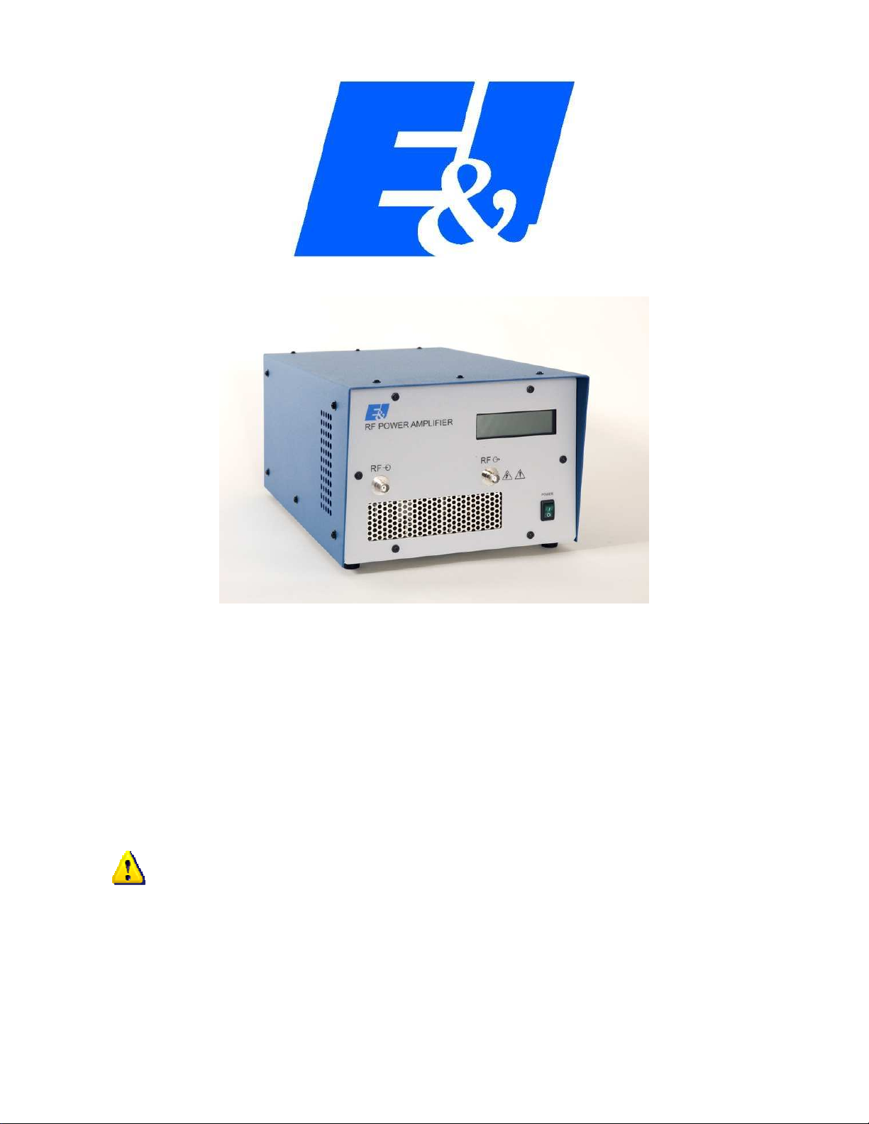
3 2 Control, Indicators and Connectors
The power switch is located on the front panel.
The BNC connectors are marked with the universal symbol for input and output.
The Back Lit LCD display indicated forward and reverse power in addition to the status.
3 3 Operating Procedure
Refer to the following procedure as a guide to operating the Model 3 5LA.
a. The input and output are connected via the front panel BNC connectors to the signal
source and load respectively.
b. The input signal should be increased gradually while observing the output voltage on
the output RF voltmeter.
c. When the Model 3 5LA is connected to a 50Ω load, the CW power output of the unit
may be read directly from the Display.
See Figure 2 for Front and Rear panel
drawings
The material contained in this document is the property of Electronics & Innovation Ltd., it is subject to change
without notice.
February 007 Page 8 of 17 Revision C
3 4 Precautions
a. The input and output of the Model 3 5LA should not be connected together. This
will cause oscillation and may damage the input preamplifier.
b. When the input signal voltage of the signal source is unknown, insert an attenuator
between it and the Model 3 5LA input.
3 5 Performance Checks
To determine the amplifier's performance carry out the following procedure.
3.5.1 Initial Check
The following check can be made whenever the condition of the unit is in question.
(i) Connect power supply. Switch on power and observe that the switch illuminates.
(ii) Connect the output of the 3 5LA amplifier to 0 dB attenuator.
(iii) Connect a calorimetric power meter (HP434 or equivalent) to the output of the attenuator.
(iv) Connect a sweep generator (Wavetek 001 or similar) capable of sweeping the frequency
range 1 to 150MHz to the input connector, ensure that the output po er of the generator is
initially set to minimum.
(v) Adjust the output level of the sweep generator to -10dBm.
(vi) Adjust the input CW signal to any frequency between 1 and 150MHz for 5W output.
If you can not attain RF power, verify that:
(a) The mains fuse is correctly selected and not blown
(b) The switch is illuminated.
If the mains fuse is not blown but you are still unable to get any RF power, either return the unit to E&I
for repair or proceed to chapter 4.
3 2 Measurement of Gain
Equipment required:
(a) Two power meters; HP 434 or equivalent
(b) Sweep/Signal Generator
(c) 0 dB Coupler
(d) Attenuator, 0 dB
The material contained in this document is the property of Electronics & Innovation Ltd., it is subject to change
without notice.
February 007 Page 9 of 17 Revision C
Connect the equipment as shown in Figure , then proceed as follows:
(a) Increase power from the signal generator to attain an output power measurement of
3 watts as indicated on the output power meter.
(b) Measure input power and calculate gain. Gain should be a nominal 50 dB
(c) Vary the frequency of the sweep generator across the band from 50 KHz to 150
MHz. Note that the variation of gain is within +/- 1.5 dB
3 3 Measurement of Harmonics
Equipment required:
(a) Sweep/Signal generator
(b) Attenuator, 0 dB
(c) Power Meter - HP434A
(d) Spectrum Analyzer
Connect the equipment as shown in Figure 3 then proceed as follows:
(d) Adjust the sweep/Signal generator at a CW center frequency of 150 MHz for an
indicated output of 5W on the power meter.
(e) Using the spectrum analyzer, check that the level of harmonics are less than - 5 dB
with respect to the carrier.
(f) Vary the frequency of the generator from 50 KHz to 150 MHz, the harmonics
should remain at - 5dBc or below.
Chapter 4 Maintenance
4 1 Introduction
The E&I 3 5LA RF amplifier requires no periodic maintenance. The instrument is unconditionally
stable and is fail safe under all load conditions. Damages can only be externally caused by an input
signal in excess of the specified IV RMS maximum.
This chapter therefore, deals only with certain fundamental procedures for fault location and with the
subsequent re-alignment procedures.
Performance limits quoted are for guidance only and should not be taken for guaranteed performance
specifications unless they are also quoted in Figure 1.
The material contained in this document is the property of Electronics & Innovation Ltd., it is subject to change
without notice.
February 007 Page 10 of 17 Revision C
4 2 Packing for Reshipment
In the event of the equipment being returned for servicing it should be packaged in the original
shipping carton and packing material. If this is not available wrap the instrument in heavy paper or
plastic and place in a rigid outer box of wood, fiberboard or very strong corrugated cardboard. Use
ample soft packing to prevent movement. Provide additional support for projecting parts to relieve
these of unnecessary shock. Close the carton securely and seal with durable tape. Mark the shipping
container FRAGILE to ensure careful handling.
4 3 Access and Layout
NB: Removal of the cover voids the warranty!
The E&I Model 3 5LA amplifier is housed in an aluminum chassis. A block diagram schematic is
illustrated in figure 4. The cover can be removed by releasing the 6 M3 screws on the side of the unit.
The rear panel supports the mains fuse holder, AC line cord and the cooling fan.
4 4 Power supply
The power supply is mounted vertically on the right hand side of the amplifier. It is a wholly self
contained unit controlled by the control board.
4 5 The Amplifier Module
The power amplifier module is mounted on the RF heat sink. To remove this module, the RF heat
sink must be demounted from the chassis. The RF drive unit sits underneath the PA section
Chapter 5 Safety:
Do not attempt to operate this unit with the cover removed. High AC, RF and DC voltages are
present. The cover prevents against electrical shock due to AC line voltages, high DC and RF fields.
Further the cover provides part of the cooling system design. Components, specifically on the RF
boards are prone to over-heat and eventual failure if the unit is operated without the cover in place.
Ensure that the load is connected to the output prior to connecting the RF input to the unit. This will
prevent high voltages being present and exposed at the output connector.
Only use the AC cord provided or equivalent.
Ensure that the mains outlet is properly grounded.
The material contained in this document is the property of Electronics & Innovation Ltd., it is subject to change
without notice.
February 007 Page 11 of 17 Revision C
Appendix:
Figures
Figure 1 3 5LA Specifications
Figure Front and Rear View
Figure 3 Gain Test Set-Up
Figure 4 Harmonic Test Set-Up
Figure 5 Block Diagram
Figure 1:
325LA Specification:
Frequency Coverage: 50 kHz to 150 MHz
Gain: 50 dB
Gain Variation: ±1.5 dB
Maximum Class A Linear Output: 5W
Harmonic Distortion:
All harmonics more than 3 dB below
main signal at 0W output; lower at
reduced power output.
Drive Source Requirements
Any signal generator, function
generator, or oscillator capable of 1
mW of output into 50 Ω
Input/Output Impedance:
Input VSWR:
Output VSWR:
50Ω
1.5:1 Maximum
.5:1 Maximum
Power Requirements:
115VAC ±10%, 50-60Hz, 3.5A;
30VAC ±10%, 50-60Hz, 1.7A
Power Output Display: Forward and Reverse power in Watts;
with an accuracy of 5%.
Noise Figure: 10 dB Maximum
Typical 3rd Order Intercept Point: +53dBm
Stability: Continuous operation into any load or
source impedance.
Protection:
Unit will withstand a +13dBm input
signal (IV RMS) for all output load
conditions, including short and open
circuit loads.
Front Panel Controls: AC Power On/Off
Front Panel Display: LCD backlit display
Front Panel Connections: RF Input RF Output
Operating Temperature: 0° to 45° C
Cooling System Forced air
Size: 7.5" H x 9.5" W x 1 .5" D
19.05 x 3.13 x 31.75 cm.
Weight: 5 ibs; 11.3kg.
Input Connector: Type BNC
Output Connector: Type BNC
Rack Mounting: 19 inch adaptors optional
The material contained in this document is the property of Electronics & Innovation Ltd., it is
subject to change without notice.
February 007
13
Revision B
Figure 2
The material contained in this document is the property of Electronics & Innovation Ltd., it is
subject to change without notice.
February 007
14
Revision B
Figure 5
Figure 4
Power
Sweep
RF
150 KHz – 300
0 dB
Attenuator
Spectrum
Power
Power
Sweep
RF
150 KHz – 300
0 dB
Attenuator
The material contained in this document is the property of Electronics & Innovation Ltd., it is
subject to change without notice.
February 007
15
Revision B
Figure 5
J
BNC
1
RS232
Control
Port
PS1
PS_ 4V
110VAC_line
110VAC_neutral
earth_gnd
SELV 5V
Inhibit
SELV 5V ret
Inhibit_ret
DC_ok
DC_ok_ret
+ 4V
+ 4V_ret
AC In
1
3
J7
TS1
Thermal switch
1
50 ohm
100W
J2
Front
panel RF
input
0d m
Controller
Fwd_in
Rev _in
TX
RX
f p_tx
f p_Vdd
f p_gnd
DC Status
PSU Enable
PSU Enable ret
DC Status_ret
ov erheat_rtn
ov erheat
gnd
gnd
+5V
A1
Fan
+ 4V
Ret
50 ohm
+34d m
P1
5
9
4
8
3
7
6
1
J6
J5
3 5LA-SCH-01 1
3 5LA RF Amp
A
1 1Tuesday , July 05, 005
Title
Size Document Number Rev
Date: Sheet of
CP1
VHF_coupler
RF_in RF_out
Fwd
Rev
IPA1
VHF_driv er
+ 4V
RF_in RF_out
Gnd
J4
IPA1_
5W_VHF_amp
+ 4V
RF_in RF_out
Gnd
J1
BNC
1
LCD1
LCD
Data_in
+5V
+5V_LED
Ground
J1

Other E&I Amplifier manuals

E&I 210L User manual

E&I

E&I 210L User manual

E&I 3100L User manual

E&I

E&I 3100L User manual

E&I 2500L User manual

E&I

E&I 2500L User manual

E&I 1000S04 User manual

E&I

E&I 1000S04 User manual

E&I A150 User manual

E&I

E&I A150 User manual

E&I 2200L User manual

E&I

E&I 2200L User manual

E&I 240L User manual

E&I

E&I 240L User manual

E&I 2400L User manual

E&I

E&I 2400L User manual

E&I 1020L User manual

E&I

E&I 1020L User manual

E&I 3100LA User manual

E&I

E&I 3100LA User manual

E&I 350L User manual

E&I

E&I 350L User manual

E&I A 1000 User manual

E&I

E&I A 1000 User manual

E&I 1140LA User manual

E&I

E&I 1140LA User manual

E&I 1040L User manual

E&I

E&I 1040L User manual

E&I 2100L User manual

E&I

E&I 2100L User manual

Popular Amplifier manuals by other brands

V-Solution V8616W-16P Installation & user manual

V-Solution

V-Solution V8616W-16P Installation & user manual

Unisound TC-30 Operation manual

Unisound

Unisound TC-30 Operation manual

SKAR Audio RP-800.1D RP-1200.1D RP-2000.1D user manual

SKAR Audio

SKAR Audio RP-800.1D RP-1200.1D RP-2000.1D user manual

AMC MMA-120 Installation and user instructions

AMC

AMC MMA-120 Installation and user instructions

ALLNIC AUDIO L-8500 OTL/OCL owner's manual

ALLNIC AUDIO

ALLNIC AUDIO L-8500 OTL/OCL owner's manual

Peavey Bass owner's manual

Peavey

Peavey Bass owner's manual

NuWaves NuPower C20R01 user manual

NuWaves

NuWaves NuPower C20R01 user manual

Boston Acoustics PA 600 user manual

Boston Acoustics

Boston Acoustics PA 600 user manual

YORKVILLE CR5 owner's manual

YORKVILLE

YORKVILLE CR5 owner's manual

ADL CruisE Questions and answers

ADL

ADL CruisE Questions and answers

Johansson 9650 instruction manual

Johansson

Johansson 9650 instruction manual

Omnitronic P-1000 user manual

Omnitronic

Omnitronic P-1000 user manual

Wieland podis?MOT FA C 3I/1I4O operating instructions

Wieland

Wieland podis?MOT FA C 3I/1I4O operating instructions

Evo SP8 user manual

Evo

Evo SP8 user manual

Yamaha PC1602 operating manual

Yamaha

Yamaha PC1602 operating manual

Technics SU-R1000 owner's manual

Technics

Technics SU-R1000 owner's manual

NEC AUA-6300E Service manual

NEC

NEC AUA-6300E Service manual

Texas Instruments TAS5102EVM user guide

Texas Instruments

Texas Instruments TAS5102EVM user guide

manuals.online logo
manuals.online logoBrands
  • About & Mission
  • Contact us
  • Privacy Policy
  • Terms and Conditions

Copyright 2025 Manuals.Online. All Rights Reserved.