•
• Channels: 20
• Two types of inputs supporting microphones and stereo
• Digital transmission
• Additional 20dB selection can be available with microphone input (for the
high-sensitivity microphone, surveillance, monitoring applications)
• Highest sampling ratios: 64k @ 16 bit x 2, frequency response 2000kHz;
HDCD sound effect
• Lowest latency (<0.5ms), and good quality of surround
• Low power consumption for a wide range of input voltage supporting
• Audio muting function when receiving weak signal or no signal
• Auto channel scanning function
Frequency: 2400-2528MHz
SWAT-2.4 Manual 5 SWAT-2.4 Manual 6
Earthquake Sound Corp. | (800) 576-7944 | www.earthquakesound.com Specifications are subject to change without notice.
Your SWAT 2.4 Comes With:
Features
Applications
stereo
computer
smart phone
•Audio transmission in a large room (DJ)
• Outdoor speakers (BBQ, Patio, Pool)
• Wireless audio transmission for surveillance
• Paging System
• Wireless microphones or loudspeakers
• iPod, sound card, CD, DVD, MP3 players or other music
players
• Wireless headphones
• Ambient music (in setting of offices, hospitals, waiting rooms)
USB
INPUT
CH
Reset/Mute
Status
USB
OUTPUT
CH
Reset/Mute
Status
(Extra Receivers Sold Separately)
(white)
(red)
1 Transmitter
2 RCA to 3.5mm Stereo Cords
1 3.5mm Stereo to 3.5mm Stereo Cord
2 110/220 Power Supplies
1 Receiver
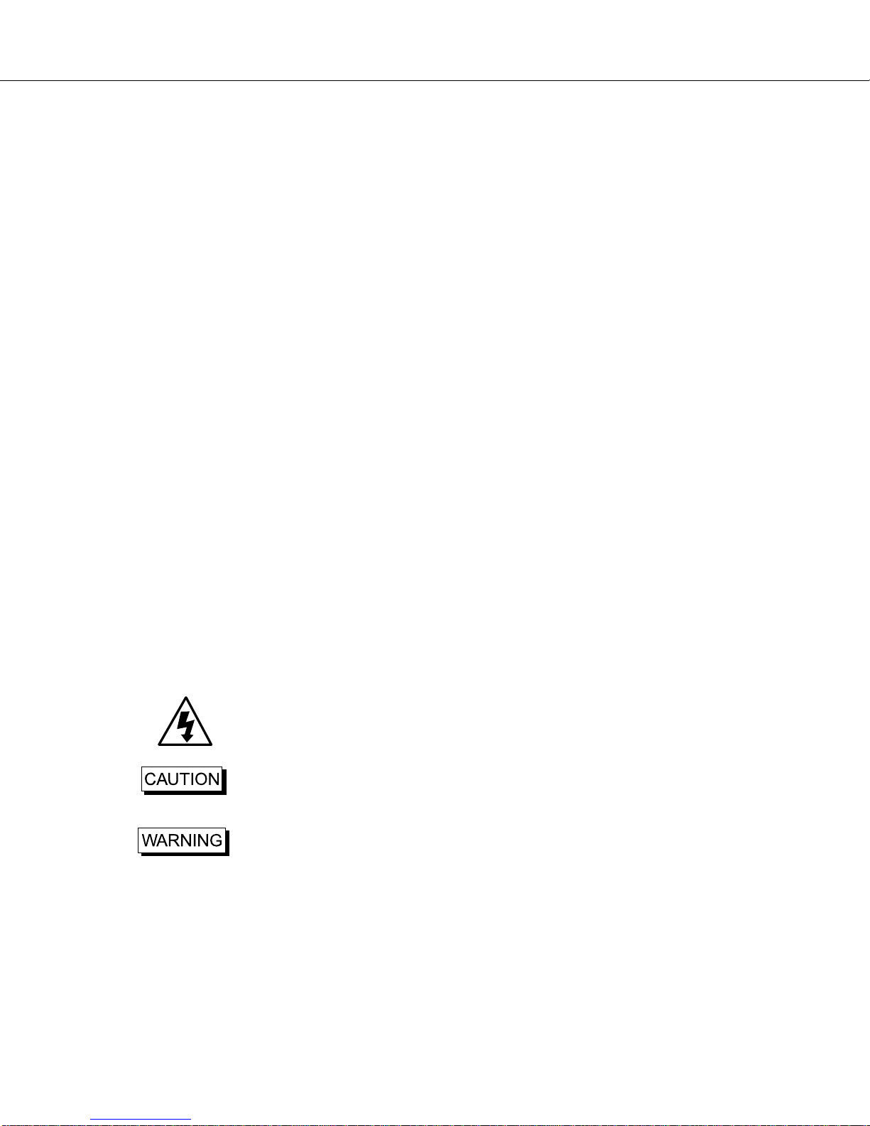
•highest quality possible. They are matched and ready to work as soon as they are plugged in and
switchedon. Youcanconnectthe110/220PowerSupplytotheTransmitterandconnecttheotherendto
awalloutlet. Or,youcanuseaUSBcableandpoweritthroughyour computer. The LED will remain on,
indicatingthattheTransmitterisworkingproperly.
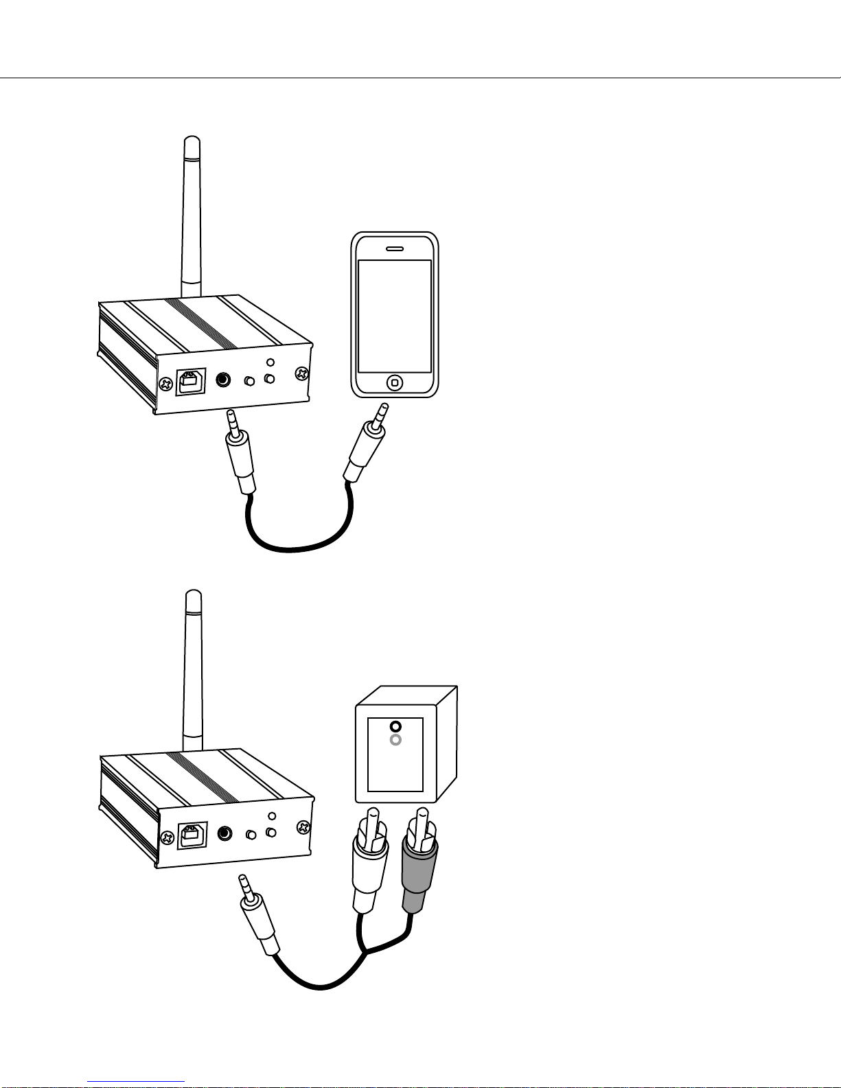
• Connection of power to Receiver: the Receivers are strictly tested before delivery to ensure the
highest quality possible. The Receiver has the same powering options as the Transmitter. When
poweredandswitchedon,theLEDlightremainsoff,indicatingthatthereceiverisworkingproperly. Ifthe
LEDlightison,theReceivercannotreceivethesignalorthereisaworkingproblem.
•AudioConnection:TurntothenextpageforinstructionsonconnectingyourSWAT2.4toaudiodevices.
Connection of power to Transmitter: the Transmitters are strictly tested before delivery to ensure the
Powering Your SWAT 2.4
Channel Changing
TheSWAT2.4’sstateofthearttechnologyincludesaneffectiveanti-jammingfeature,whichisabletofully
shield the interference from common cordless telephones, mobile phones, walkie-talkie/two-way radios,
and many other wireless facilities, leaving clear, high-fidelity, wireless audio frequency. However, in the
rare cases when the wireless Transmitter tries to broadcast through the wrong channel, you can simply
press the CH button and select a different channel. This is why the SWAT 2.4 offers 20 channels, more
than any other transceiver on the market. It also has a channel tracking mode, in which the Receiver will
automaticallyfindtheTransmitter'schannelafteritischanged.
• To manually change the channel, the Transmitter and the Receiver channels must be changed
simultaneously.
• To automatically change the channel, pair the Transmitter and Receiver as described earlier (hold down
theCHbuttononeachunitatthesametimefor3seconds,untiltheLEDlightflickers).
Pairing the Transmitter to Receiver
Before SWAT 2.4 is shipped, the Transmitter and the Receiver are already paired. However, here are
instructions for point to point pairing in the event that they are not paired or they lose connection. There
arealsoinstructionsforpointtomasspairing(connectingoneTransmittertomultipleReceivers).
PointtoPointPairing(Connecting1Transmitterto1Receiver)
•Pressand hold down theCHbuttonsonboththeTransmitterandtheReceiveratthe same timeformore
than3 seconds, untilthe LED lights are on. TheTransmitterlightwill flicker for5 seconds indicatingthat
theTransmitterandtheReceiverarepairing.
Note: If successfully paired, the LED light on the Transmitter will flicker 5 times and the Receiver will
flicker 3 times. Normally the LED light will then turn off if the receiver is successfully paired with the
transmitter.
PointtoMassPairing(Connecting1TransmittertomultipleReceivers)
•Connecting the Transmitter: Press and hold down the CH button for more than 3 seconds until the
LED light turns on, then release the button. The light will flicker for 5 seconds, within these 5 seconds
pressandholdtheCHbuttonagain. TheLEDlightwillkeepflickeringindicatingthattheTransmitterisin
mass-pairingmode.
Note:DONOTreleasetheCHbuttonuntiltheTransmitterhaspairedwithalloftheReceivers.
•Connecting the Receivers: While holding down the CH button on the Transmitter, press down the CH
button on the Receiver for more than 3 seconds. After you release the button, the light will flicker for 5
seconds indicating it is finding the Transmitter. Once the Receiver has paired with the Transmitter, the
LED light will flicker 3 times. When it is done pairing, the LED light will turn off. Repeat this process for
eachoftheReceivers. OncealltheReceivershavebeenpaired,releasetheTransmitterCHbutton.