ELPRO TPA110 SERIES Quick start guide

24
ELPRO Video Labs s.r.l.
Via della Praia 4/a FERRIERA di BUTTIGLIERA ALTA (TO) – ITALY
Tel.+ 9 0119 48778 - FAX + 9 0119 48779
TPA110series CAT5/6 VIDEO, AUDIO & IR TRANSCEIVERS
1
TPA110-M 09/06/08
Video and audio stereo Transmitter / Receiver
Compensation adjustment
Video signal in arrival indication
Dry contact for video present
Bi directional IR transmission
Carrier frequency up to 1.2MHz
Compatibile 19"

INDEX
1.0 Overview
2.0 Power supply
3.0 Settings
4.0 Installation
5.0 ideo and audio signal equalization
6.0 Accessories
7.0 Technical data
8.0 Notes
When installing the unit, please read this handbook carefully.
The manufacturer shall not be held responsible for any damage or injury caused
by use, even correct, of its products.
The data and characteristics of the product may be modified without prior notice
8.0 NOTES
232
TPA110series CAT5/6 VIDEO, AUDIO & IR TRANSCEIVERS
INSTALLATION AND USE OF THE TPA110 SERIES
TPA110
ELPRO Video Labs s.r.l.
Via della Praia 4/a FERRIERA di BUTTIGLIERA ALTA (TO) – ITALY
Tel.+39 0119348778 - FAX +39 0119348779

1.0 OVERVIEW
Thank you for buying this product. Check the contents of the packaging carefully.
It contains:
322
TPA110series CAT5/6 VIDEO, AUDIO & IR TRANSCEIVERS
ELPRO Video Labs s.r.l.
Via della Praia 4/a FERRIERA di BUTTIGLIERA ALTA (TO) – ITALY
Tel.+39 0119348778 - FAX +39 0119348779
- The kit for fastening to a 19" structure (If ordered separately)
− The TPA110 T/R dual transmitter/receiver or TPA110 IRT / IRR
− N°2 mains adapter
code ADM001
− This
handbook
If you have purchased the TPA110 IRT / IRR model, this also permits passing of
an IR (infrared) signal and will provide you with visual indication of the correct
incoming video signal.
Also, a dry contact (VIDEO) indicates that the correct incoming video signal is
present. This can be useful for remote monitoring of the condition of the incoming
video signal (present or alarm).
Transmission of the IR signal permits remote control using an IR remote control
from one environment of a unit located in another environment .
To do this, an external IR receiver will be connected to the TPA110 IRR and an IR
emitter to the TPA110 IRT or vice versa.
This permits bi-directional but not simultaneous IR transmission.

To do this, you need:
-an amplified external IR receiver normally installed on a wall and connected to
the IR IN terminals of the TPA11 IRT or TPA11 IRR;
-an IR emitter which will be connected to the IR OUT jack of the TPA11 IRR or
TPA11 IRT.
The IR emitter will be positioned on the front of the appliance to be controlled
(DVD player, Satellite etc.).
For other information regarding connection of IR devices, refer to paragraph 4.5
Line OUT
IR IN
IR OUT
Line IN
Audio out
Distortion
IR IN
IR OUT
214
TPA110series CAT5/6 VIDEO, AUDIO & IR TRANSCEIVERS
ELPRO Video Labs s.r.l.
Via della Praia 4/a FERRIERA di BUTTIGLIERA ALTA (TO) – ITALY
Tel.+39 119348778 - FAX +39 119348779
TPA110-IRT/TPA110-IRR TYPICAL SYSTEM

2.0 POWER SUPPLY
The dual TPA110 is powered only via the AC/AC adapter code ADM001 provided.
WARNING
Use of any other adapter ould damage the applian e.
Any operations must be arried out by qualified personnel.
The adapter must be inserted
in a 230 Vac/50Hz outlet.
3.0 SETTINGS
The dual TPA110 T/R has no internal settings.
There are two jumpers inside the dual TPA110 IRT / IRR to adapt use of this to
various IR receivers.
The cover must be removed to set the jumpers. Remove the top four screws to the
sides of each unit.
TPA110series CAT5/6 VIDEO, AUDIO & IR TRANSCEIVERS
ELPRO Video Labs s.r.l.
Via della Praia 4/a FERRIERA di BUTTIGLIERA ALTA (TO) – ITALY
Tel.+3 011 348778 - FAX +3 011 34877
5

The jumpers are identified as W1 and W2
W1: TTL : IR receiver with TTL output
ANALOG : IR receiver with analog output
W2: LoZ (Low impedance): : IR receiver with power output
HiZ (High impedance) : IR receiver with high impedance output
The most frequent cases are as follows
-IR receiver with power output : position 1= ANALOG; 2= LoZ
-IR receiver with TTL output : position 1= TTL; 2= HiZ
The factory setting is as follows:
1: ANALOG
2: LoZ
TPA110series CAT5/6 VIDEO, AUDIO & IR TRANSCEIVERS
ELPRO Video Labs s.r.l.
Via della Praia 4/a FERRIERA di BUTTIGLIERA ALTA (TO) – ITALY
Tel.+39 0119348778 - FAX +39 0119348779
TPA110
619
TPA 110 IRT
TPA 110 IRR

4.0 INSTALLATION
In a typical installation, the e a e usually 2 independent video sou ces to be
di ected towa ds two destinations. A CAT5 cable is used fo t ansmission between
the t ansmission and eceiving units. The CAT5 cable is the standa d cable used
fo local compute netwo ks and consists of fou unshielded twisted pai s (UTP).
The maximum lengths of the CAT5 cable that can be compensated a e:
-375mt. fo cable type AWG26
-500mt. fo cable type AWG24
-650mt. fo cable type AWG22
For monitoring and signal present type applications, sections of up to 900mt of
AWG22 CAT5 cable can be used.
In c itical noise conditions, in o de it imp ove the all- ound pe fo mance of the
system, the CAT6 cable can be used.
WARNING
Pay particular attention to grounding
of the sources and destinations (see par. 4. )
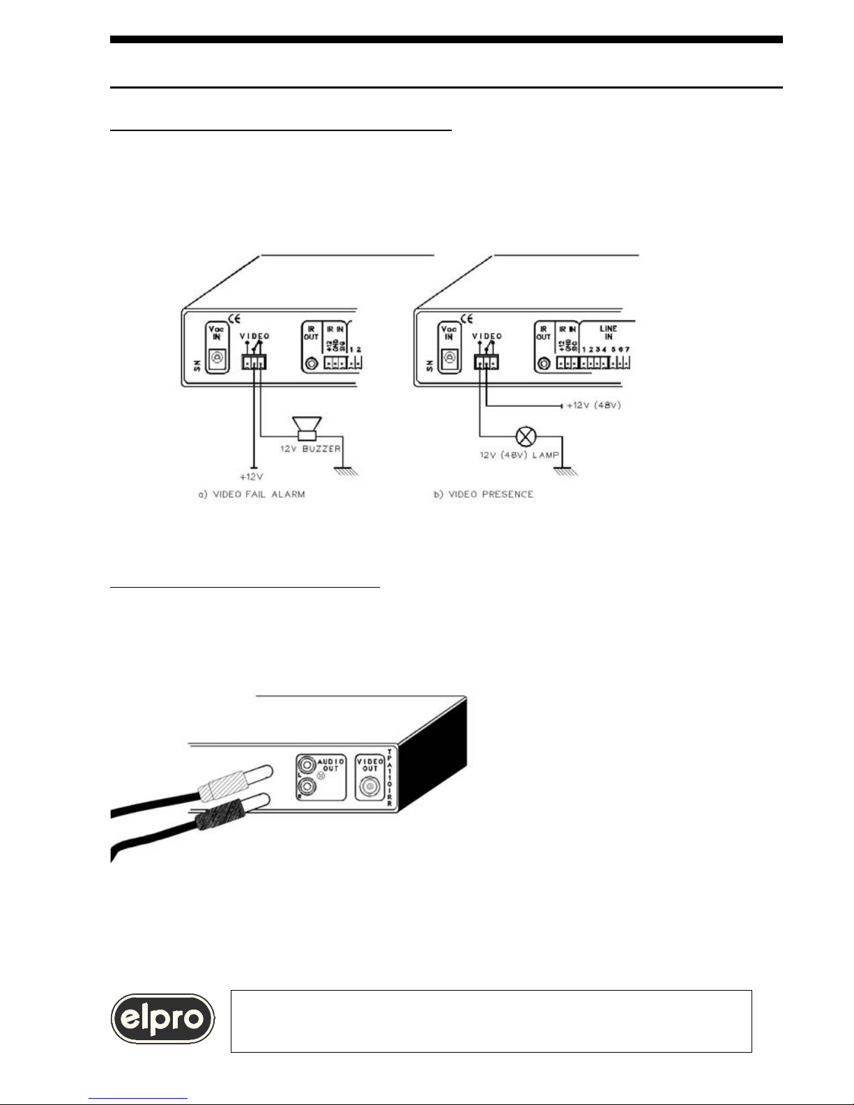
4.1 Connection of the CAT5 cable
18 7
TPA110series CAT5 6 VIDEO, AUDIO & IR TRANSCEIVERS
ELPRO Video Labs s. .l.
Via della P aia 4/a FERRIERA di BUTTIGLIERA ALTA (TO) – ITALY
Tel.+39 0119348778 - FAX +39 0119348779
300mV

5.2 Go to the TPA110 R/IRR receiver unit and connect a waveform monitor or an
oscilloscope that can be synchronized on the horizontal synchronism (H) to the output
video signal, making sure that the input of the instrument is terminated at 75Ω.
If the section of CAT5 cable is equal to or less than 50% of the maximum section
that can be compensated (see above):
5.3 Set the LONG trimmer to zero (fully counterclockwise)
5.4 Adjust the MEDIUM trimmer on the front panel of the TPA110 R / IRR receiver
unit until the amplitude of the burst on the pedestal is between 210 and 300mVpp
(If necessary, adjust the LONG trimmer turning this a few degrees in a clockwise
direction).
5.5 Check that the amplitude of the negative synchronism is between 250 and
300mV
17

of
The video destination must be connected to the BNC VIDEO OUT connector of
the TPA110 R / IRR receiving unit.
ELPRO Video Labs s.r.l.
Via della Praia 4/a FERRIERA di BUTTIGLIERA ALTA (TO) – ITALY
Tel.+39 0119348778 - FAX +39 0119348779
TPA110se ies CAT5/6 VIDEO, AUDIO & IR TRANSCEIVERS
916
WARNING
Fo optimal system functioning the g ound connections
of the sou ces and of the destinations
must be as equipotential as possible.
Different ground potentials may cause faults.

4.3 Connection of the VIDEO dry contact
The VIDEO dry contact belongs to a relay that is energized when a correct video
signal is received. This contact can be used for re ote onitoring of the
presence of the inco ing video signal or to indicate an alar if the video signal is
issing.
4.4 connection of AUDIO signals
The stereo audio source ust be connected to the RCA connectors called AUDIO
IN L and R present on the TPA110 T / IRT.
The video destination ust
connected to the RCA connectors
called AUDIO OUT L and R
present on the TPA110 R / IRR.
WARNING
The maximum permitted audio signal is +10dBm.
10 15
TPA110series CAT5/6 VIDEO, AUDIO & IR TRANSCEIVERS
ELPRO Video Labs s.r.l.
Via della Praia 4/a FERRIERA di BUTTIGLIERA ALTA (TO) – ITALY
Tel.+39 0119348778 - FAX +39 0119348779

4.5 IR (Infrared) SIGNAL connection
Usually, IR transmission is used to control an appliance (DVD player, Satellite,
etc.) located close to the transmitting unit, from the receiving station using a
remote control.
However, the circuitry used in the dual TPA110 IRT/ IRR also permits a reverse
path. Transmission may therefore be bi-directional but not simultaneous.
WARNING
If two users transmit an IR signal concurrently from the receiving and
transmitting station, a line conflict occurs and the transmissions will fail.
4.5.1 IR RECEIVER connection
The IR receiver is an electronic device able to transform IR light impulses emitted
by a remote control into an electrical signal.
The IR receiver must be positioned so that can be easily reached by the IR beam
emitted by the remote control. It is usually installed on a wall at medium-high
height. When installing the IR receiver, always comply with the manufacturer's
instructions regarding:
-Sensitivity
-Exposure to environmental and sunlight
-Settings and calibration
WARNING
Amplified IR receivers must e used
When selecting the IR receiver, the user must pay particular attention to the
operating frequency of the remote control whose signal is remotized.
Most remote controls operate at low frequencies but some manufacturers (Bang &
Olufsen, enwood, Pioneer) use remote controls with carrier frequencies of up to
1,125MHz.
WARNING
Make sure that you uy an IR receiver
that is compati le with the frequency of the remote control.
The TPA110 IRT / IRR are compati le with
frequencies of up to 1.2MHz
14 11
TPA110series CAT5/6 VIDEO, AUDIO & IR TRANSCEIVERS
ELPRO Video Labs s.r.l.
Via della Praia 4/a FERRIERA di BUTTIGLIERA ALTA (TO) – ITALY
Tel.+39 0119348778 - FAX +39 0119348779

The IR receivers available on the market are of the 3-wire type: Positive (+), ND
(0 Volt) and SI NAL.
Connect the IR receiver to the
terminals of the TPA110 IRR / IRT
unit marked IR IN +12, GND and
SIG. If the cable leading out of the
receiver is fitted with a 3.5 mm
stereo jack, cut the cable and identify
the three wires to be connected to IR
IN +12, GND and SIG terminals of
the TPA110 IRR / IRT.
For identification of the pin-out of
the receiver, refer to its user
manual.
Most of the receivers on the market
have a power SI NAL output, i.e.
able to drive an IR transmitter IR
directly. In this case, no setting is
required on the TPA110 unit as it is
factory set for this type of interface.
If the IR receiver has a SI NAL output at TTL level, the TPA110 IRR / IRT unit
must be set as described in paragraph 3.0
WARNING
If available, use of IR receivers with TTL output
ca be recomme ded as they co sume less a d cost less
4.3.2 Connection of the IR (Infrared) EMITTER
The IR emitter is an optical device able to transform en electrical signal into a
beam of IR light.
The IR emitter usually consists of a plastic capsule with a cable leading out of this
terminated with a 3.5 mm mono jack.
The capsule in which the infrared light emitter led is embedded must be
positioned, using transparent adhesive tape, on the front of the appliance to be
controlled.
12 13
TPA110series CAT5/6 VIDEO, AUDIO & IR TRANSCEIVERS
ELPRO Video Labs s.r.l.
Via della Praia 4/a FERRIERA di BUTTI LIERA ALTA (TO) – ITALY
Tel.+39 0119348778 - FAX +39 0119348779
IR REMOTE
CONTROL

Connect the 3.5 mm mono jack leading out of the IR emitter capsule in the jack of
the TPA110 IRT / IRR unit identified as IR OUT.
WARNING
The jack of the IR emitter must have the followi g co ectio s:
Tip : (A) A ode Emitti g led
Sleeve : (K) Cathode emitti g led
I side the TPA110 IRT / IRR the sleeve is co ected to grou d (GND)
13
TPA110series CAT5/6 VIDEO, AUDIO & IR TRANSCEIVERS
ELPRO Video Labs s.r.l.
Via della Praia 4/a FERRIERA di BUTTI LIERA ALTA (TO) – ITALY
Tel.+39 0119348778 - FAX +39 0119348779
IR EMITTER PIN-OUT
Jack mono 3,5mm

WARNING
Use of dual IR emitters is permitted to control up to 2 appliances.
4.5.3 Receivers with down Converter
Certain IR receivers (Xantech) compatible with frequencies of 455 Hz and
1.125MHz convert the carrier frequency down to 40 Hz.
In this case, you must also buy the modulator with related power supply which
reconverts the 40 Hz up again.
The IR emitter must be connected to the output of the modulator while the IR OUT
output of the TPA110 IRT / IRR must be connected to the input of the modulator.
remote control.
-Sensitivity
1,125MHz.
14 11
TPA110series CAT5/6 VIDEO, AUDIO & IR TRANSCEIVERS TPA110
ELPRO Video Labs s.r.l.
Via della Praia 4/a FERRIERA di BUTTIGLIERA ALTA (TO) – ITALY
Tel.+39 0119348778 - FAX +39 0119348779
USE OF DUAL IR EMITTER

This level is compati le with the std, outputs of CD,
DVD players and VHS availa le on the market.
10 15
TPA110series CAT5/6 VIDEO, AUDIO & IR TRANSCEIVERS
ELPRO Video Labs s.r.l.
Via della Praia 4/a FERRIERA di BUTTIGLIERA ALTA (TO) – ITALY
Tel.+39 0119348778 - FAX +39 0119348779

5.0 VIDEO AND AUDIO SIGNAL EQUALIZATION
The CAT5 cable introduces considerable losses on the signal in transit.
A 100-meter long AWG26 CAT5 cable attenuates 50% of the color com onents
of the video signal. As the com osite video signal is a com lex signal that does
not acce t downgrading, for each installation calibration must be erformed in
order to offset cable losses. The unit that makes this com ensation is the
receiving unit, in our case the TPA110 R / IRR.
WARNING
The TP110R / IRR unit is p ecompensated fo 50 mt of CAT5 cable
Howeve , use of a cable with a length of less than 50mt
does not affect system functioning.
The maximum lengths of the CAT5 cable that can be com ensated are:
-375mt. for cable ty e AWG26
-500mt. for cable ty e AWG24
-650mt. for cable ty e AWG22
For monitoring and signal resent ty e a lications, sections of u to 900mt of
AWG22 CAT5 cable can be used.
In critical noise conditions, in order it im rove the all-round erformance of the
system, the CAT6 cable can be used.
The CAT6 cable has the same characteristics as the CAT 5 but features
im roved insulation between the internal airs.
Losses are com ensated using the VIDEO EQ MEDIUM LONG trimmers.
Where MEDIUM and LONG refer to the length of the CAT5 cable.
The MEDIUM trimmer is used to com ensate sections of cable u to half the
maximum length indicated above. For com ensation of longer cable sections,
the MEDIUM trimmer is set to maximum (com letely clockwise) and the LONG
trimmer is adjusted.
To calibrate the system, roceed as follows, se arately for the 2 video signals:
5.1 Using a generator, send a standard video signal, for exam le the bars at
75% or CCIR17 line, to the in ut of the TPA110 T / IRT transmitter unit.
TPA110se ies CAT5/6 VIDEO, AUDIO & IR TRANSCEIVERS
ELPRO Video Labs s.r.l.
Via della Praia 4/a FERRIERA di BUTTIGLIERA ALTA (TO) – ITALY
Tel.+39 0119348778 - FAX +39 0119348779 916

Ω.
17

If the section of CAT5 cable exceeds 50% of the maximum section that can be
compensated (see above):
5.3 Tu n the MEDIUM t imme to maximum (completely clockwise).
5.4 Adjust the LONG t imme on the f ont panel of the TPA110 R / IRR eceive
unit until the amplitude of the bu st on the pedestal is between 210 and 300mVpp
5.5 Check that the amplitude of the negative synch onism is between 250 and
300mV
WARNING
The trimmers are factory set for minimum
compensation (counterclockwise)
of 50 mt. of AWG 6 CAT5 cable.
If you have pu chased the dual TPA110 IRT / IRR, a ival of a co ect video
signal is indicated by lighting up of the green led located between the two
adjustment t imme s. if the g een led is off, this means that the e is no co ect
video signal on the output.
4.0 INSTALLATION
system, the CAT6
18 7
TPA110series CAT5 6 VIDEO, AUDIO & IR TRANSCEIVERS TPA110
ELPRO Video Labs s. .l.
Via della P aia 4/a FERRIERA di BUTTIGLIERA ALTA (TO) – ITALY
Tel.+39 0119348778 - FAX +39 0119348779
ELPRO Video Labs s. .l.
Sync =
250÷300mV
Bu st =
210÷300mV
LED PRESENZA VIDEO
Audio LEVEL trimmers

Presence of the incoming video signal is also indicated by a relais whom contacts
are available to the terminals VIDEO.
Drawing represents the released contacs.
For other information regarding connection, refer to paragraph 4.3
For the stereo audio signal, losses due to the cable are not so significant as for
the video signal.
However, for long sections of cable, the output level of the audio signal must be
calibrated in order to compensate for losses due to the cable.
To do this, turn the LEVEL L and R trimmers in a clockwise direction until the
audio signal level reaches that desired.
ELPRO Video Labs s.r.l.
Via della Praia 4/a FERRIERA di BUTTIGLIERA ALTA (TO) – ITALY
Tel.+39 0119348778 - FAX +39 0119348779
TPA110series CAT5/6 VIDEO, AUDIO & IR TRANSCEIVERS
6 19

6.0 ACCESSORIES
The unit is supplied complete with:
- The mains adapter code ADM001
The following are available on request:
-A kit of accessories for fastening of units to a 1 " rack.
Fastening is possible with a single unit using the tabs code 0106 014, or with a
second, mechanically compatible Elpro unit to the side.
Assembly of the accessories for assembly in a 1 " rack is shown in the drawing.
TPA110series CAT5/6 VIDEO, AUDIO & IR TRANSCEIVERS TPA110
ELPRO Video Labs s.r.l.
Via della Praia 4/a FERRIERA di BUTTIGLIERA ALTA (TO) – ITALY
Tel.+3 011 348778 - FAX +3 011 34877 20 5
This manual suits for next models
2
Table of contents
Popular Transceiver manuals by other brands

Navman
Navman VHF 7000 owner's manual

Simrad
Simrad NAIS-400 instruction manual

Uniden
Uniden UH037SX-2NB user manual

Racal-Tacticom
Racal-Tacticom PRM 4515U Technical manual

Wulfsberg Electronics
Wulfsberg Electronics COBHAM RMS-555 pilot's guide

Yaesu
Yaesu FTDX5000 - SOFTWARE UPDATE AND VERSION... Software update

Wintec
Wintec 45V user manual

Leeham
Leeham LH80 Installation and operation instructions

Lime Microsystems
Lime Microsystems LMS7002MR3 Programming and Calibration Guide

Epiq Solutions
Epiq Solutions Sidekiq Stretch Hardware user manual

Kenwood
Kenwood NEXEDGE NX-800H Service manual

Yaesu
Yaesu FT-5100 Technical supplement