EASTERN INFO-COM iDRS-5000 User manual

-1-
OPERATION MANUAL
[iDRS-5000]
EASTERN INFO-COM INC.
http://www.easterninfo.com

-2-
FCC NOTICE
THIS DEVICE COMPLIES WITH PART 15 OF THE FCC FULES.
OPERATION IS SUBJECT TO THE FOLLOWING TWO CONDITION:
(1) THIS DEVICE MAY NOT CAUSE HARMFUL INTERFERENCE, AND
(2) THIS DEVICE MUST ACCEPT ANY INTERFERENCE RECEIVED,
INCLUDING INTERFERENCE THAT MAY CAUSE UNDERSIRED
OPERATION.
This equipment has been tested and found to comply with the limits for a Class B digital device,
pursuant to part 15 of the FCC Rules. These limits are designed to provide reasonable protection
against harmful interference in a residential installation. This equipment generates, uses and
can radiate radio frequency energy and, if not installed and used in accordance with the
instructions, may cause harmful interference to radio communication. However, there is no
guarantee that interference will not occur in a particular installation. If this equipment does cause
harmful interference to radio or television reception, which can be determined by turning the
equipment off and on, the user is encouraged to try to correct the interference by one or more
of the following measures :
-Reorient or relocate the receiving antenna.
-Increase the separation between the equipment and receiver.
-Connect the equipment into an outlet on a circuit difference from that to which
the receiver is connected.
-Consult the dealer of an experienced radio/TV technician for help.
NOTE : The manufacturer is not responsible for any radio or TV interference caused by
unauthorized modifications to this equipment. Such modifications could void the user’s
authority to operate the equipment.

-3-
1. iDRS-5000 Board Manual
1. Video Channel : 4CH, 8CH
2. Record Fream
-Display : 100/120(fps)
-Recording : 100/120(fps)
3. Sensor/Alarm
-DI : 8EA
-DO: 4EA
4. Recording Resolution : 320 x 240
5. Board Minute explanation
4
3
1
6
5
2

-4-
①DIO Cable Link Connector
②Watch dog Cable Link Connector
③Video Channel 1~4 Connector
④Video Channel 5~8 Connector
⑤NTSC/PAL Select Connector
⑥Video Channel 1~4 BNC Connector
7. Notice .
-When in using ③,④you need some ‘guide fins’, made by Eastern Info Com
8. NTSC/PAL Select
-PAL is on PCI Slot side
-NTSC is on the other side
9. DO Execution : NO NC COM
10. Driving Program
-Use only iDRS-Programs, Provided from Eastern Info Com

-5-
iDRS-5000 Digital DIO Pin Configuration
13 25
ο
οο
οο
οο
οο
οο
οο
οο
οο
οο
οο
οο
οο
1 14
Pin # I/O COLOR
1Sensor 1 BLACK
2Sensor 2 BROWN
3Sensor 3 RED
4Sensor 4 ORANGE
5Sensor 5 YELLOW
6Sensor 6 GREEN
7Sensor 7 BLUE
8Sensor 8 PURPLE
9GND BLACK
10 GND BLACK
11 GND BLACK
12 GND BLACK
13 GND BLACK
14 D/O 1 NC WHITE
15 D/O 1 COM GRAY
16 D/O 1 NO BLUE
17 D/O 2 NC WHITE
18 D/O 2 COM GRAY
19 D/O 2 NO YELLOW
20 D/O 3 NC WHITE
21 D/O 3 COM GRAY
22 D/O 3 NO ORANGE
23 D/O 4 NC WHITE
24 D/O 4 COM GRAY
25 D/O 4 NO PURPLE

-6-
2. Power On
1. To check your camera image, You should turn on cameras, monitor, sensor, etc, before you turn on iDRS-5000.
2. Turn on iDRS-5000.
[POWER] lamp will light on, disk check(red LED) blinks then WINDOWS 98 starts. After booting main
screen will appear as follows.
3. Main Screen
1) Activated icon will be turned green and show TIP of each icon, when mouse pointer get close to each icon.
Inactivated icon will be turned yellow.
2) When consecutive recording, red lamp is displayed in OSD(Camera Name).
3) When motion recording, blue lamp is displayed in OSD(Camera Name).
4) When sensor recording, yellow lamp is displayed in OSD(Camera Name).
5) When [Record] lamp is on and off, it is consecutive recording, [Motion] lamp is on and
off, it is motion recording, [Sensor] lamp is on and off, it is sensor recording.
6) Put your mouse pointer to image screen, click left button to enlarge corresponding screen. And click
right button to extend to full screen.
7) Click right button in full screen mode to back to main screen.

-7-
Zooming In
Zooming Out
Focus gets further.
8) [System Shutdown] If you click this icon, confirmation message will appear as follows.
If you select [OK] system will be shut down and automatically power OFF.
9)
10)[Motion Tracer] Enlarge a screen in which the motion is detected.
11) [Set up] Change iDRS-3000 set up configurations. (Refer to the ‘2. Set up Change’)
12) [Image search/Playback] Search recorded image.(Refer to the ‘3. See * 3. Image Search)
13) [Camera ON/OFF] Camera ON/OFF icon. When P/T control select camera as 13).
If you click this icon power off th4e corresponding camera.
14) Camera Pan/Tilt Control Button.
[◀-left / ▶-right / -up / -down]
15) [Zoom] Control motorized zoom lens.
16) [Focus] Control camera lens focus.
17) [Light ON/OFF] Control Lighting Equipment.
18) Clock : Indicate present time and date.
19) In case you need to shut down the system by force, push POWER button for 4-5 seconds. But shutting down by
force may cause fatal damage to the system itself and data. Please always use [Shut Down] button.
Focus gets closer.
Single-Screeen
Rotational Display
Quad(4)-screen Rotational
All-Channel Display.

-8-
3. Set up change ( )
1) [Camera set up]
▶Put each camera name for OSD(On-Screen Display) zone.
▶Set up each camera.
▶If you click system will automatically detect connected camera.
▶[TOTAL BOARD] : Show total number of iDRS-CARDs.
▶[TOTAL SPEED] : Show maximum recording speed.
Click to select camera to
change camera name iDRS CARD number Input camera number

-9-
2) [Schedule]
▶Set up each group. Total 10 groups are available (programmable)
- Select group.
- Set the days of the week.
- Connect cameras, motion detectors(software sensor), (external) sensor and D/O.
▶If you want to record specific time, please designate [START TIME], [END TIME].
- 00:00 to 00:00 means whole day(24 hours) recording.]
▶After designation, active corresponding group.
▶Automatically connect Set up date, Camera, Sensor, D/O by click. It is not saved with disconnected camera,
sensor, D/O, and also disconnected date.(click once again to disconnect.)
3) [Recording Speed]
▶Designate normal recording speed (Frame Rate).

-10 -
(Separate frame rate for each camera is available.)
▶Designate motion-detected recording Frame Rate.
(Separate frame rate for each camera is available.)
▶When sensor recording designate camera FRAME.
(Separate frame rate for each camera is available.)
▶[Switch Speed] : Adjust interval for rotational display model.
▶[Motion Delay] : Keep on recording after motion detection is finished, during indicated time.
▶[Sensor Delay] : Keep on recording after sensor detection is finished, during indicated time.
▶[Sensor Beep] : Activate BEEP sound on sensor detection.
▶[Proportion] : When activated, only 1, 4, 9, 16 divisions are available, to keep the horizontal and vertical ratio of
each screen.
▶[Image Quality] : Adjust compression rate. At 100% quality, recorded image is clear and vivid but the size of a
frame is bigger (15-20KB). At lower percentage (higher compression rate) image quality is relatively low but
size of a frame is smaller (3-8KB). 34-50% is recommended.
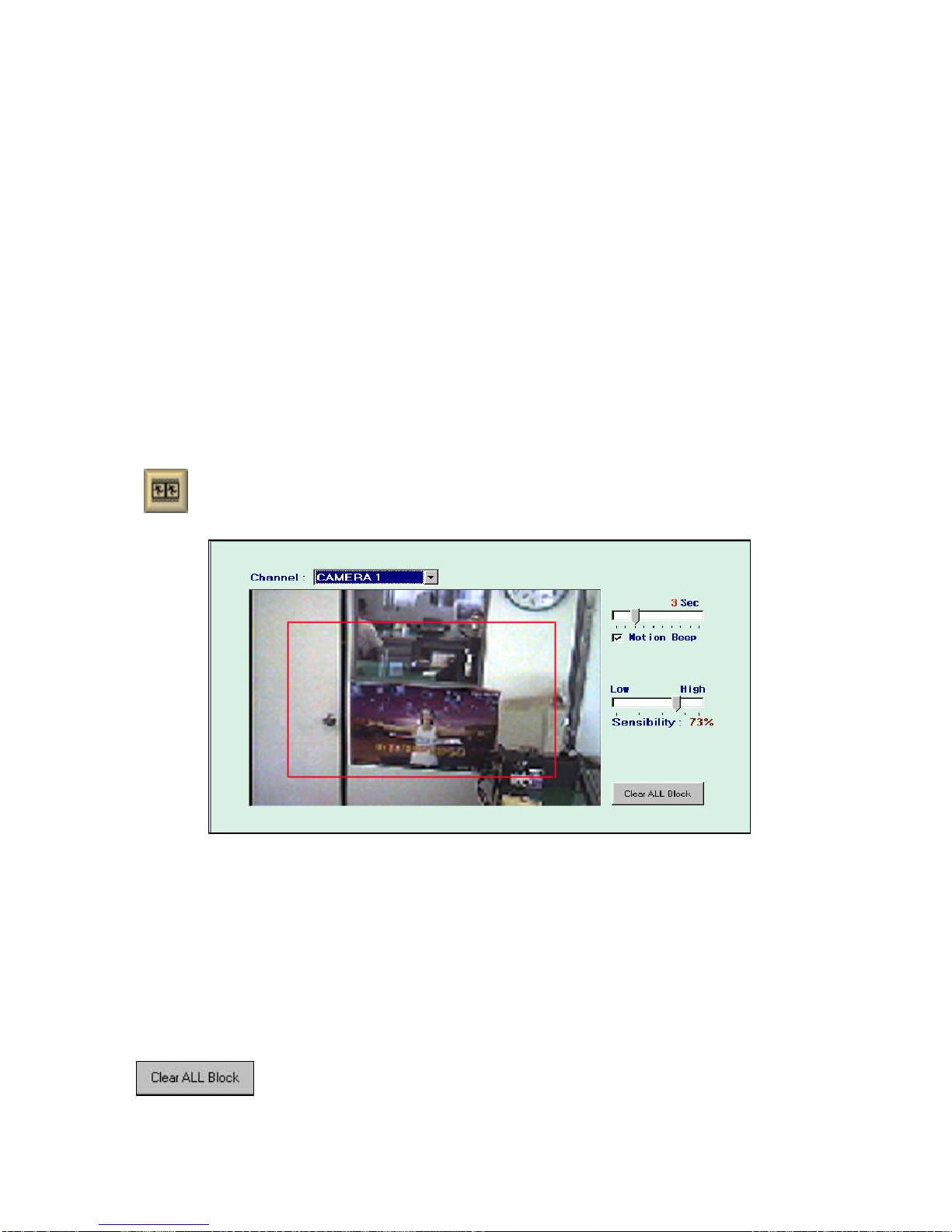
(4) [Motion] Motion Detector configuration
▶Set up motion detection zone. It would be seen in red square(Maximum 10 areas per camera).
▶If motion detector is connected in ‘Schedule’menu but no detection zone is defined, system will recognize
whole screen as a detection zone.
▶When motion recording mode, detection BEEP sound can be activated/inactivated.
▶Detected motion is seen in blue unit square, and indicating red ‘MOTION DETECTON’.
▶[SENSITIVITY] : Setting sensitivity of software motion detector
At high sensitivity even the very trivial motion will detected.
Adjust it to proper level.(30% -40% is recommended)
▶Delete all motion detection zone.

-11 -
4. Image Search
( )
5) [Password]
6) [Close Set up] : Back to main screen.
1) [Camera(Channel) Number] : Select camera number to playback.
▶Set up password, to prevent other person
than operator from changing setup.
▶If you set up new password click [APPLY]
to use new password.
▶Please do not forget password.
(Set up change is impossible)

-12 -
2) [Date select] : Recorded date is checked with red mark automatically.
Click date to search.
※Previous Month -Next month
If there is no recorded data in other month(s) month selection buttons are inactivated.
3) Playback Screen adjustment
:Contrast of search screen. (Level control)
: Brightness of search screen. ( Level control)
4)Other functions
[Media information] Check available disk capacity and frame size.
.
[FDD backup] Save present screen in image file (JPG or BMP) to the floppy disk.
※In 1 FDD about 100 image cuts can be saved by JPG file or 30 cuts by BMP file
High speed Playback
Move back 1minute Play Stop Move forward 1minute
Move back 1 cut Move forward 1 Cut
To first cut of
recorded screen To last cut of
recorded screen
Low level
High level
Disk capacity is 9270MB, recorded
capacity is 1090MB. 11% is used.
Average recording capacity is 8.46KB.
So the expected recording period is
about 13 days (311 hours 40 minutes).

-13 -
`
[Print] Print out present image. Stop the image to print and click.
Selected screen is printed by printer.(Continuous print is available for 30 cuts)
Time stamp (YYYY/MM/DD HH:MM:SS) will automatically be included.
Assigning cut name and printing is available, click [set up]to set up printer driver
[Time search] Select time(hour,minute) for fast and accurate search/playback
《: Start Search》
[Close Play-Back Screen] Back to main screen.
PRINT OUT 1 cut from present image without
name.
BACK-UP 1 cut, now seen in monitor by JPEG
file in Floppy disk.
Table of contents