Eastey EC Series User manual

EC
Eastey EC Series
Variable Speed Conveyors
User Guide
EC1248, EC1848 & EC2472


EC
Eastey EC Series
Variable Speed Conveyors
User Guide
Revised 01/11/2022
P/N C001000 Rev C1
Copyright and Trademarks
Copyright ©2017-2022 Engage Technologies Corporation
All rights reserved. All trademarks and brand names
are the property of their respective owners.
Eastey
7041 Boone Ave. N.
Brooklyn Park, MN 55428
Phone: (763) 428-4846; Fax (763) 795-8867; 1-800-835-9344
www.eastey.com
EC1248, EC1848 & EC2472


Contents:
Safety ............................................................................................................................. 7
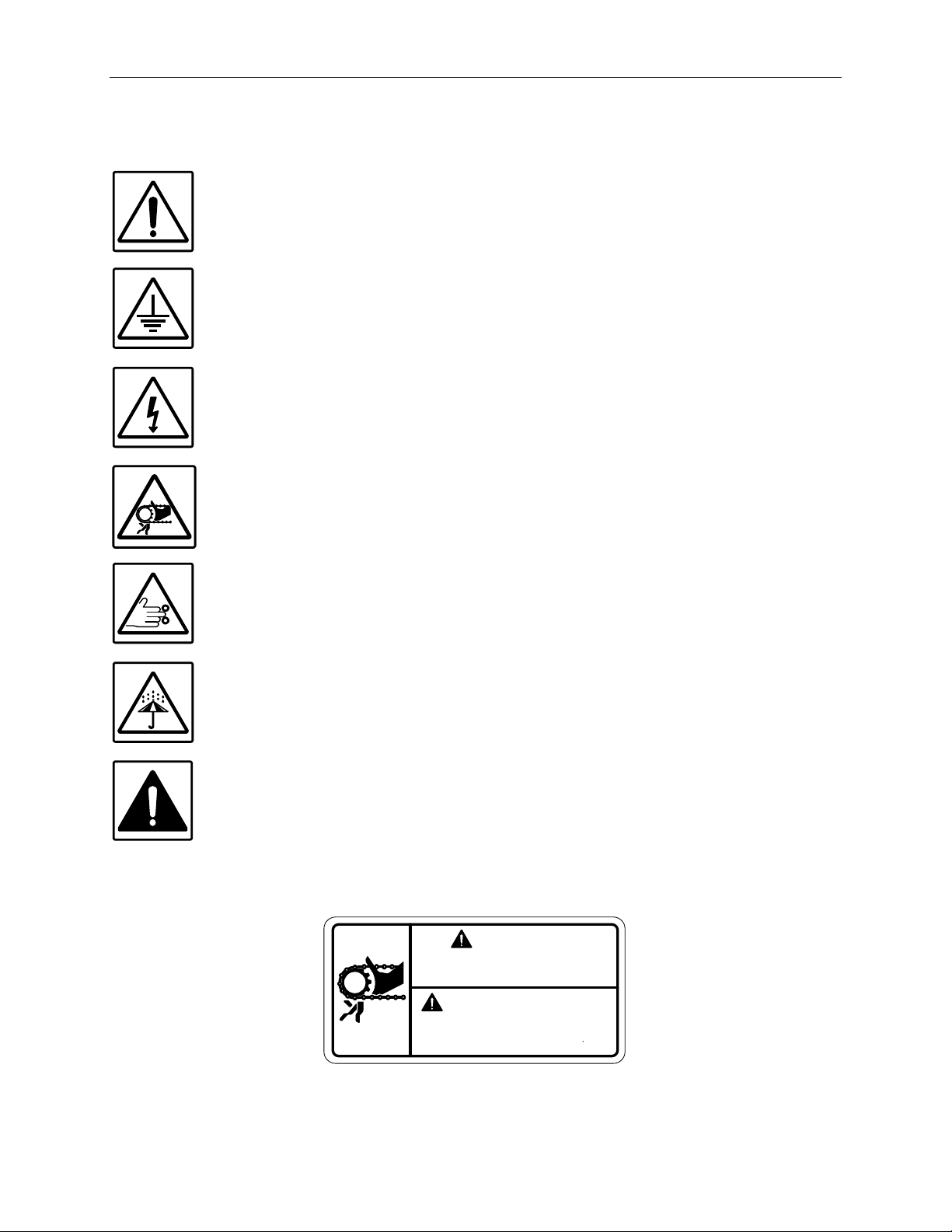
Explanation of Symbols ................................................................................................ 8
Introduction ................................................................................................................... 9
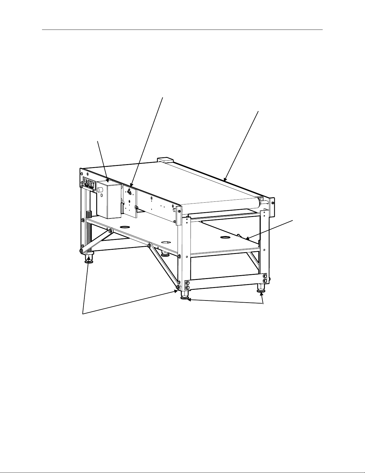
Eastey EC Series Variable Speed Conveyor Overview................................................ 9
Specifications ............................................................................................................. 10
Dimensions................................................................................................................. 12
Installation ................................................................................................................... 13
Optional Casters......................................................................................................... 13
Move Conveyor into Operating Location .................................................................... 13
Height Adjustment and Leveling................................................................................. 13
Location Requirements............................................................................................... 16
Mounting the Ink Jet Printer........................................................................................ 17
Guide Rail Assembly and Installation (C0000501 or C0000511)................................ 18
Operation ..................................................................................................................... 19
Power ......................................................................................................................... 19
Control Box................................................................................................................. 20
Adjustments ................................................................................................................ 21
Height Adjustment and Leveling................................................................................. 21
Conveyor Tension Adjustment .................................................................................... 23
Advanced Speed and Control Function Adjustment ................................................... 24
Maintenance ................................................................................................................ 27
Cleaning the Belt ........................................................................................................ 27
Changing the Belt ....................................................................................................... 27
Troubleshooting.......................................................................................................... 29
Parts List...................................................................................................................... 32
Conveyor — EC1248, EC1848 & EC2472 ................................................................. 32
Option / Accessory Kits — EC1248, EC1848 & EC2472............................................ 34
Appendix A: Electrical Schematic ............................................................................. 35
Warranty Statement .................................................................................................... 36
Customer Support....................................................................................................... 38


Safety 7
Safety
General Safety Precautions
Before installing, operating or servicing this equipment, please read the following
precautions carefully:
•This machine is equipped with moving belts. Do not place hands near the rear of this
unit when the belts are moving as fingers may be pinched where belts enter the
frame.
•Do not attempt to open or work on the electrical box, junction boxes or other
electrical components of the unit without first disconnecting power to the machine.
Electrical shock hazard exists if power is not disconnected.
•Do not by-pass any factory-designed safety features such as guards, interlocks,
switches, etc.
•Do not place hands or body inside the confines of the machine unless all
mechanisms are securely fastened and the electrical supply is shut off.
•Never provide service or clear a box jam when machine is running.
•Do not wear loose clothing such as ties, scarves, jewelry etc. Long hair should be
pulled back and/or covered while operating this machine.
•Do not stand or climb on any part of the conveyor or frame.

8Safety
Explanation of Symbols
Caution sign or Safety Alert symbol. Indicates caution, be alert, Your safety
is involved. Knowledge of safe operation is required.
Ground symbol. Indicates ground. Use Class-3 (lower than 1000) cable to
ground to earth. Incomplete grounding may lead to electrical shock.
Electrical hazard. Indicates electrical danger. Only a trained electrician can
uncover the electrical panel or box.
Entanglement hazard. Moving parts can crush and cut. Keep hands and
fingers clear of moving parts. Shut down the machine before performing
maintenance. Keep hands and fingers clear of belt, rollers, and drive
mechanism before starting conveyor and while it is in operation.
Pinch hazard. Do not place your hands or fingers in the moving mechanism.
Shut down the machine before performing maintenance.
Moisture hazard. Keep equipment dry. This equipment is designed for
indoor operation in a typical clean, dry factory environment, protected from
rain and moisture. Do not operate the machine in any extremely wet or oily
environment that may exceed operating specifications.
Warning symbol. Indicates a hazardous situation which, if not avoided could
result in death or serious injury.
A warning indicates a situation potentially more severe than indicated by a
caution message but not immanent as a danger message.
The warning symbol is associated with messages for conditions as shown below.
CAUTION
PRECAUCIÓN!
¡
KEEPHANDS CLEAR! MOVING
precausión mantenga sus
móvlies pueden aplastar y cortar
manos alejandas partes
PARTS CAN CRUSH AND CUT!

Introduction 9
Introduction
Eastey EC Series Variable Speed Conveyor Overview
Note: Conveyors are shipped collapsed to minimum height to
conserve space during shipping. Conveyor legs are
adjustable for height and leveling, and angle leg extension
brackets are provided in legs at all four corners of the
conveyor to provide stability at increased conveyor height.
Movable
Magnetically
Attached Control
Box Can Be
Repositioned As
Desired Along
Either Side Plate
Side Plates
Pre-Drilled for
Easy
Attachment of
Standard
Equipment
Such as
Guide Rails
Mounting Plate Is
Pre-Drilled for
Easy Attachment
of Supports for
Standard Items
Such as Print
Heads or Touch
Screen Operator’s
Panel
Adjustable
Leveling
Legs
(Optional
Locking
Casters
Are Also
Available)
Storage
Shelf
Extendable /
Retractable
Angle Leg
Extensions
(Shown
Retracted As
Shipped To
Conserve
Space)

10 Introduction
Specifications
Model
Nominal Conveyor Size
(width × length)
Width
(A)
Height
(B)
Length
(C)
EC1248
12 in. × 48 in.
30.5 × 122 cm
20.2 in.
51.3 cm
See Table Below
Based on Leg Length
48.9 in.
124.2 cm
EC1848
18 in. × 48 in.
45.7 × 122 cm
26.2 in.
66.5 cm
See Table Below
Based on Leg Length
48.9 in.
124.2 cm
EC2472
24 in. × 72 in.
61 × 183 cm
32.2 in.
81.8 cm
See Table Below
Based on Leg Length
72 in.
183 cm
Model
With 9” Leveling Legs
With 17” Leveling
Legs
With 9” Leveling Legs
and Locking Casters
With 17” Leveling
Legs and Locking
Casters
All Models
20 in. - 33.5 in.
50.8 cm – 85.1 cm
28 in. - 41.5 in.
71.1 cm – 105.4 cm
24 in. - 37.5 in.
61 cm – 95.3 cm
32 in. - 45.5 in.
81.2 cm – 115.6 cm
Explanation of Model Numbers
•E = Manufactured by Eastey Enterprises Inc., division of Engage Technologies.
•C = Conveyor. EC Series variable speed conveyor offer a reliable stand-alone
product transport for primary or secondary product marking, and make a
convenient add-on infeed or exit conveyor to existing case taping or shrink
wrapping equipment.
•_ _ = 12, 18, or 24 — First two digits indicate the nominal width of the conveyor
belt in inches: 12, 18, or 24-inch conveyor lengths are available.
•_ _ = 48 or 72 — Remaining two digits indicate the nominal total length of the
conveyor in inches: 48 or 72-inch conveyor lengths are available.
•V0 = Voltage and Phase, 110V 5A single phase. All models are available
configured for 110V 5A single phase. Only single phase is offered.
Conveyor Specifications
Machinery Makeup Industrial strength ¼ inch thick steel, powder
coated for durability.
Variable Speed Up to 100 fpm.
Conveyor Height Adjustment20 in. to 33.5 in. with 9-in. leg and without casters;
23 in. to 41.5 in. with 17-in. leg and without casters;
24 in. to 37.5 in. with 9-in. leg and with casters;
27 in. to 45.5 in. with 17-in. leg and with casters.
Electrical Requirements 110~115V 5A Single Phase.

Introduction 11
Standard features
•Magnetic control box can be mounted on either side of conveyor to
accommodate conveyor orientation and operator convenience.
•Pre-drilled mounting plate for printer brackets (one mounting plate is provided
standard) makes for easy integration with ink jet printers and other equipment.
•Shelf included for storage of various items such as spare printheads, printer and
LED control boxes, spare ink, and more.
•Small space saving footprint
•Seamless self-tracking belt
•¼ inch cold rolled steel
•Variable speed drive
•Optional guide rails available
•Safety cover over pinch points
•Adjustable conveyor height
•Smooth, consistent belt speed
Eastey Conveyor Optional Accessories
Additional Print Head Mounting Plate Predrilled to mount full family of Squid
Ink Printing Systems.
Guide Rails Single or dual optional heavy-duty side
rails are available for box or primary
product guidance to align product for
consistent print (sold separately per
side).
17-Inch Threaded Rod Legs For up to 8” additional adjustable
conveyor height if required.
Casters Lockable casters for easy movement
throughout the plant.

12 Introduction
Dimensions
With Leveling Feet (Standard)
With Optional Locking Casters

Installation 13
Installation
Carefully unpack the outer carton and shipping material. Avoid damaging the conveyor
frame.
Remove shipping bolts or brackets securing the conveyor to the shipping base. Lift the
conveyor off the shipping base.
CAUTION! The conveyor may require more than one person to move
safely off the shipping base.
Optional Casters
The conveyor is delivered flat leveling feet, standard. If the conveyor is ordered with
optional locking casters, the casters are installed at the factory and the conveyor is
delivered with them installed, attached to the bottom of the threaded leveling legs.
Move Conveyor into Operating Location
Move the Eastey EC Series Variable Speed Conveyor to the desired location where it
will be operating. If the conveyor is equipped with the standard leveling feet, it may
require some lifting, but will easily skid across a smooth level floor surface. If you have
purchased the optional locking casters you can roll the conveyor easily over a smooth
flat surface. Move each caster lever to the locked position to keep the conveyor from
moving.
Height Adjustment and Leveling
Conveyors are shipped at minimum height to conserve space during shipping so it is
likely you will need to increase the conveyor height to bring it up to the desired height of
your conveyor line. All four legs at the corners of the conveyor are adjustable for height
and leveling, and two mechanisms allow for height adjustment: threaded-rod legs and
leg-extension angle brackets.
Threaded-rod legs: threaded-rod legs are adjustable for their total length (less
approximately ½ inch of threads required to secure the legs in the bottom of leg-
extension angle brackets) and provide for fine adjustment to level the conveyor at the
required conveyor height.
Leg-extension angle brackets: Extending or retracting the leg-extension angles
provide five inches (5”) additional height when extended, or less five inches (5”) when
retracted. When extending the leg-extension angles, it is recommended to reposition the
leg brace strap for stability. See the illustrations on the following page.

14 Installation
Raising the Conveyor
Begin raising the conveyor by turning the feet clockwise, as viewed from above.
Note: Thread-locking compound is used to secure the feet or
optional casters to the leveling leg.
If you will be raising the conveyor more than 7/8inches from the minimum shipping
height, thread the threaded-rod leg all of the way out of the bottom of the conveyor leg-
extension angle bracket and thread a 1”-8 UNC standard nut (4 provided – one for each
leg) onto the threaded rod, and then re-thread the threaded rod back into place. The 1-8
UNC nut will function as a jam nut to lock the conveyor at the level height when the
conveyor is adjusted and leveled at the required height.
Note: An open-end wrench or channel-style wrench with a 1-½”
opening is required for the 1”-8 UNC standard nuts.
Raise Raise
1”-8 UNC
Nut
(1 Each Leg)

Installation 15
Leg Extension Angle Brackets
For fine-adjustment of the leg height, twist to thread the threaded-rod leg into or out of
the conveyor leg angle bracket to adjust each leg up or down. (Loosen the 1”-8 UNC
standard nut when applicable to allow adjustment of the threaded rod.)
If the conveyor is to be raised more than 5-7/8inches in height from minimum shipping
height, extend the leg extension angle brackets on all four corners. Instructions for
extending the leg extension angle brackets are provided below.
1. Temporarily remove and save the hardware that fastens the leg extension angle
bracket and leg brace bar. Remove both ends of the leg brace bar, as the brace
bar will be repositioned to other holes when it is refastened to the leg extension
angle bracket.
2. Reposition the leg extension angle to align the upper holes in the leg extension
angle with the bottom holes in the vertical leg of the conveyor base frame.
3. With the leg extension angle bracket extended, use the same hardware removed
previously to refasten the leg extension angle bracket to the conveyor base
frame.
4. Reposition the leg brace bar as shown, to align the top hole with the hole closer
to the corner in the side brace of the conveyor base frame, and to use the upper
of the two holes near the bottom of the leg extension angle bracket.
Note: If higher conveyor height is required, optional 17-inch long
threaded rod legs are available to provide up to 8 inches of
additional adjustable conveyor height.
12 3 4

16 Installation
Height Fine-Adjustment and Leveling
For fine-adjustment of the leg length for fine-adjustment of height or for final leveling of
the conveyor, first loosen the 1”-8 UNC standard nut, if applicable, and then twist the
threaded-rod leg into or out of the conveyor leg angle bracket.
Note: An open-end wrench or channel-style wrench with a 1-½”
opening is required for the 1”-8 UNC standard nuts.
Location Requirements
When installing the Eastey EC Series Variable Speed Conveyor please be aware of the
following considerations:
1. The mounting surface is flat and level.
2. Conveyor or packing table height.
3. Alignment with packaging line.
A packing table may be provided at the in feed end where items may be placed before
sending them on to the conveyor. It can also be convenient to have a pack table at the
exit end of the conveyor line. It is essential that the conveyor be at the same
approximate height as other components of the line.
The conveyor should be placed on a flat, level floor so that it does not rock or move. We
recommend that the machine be securely locked in place when used.
Lower Raise Lower Raise
Lock Unlock Lock Unlock
1”-8 UNC Nut

Installation 17
Mounting the Ink Jet Printer
There are mounting holes predrilled that allow you to mount a variety of printing
systems on the Variable-Speed Conveyor. Refer to the User Guide that came with
your printer for mounting instructions.
The illustrations that follow in this section show examples of possible locations for
attaching mounting brackets for some common printer configurations. Your printer
configuration may be different.
Example of Variable Speed Conveyor with CoPilot Mounting Bracket
A pre-drilled and tapped mounting Bracket Support Plate is provided for installation of
the Printer Mounting Bracket. Use four (4) ¼-20 × 1” hex-head bolts with flat washers
and lock nuts to fasten the Baseplate Connector Clamp to the Bracket Support Plate.
Note The above example shows a CoPilot Max system on 2005061
kit. Other printers can be mounted in a similar way.
Note Threaded holes in the conveyor side plates are provided on
both sides of the conveyor for mounting Guide Rail mounting
rod brackets.
CoPilot
Controller
CoPilot
Print Head
Printer
Mounting
Bracket
Baseplate
Connector
Clamp
Bracket
Support
Plate
Pairs of holes
pre-drilled and
tapped for Guide
Rail mounting
rod brackets

18 Installation
Example of Variable Speed Conveyor with Squid Ink PZ Mounting Bracket
or DOD Mounting Bracket
For a Squid Ink PZ or DOD printer, fasten the applicable mounting bracket to the
Variable Speed Conveyor side plate as shown in the illustration below. Refer to the
User Guide that came with your printer for mounting instructions.
Note Threaded holes in the conveyor side plates are provided on
both sides of the conveyor for mounting PZ or DOD
mounting brackets.
Guide Rail Assembly and Installation (C0000501 or C0000511)
Drilled and threaded holes are provided in the Variable Speed Conveyor side plates in
both sides for attaching a Guide Rail to either side of the conveyor.
PZ Mounting
Bracket
DOD Mounting
Bracket
Guide Rail Shafts
Guide Rail Rod and
Mounting Bracket
Guide Rail
Pairs of holes
pre-drilled and
tapped for Guide
Rail mounting
rod brackets

Operation 19
Operation
Power
With the toggle Power Switch set to the Off position and Speed Control Dial set to
minimum setting (0) Plug the power supply cord into a properly wired and grounded
outlet.
Toggle the Power Switch to the On position. The Power indicator light will illuminate.
CAUTION! When the power is turned on keep clear of the moving belt.
Gradually increase conveyor speed using the Speed Control Dial to adjust the conveyor
speed to required speed.
DC Motor Speed Control
ON
FWD
BRK
OFF
REV
Allow
Motor
to Stop
before
Reversing
Power
Indicator
Light
Speed
Control
Dial
Power
On / Off
Switch

20 Operation
Control Box
The conveyor control box is held in place by magnets and is repositionable. It can be
repositioned anywhere along the metal surface of the conveyor frame side rail where it
will be most convenient for operation.
Power On / Off Switch
The Power On / Off is a toggle switch to turn the power on or off. Power is
switched off when the switch is in the down position: power is on when the
switch is in the up position. Switch the power on by flipping the lever up;
switch the power off by flipping the lever down.
Power Indicator Light
Illuminates when power is On; is unlit when power is Off.
Speed Control Dial
Adjust conveyor speed using the Speed Control Dial to bring the conveyor to
the required speed. The level gradations from 0 to 100 represent percentage
from minimum (0) to maximum (100) available speed and are otherwise
arbitrary and likely will not correspond to any specific units of linear velocity.
To stop the conveyor, turn the Speed Control Dial to minimum setting (0), and toggle the
Power Switch to the Off position. The conveyor will slow down and stop.
DC Motor Speed Control
ON
FWD
BRK
OFF
REV
Allow
Motor
to Stop
before
Reversing
Power
Indicator
Light
Speed
Control
Dial
Power
On / Off
Switch
This manual suits for next models
3
Table of contents
Popular Accessories manuals by other brands

PCB Piezotronics
PCB Piezotronics 393B12 Installation and operating manual

Naterial
Naterial NORI 2 Assembly, Use, Maintenance Manual

Dorner
Dorner AquaPruf 7400 Ultimate CE Series Installation, Maintenance, and Parts Manual

Leedarson
Leedarson 8B-SS-ZF-H0 user manual

Garland
Garland ECO parts list

Rohde & Schwarz
Rohde & Schwarz R&S NRP TWG Series user manual