MATCH LIGHT FIRE AND START-UP
1. Filling the Hopper and Start-Up:
CAUTION: FUEL HOPPER LID MUST BE CLOSED
BEFORE OPERATING UNIT. MAINTAIN HOPPER SEAL
IN GOOD CONDITION. DO NOT OVERFILL HOPPER!
THE EASYFIRE WILL HOLD ABOUT 60 LBS. OF
PELLETS.
Open the top lid and fill the hopper with pellets (Figure 11).
Make sure hopper lid is fully closed. Open the front
door and fill the burn pot with a hand full of pellets.
IMPORTANT: The air-wash and burn tray must be
seated flush and must sit even in the tray. Air leaking
around the burn tray will create a poor burn (Figure 14).
Light the pellets in burn tray using any approved pellet fuel
starter.
Allow pellets to burn for approximately 1 minute, or
until pellet ignition has been achieved. Close door and
turn the control knob to the "FAN" position. Allow fire to
burn for several minutes. When the pellets are well lit, turn
the control knob to "LOW" for approximately 10 minutes
then turn up to "HI". We recommend that you run the
heater on “Medium” or "HI" for about 30 minutes in order to
get the heat exchanger hot before turning it to "LOW". You
will need to burn the heater for a few hours before deciding
which setting is best for your particular needs.
NOTE: CAUTION MUST BE TAKEN WHEN INSTALLING
BURN POT OR OPERATING DOOR NOT TO DAMAGE
CERAMIC GLASS. DO NOT ATTEMPT TO OPERATE
HEATER IF GLASS BECOMES DAMAGED IN ANY
WAY!
CAUTION: BOTH THE MAIN DOOR AND THE ASH
DRAWER MUST BE PROPERLY ADJUSTED AND
FULLY CLOSED TO FORM AN AIR-TIGHT SEAL FOR
PROPER STOVE OPERATION. FAILURE TO SECURE
DOOR AND DRAWER MAY CAUSE OVER FEEDING
AND HIGH TEMPERATURE SHUT DOWNS.
DO NOT USE GRATES OR OTHER METHODS OF
SUPPORTING FUEL IN BURN POT OR INTERIOR OF
STOVE.
2. Control Functions: Control functions on the Easyfire
are as follows: OFF, FAN, LOW, MEDIUM, HIGH,
CLEAN. Here is how each function works:
A. When the Control Knob is turned to FAN, a timer is
activated and you will have about ten (10) minutes to
get the pellets lit and reach a minimum temperature.
Should the pellets not light in the 10 minutes simply
turn the knob to OFF and begin again. This will give
you another 10 minutes to get the pellets lit. The
reason for the timer function is so that the heater will
automatically shut down if the fire goes out. Pellets do
not feed in the FAN position.
B. In the LOW position, the EASYFIRE will be feeding
approximately 1 to 1½ lbs. of pellets per hour and the
flame will fluctuate between 1" and 6" in height.
C. In the MEDIUM position the EASYFIRE will be feeding
approximately three (3) pounds of pellets per hour and
the flame will fluctuate between 3" and 8" of fire.
D. In the HIGH position the EASYFIRE will be feeding
approximately 4.5 lbs. per hour and the flame will
fluctuate between 3" and a full flame. The fan speed
will increase accordingly as the heater automatically
adjusts itself based on temperature inside the heater
(see G below).
E. The CLEAN position is to be used only when the heater
is not burning and you wish to clean out the
accumulated ash in the front of the fire area. See
CLEAN OUT section of maintenance instructions.
F. After the heater is running for several hours and you
wish to turn it off simply turn the knob to OFF. The
heater will continue running until it cools down and
then will automatically shut itself down.
G. REMEMBER: Each feed position will fluctuate because
the microprocessor is automatically adjusting the feed
and air based on temperature. This means the pellet
feed rate and flame height will change accordingly
based on quality of pellet and heat loss of dwelling.
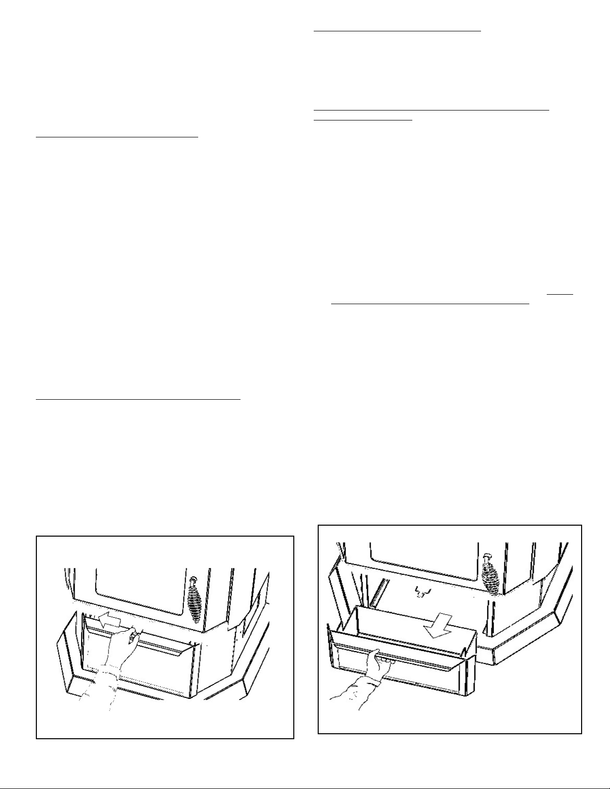
DISPOSAL OF ASHES
To dump ash from firebox, move lever to left several times
allowing spring to return against stop (Figure 15 & 16).
Once ash box is full, box should be placed in a non-
combustible floor or on the ground, well away from all
combustible materials pending final disposal. If the ashes
are disposed of by burial in soil or otherwise locally
dispersed, they should be retained in the closed container
until all cinders have been thoroughly cooled.
OPTIONAL 12V HOOK-UP & OPERATION
1. The EASYFIRE 12V back up can be purchased as an
option and includes the following components:
a. Deep cycle sealed 12V battery.
b. Battery connector cables for hook-up to the heater.
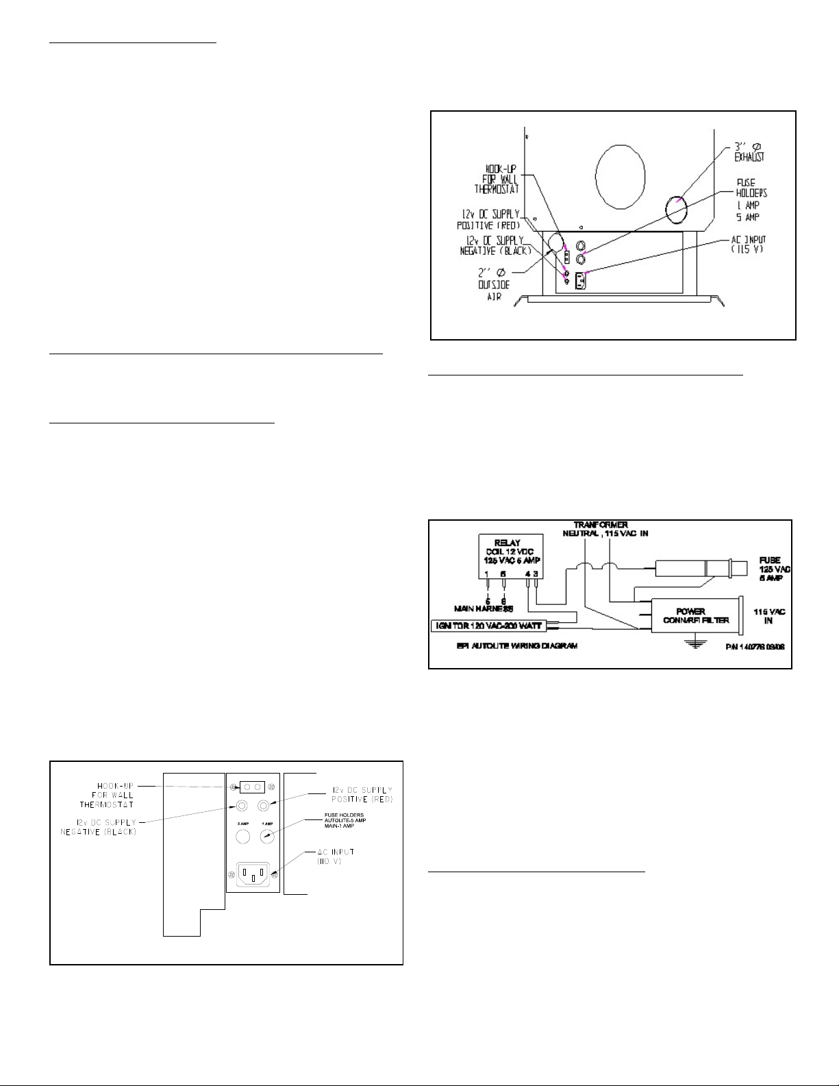
2. In order to hook-up the battery and engage the 12V
backup system simply connect red cable to red terminal
on the heater (see Figure 6) and to positive connector
on battery [the terminal marked (+)] and connect the
black cable to the black terminal on the heater and to
the negative connector on the battery (the terminal
marked (-). If you hook up the cables backwards the red
LED light above the terminal receptacles will come on. If
hooked up properly this LED will glow green.
WARNING - MAKE SURE RED CABLE GOES TO RED
TERMINAL (POSITIVE CONNECTOR) AND BLACK
CABLE GOES TO BLACK TERMINAL (NEGATIVE
CONNECTOR).
3. If you decide to purchase your own 12V back up system
we recommend a sealed gel cell battery. Failure to
install the proper battery could cause physical harm to
you and your property and will also void the heater
warranty.
4. When the battery is properly connected and the heater
plugged in, the following will happen automatically:
a. The heater will automatically switch to 12V power if
there is a power failure, and switch back when power
is restored.
b. The battery will be trickle charged as long as the
heater is plugged into 110 AC wall outlet. Do not use
extension cords. The trickle charge will not recharge
7