Eaton EFBWCV-REPEATER User manual

2
Technical Data PR216-219-508-01
Effective March 2017
Installation and user manual for the
BiWire / Conventional Repeater
Contents
Introduction ...........................................3
Purpose ............................................3
The BiWire / Conventional Repeater Panel ...................3
Indication Equipment (IE) ...............................3
Power Supply Equipment (PSE)..........................4
System Wiring .......................................5
Status Indications.....................................5
Repeater I/O.........................................7
Installation Instructions ..................................8
Before you begin .....................................8
Panel Installation .....................................9
Installation Testing ...................................14
Operating Instructions..................................15
Multi-Function Buttons................................15
Mute Buzzer........................................15
Lamp Test..........................................15
Technical Specification..................................16
Panel Specification ...................................16
PSE Specification ....................................16
Manufacturers Contact Details ...........................17
www.acornfiresecurity.com

3
Technical Data PR216-219-508-01
Effective March 2017
Installation and user manual for the
BiWire / Conventional Repeater
Introduction
Purpose
This manual is intended as a guide for the installation and commis-
sioning of the BiWire / Conventional Repeater panel. The content
of this guide is intended to assist the user to install a fire alarm
system and does not specify the detailed design of the product.
The guide assumes a reasonable level of competency with this
type of system.
The installation of this system can only be carried out by a compe-
tent person with relevant current training and experience, with
access to requisite tools, equipment and information (as stipulated
by BS5839).
The design has been carried out in accordance with a quality
management system, which incorporates a set of rules for the
design of all elements of the Indication Equipment (IE) and Power
Supply Equipment (PSE).
The components of the IE and PSE have been selected for the
intended purpose, and are expected to operate within their speci-
fication when the environmental conditions outside the cabinet of
the IE / PSE comply with class 3k5 of EN 60721-3-3:1995.
The BiWire/Conventional Repeater Panel
The BiWire/Conventional Repeater Panel mimics the visual and
audible indications of the Fire panel it is connected to. This is a
purely passive repeater panel so it is not possible to send instruc-
tions to the Fire panel to perform actions such as Sound Alarms,
Silence Alarms, or Reset. Each repeater panel comes with an
integral power supply and battery backup so there is no power
requirements from the main Fire panel.
Indication Equipment (IE)
The panel enclosure is constructed from PC ABS components.
The front cover is hinged at the bottom and is secured at the top
of the panel by two retaining screws. On the in-side of the panel a
sliding PCB tray makes it easy to remove the tray without touching
the PCB. The back box houses the PSE, the stand-by batteries and
has 29 x 20mm cable access points. Terminal blocks are positioned
to enable ease of connection. Figure 1 shows the dimensions of
the panel.
Figure 1. BiWire/Coventional Repeater Panel Dimensions
www.acornfiresecurity.com

4
Technical Data PR216-219-508-01
Effective March 2017
Installation and user manual for the
BiWire / Conventional Repeater
Power Supply Equipment (PSE)
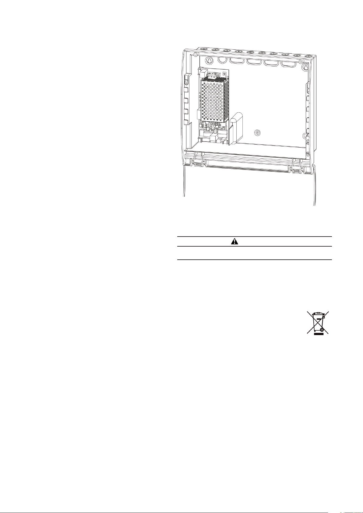
The PSE has been specifically designed to operate the panel and
may not be substituted for any other power source. The PSE is a
Switch Mode Power Supply located within the cabinet as shown
below. A dedicated 230V AC mains supply is required as the
primary source; the supply is fused on the PCB by a 10 amp anti-
surge fuse. In the event of mains failure the PSE will automatically
switched over to the standby battery power source until the main
power source is restored.
The PSE maintains the charge for the two 12V 5Ah sealed lead
acid batteries in a fully charged state. On initial power up the
batteries will charge over a 24 hour period. Dependent on the
charge of the installed battery the system may initially show a
charger or battery fault.
The supply should be clearly labelled ‘FIRE ALARM: DO NOT
SWITCH OFF’ at all isolation points.
PSE faults originating from the following are indicated by the panel
using a dedicated repeater power fault indicator:
• The loss of either power source
• Failure of the charger circuit
• High internal resistance of the battery
Figure 2 shows the location of the power supply. “PSE
Specification” on page 16 provides a full technical specification for
the power supply.
Note that the charging circuit will be in its high impedance state
(approximately 3V DC) if no batteries, faulty batteries, or only one
battery is connected. The full 27V DC (nominal) charging voltage
should be present if the correct batteries are connected.
In order to test for correct operation of the batteries, remove the
mains 230V AC fuse and allow the batteries to settle from their
charging voltage for approximately 5 minutes. The battery voltage
should then be measured using an electronic test meter and a
voltage greater than 24V DC should be present.
Figure 2. Power Supply Equipment
BATTERY DISPOSAL INSTRUCTIONS
WARNING
RISK OF EXPLOSION IF BATTERY IS REPLACED BY AN
INCORRECT TYPE
This product contains batteries and they must be disposed of in
accordance with current waste disposal and pollution legislation
and in particular The Environmental Protection Act 1990, Special
Waste Regulation 1996. It is recommended that the following
authorities are contacted before any attempt is made to dispose
of batteries; Environment Agency Local office, Local Authority
Environmental Health or Waste Handling department.
The batteries and fire panel comply with WEEE
disposal regulations. Do not dispose in general indus-
trial or household waste. Return unwanted products to
a designated collection point for waste electrical and
electronic equipment recycling.
www.acornfiresecurity.com

5
Technical Data PR216-219-508-01
Effective March 2017
Installation and user manual for the
BiWire / Conventional Repeater
System Wiring
As the repeater panel have integral power supplies the only wiring
that is required is the mains input to the power supply unit and
the data cable between the Fire Panel and each repeater panel as
illustrated in Figure 3.
Figure 3. System Wiring Diagram
Status Indications
Figure 4. Front Panel Status Indications
CIE REPEATER REPEATER REPEATER
RS485 RS485 RS485
RS485
www.acornfiresecurity.com

6
Technical Data PR216-219-508-01
Effective March 2017
Installation and user manual for the
BiWire / Conventional Repeater
Visual indications Audible
Indications
Condition
Power ON
General Fault
General Disablement
Repeater Fault/
System Fault
Battery Fault/
Mains Fault
Battery Failure/
Charger Fault
Sounder Fault/
Sounder Disablement
Self Test On /Test
Repeater Power Fault
FRE On
FRE Fault/
FRE Disablement
FPE Fault/
FPE Disablement
General Fire
Zone Fire (1-8)
Detector Removed /Zone
Fault/ Zone Disablement
Panel Buzzer
Comments
Fire Panel Indications (These mirror the current Fire Panel state)
Normal
Condition
OFF OFF OFF OFF OFF OFF OFF OFF OFF OFF OFF OFF OFF OFF Normal condition and at access
level 1
Access Level
2 or 3
FAST Access level 2 or 3 pass code
accepted
Fire Condition ON ON ON CONT Only the zone in fire will have its
zone fire indicator lit
System Fault ON ON SLOW Severe fault condition with the
Fire Panel
Repeater Fault ON SLOW SLOW Communication problem
between Fire panel and
repeater(s)
Battery Fault ON SLOW SLOW No battery voltage or battery
voltage too low
Mains Fault ON ON SLOW Mains voltage has been lost
Battery Failure ON SLOW SLOW Battery impedance fault
Charger Fault ON ON SLOW Charger voltage fault
Sounder Fault ON SLOW SLOW Short or open circuit condition on
the sounder circuit
FRE Fault ON SLOW SLOW Short or open circuit condition on
the FRE output
FPE Fault ON SLOW SLOW Short or open circuit condition on
the FPE output
Zone Fault ON SLOW SLOW Only the zone that has a short
or open circuit fault will have its
zone fault indicator slow flashing
Sounder
disabled
ON ON All fire alarm devices are disabled
FRE disabled ON ON FRE ouput disabled
FPE disabled ON ON FPE output disabled
Zone disabled ON ON Only the zone that is disabled
will have its zone fault indicator
lit
Repeater Panel Indications (Local to the repeater)
Normal
Condition
ON Normal condition and at access
level 1
Battery Fault ON ON No battery voltage or battery
voltage too low
Mains Fault ON ON Mains voltage has been lost
Battery Failure ON ON Battery impedance fault
Charger Fault ON ON Charger voltage fault
Communication
Fault
ON Communication lost with the
Fire Panel
KEY
ON (---------) Indicator lit
OFF Indicator unlit
SLOW ( - - - - ) Indicator slow flashing, buzzer slow pulsing
FAST ( - - - - - ) Indicator fast flashing, buzzer fast pulsing
SILENT Sounders off, buzzer off
CONT Sounders on, buzzers continuous
Any condition could be indicated
www.acornfiresecurity.com

7
Technical Data PR216-219-508-01
Effective March 2017
Installation and user manual for the
BiWire / Conventional Repeater
1 2
1 2
1 2
Repeater I/O
The Fire Panel provides a monitored RS485 bus that allows for up
to 3 passive repeater panels to be connected to it. The repeater
panels have their own power supplies so no power connection
is required from the Fire Panel. Each repeater panel must be
assigned a unique address using the DIP switches provided on the
repeaters.
When the Fire Panel is first powered up or after a hard reset it
will scan the RS485 bus for any repeaters connected. The panel
will briefly flash the Zone Fault indicators to show the number of
repeaters it has found. Below is a table of what these indications
mean.
It is important to note this during installation to ensure that the
panel has found the correct number of repeaters.
Once the repeaters have been found the Fire Panel will broadcast
all status information to them so that they will mirror the indicator
and buzzer states of the Fire Panel. The Fire Panel expects to
receive a response from each repeater, if at any time a repeater
stops responding for more than 60 seconds then the Fire Panel
will start to flash the “Repeater Fault” indicator.
Figure 5. Repeater Panel Connection
= 0 repeaters found
= 1 repeater found
= 2 repeaters found
= 3 repeaters found
1 2
www.acornfiresecurity.com

8
Technical Data PR216-219-508-01
Effective March 2017
Installation and user manual for the
BiWire / Conventional Repeater
Installation Instructions
This section of this guide explains in detail how the panel should
be installed and configured to function properly.
Please ensure you have fully understood the components of the
system and how they operate before proceeding with this section.
Take notice of the warnings and cautions as they are displayed for
your own safety and to prevent damage to your equipment.
Before you begin
WARNING
WHEN INSTALLING THE REPEATER PANELS CARE
SHOULD BE TAKEN TO ENSURE THAT THE INSTALLATION
LOCATION DOES NOT SUBJECT THE PANEL TO
ENVIRONMENTAL FACTORS IN EXCESS OF THE LIMITS
OUTLINED IN THE TECHNICAL SPECIFICATION CONTAINED
WITHIN THIS GUIDE.
CAUTION
ENSURE ANTI-STATIC PRECAUTIONS ARE TAKEN WHEN
HANDLING ELECTRONIC COMPONENTS OF THE SYSTEM.
DO NOT USE EXCESSIVE FORCE WHEN TIGHTENING THE
TERMINAL BLOCKS.
NOTE
INSTALLATION & MAINTENANCE MUST BE PERFORMED
BY AN APPROPRIATELY QUALIFIED PERSON.THE
EQUIPMENT CARRIES NO WARRANTY UNLESS THE
SYSTEM HAS BEEN INSTALLED AND COMMISSIONED
AND SUBSEQUENTLY MAINTAINED BY APPROPRIATELY
QUALIFIED PERSONS OR ORGANISATIONS. DO NOT
ATTEMPT TO INSTALL THIS EQUIPMENT UNTIL YOU
HAVE FULLY READ AND UNDERSTOOD THE OPERATION
AS DESCRIBED WITHIN THIS MANUAL, FAILURE TO DO
SO MAY RESULT IN DAMAGE TO THE EQUIPMENT AND
COULD INVALIDATE YOUR WARRANTY.
NOTE
WHEN INSTALLED THIS EQUIPMENT IS SUBJECT TO
THE EMC DIRECTIVE 2004/108/EC. TO MAINTAIN EMC
COMPLIANCE THE FIRE ALARM SYSTEM MUST BE
INSTALLED AS INSTRUCTED.THE INSTALLER WILL BE
RESPONSIBLE FOR ANY EMC PROBLEMS THAT MAY
OCCUR EITHER TO THE FIRE ALARM SYSTEM OR TO ANY
OTHER EQUIPMENT AFFECTED BY THE INSTALLATION IF
THERE IS ANY DEVIATION FROM THIS GUIDE.
NOTE
DIP SWITCH SETTINGS ONLY TAKE EFFECT ONCE THE
PANEL HAS BEEN POWER CYCLED OR THE HARD RESET
BUTTON IS PRESSED.
www.acornfiresecurity.com

9
Technical Data PR216-219-508-01
Effective March 2017
Installation and user manual for the
BiWire / Conventional Repeater
Panel Installation
NOTE
THE FOLLOWING INSTRUCTIONS MUST BE FOLLOWED
WITH MAINS AND BATTERY SUPPLIES DISCONNECTED
UNLESS OTHERWISE STATED.
NOTE
THE PANEL SHOULD BE INSTALLED IN A CLEAN, DRY,
REASONABLY WELL VENTILATED PLACE, AND NOT IN
DIRECT SUNLIGHT. TEMPERATURES IN EXCESS OF
40°C AND BELOW 5°C MAY CAUSE MALFUNCTIONS,
IF IN DOUBT CONSULT EATON ELECTRICAL SYSTEMS.
THE PANEL SHOULD BE LOCATED AWAY FROM ANY
POTENTIAL HAZARD, IN A POSITION WHERE IT IS
READILY ACCESSIBLE TO AUTHORISED STAFF, AND
THE FIRE SERVICES, IDEALLY ON THE PERIMETER OF A
BUILDING NEAR A PERMANENT ENTRANCE.
Mounting the Panel
To prepare the panel for mounting, you need to remove the front
cover of the panel, and the PCB shelf and the PSE from the back
box.
• To remove the front cover of the panel, unscrew the two retain-
ing screws located at the top corners of the panel, see Figure
15.
• It is recommended to remove the PCB shelf and the PSE from
the back box before drilling the holes.
• To remove the PCB shelf push the clips down ①, then push
the shelf towards the top of the back box and then lift forwards
②, see Figure 17.
• To remove the PSE PCB from the back box unplug the cables
from the main board as shown in Figure 17, then simply remove
the screw and push the PCB up, to the right and forwards as
shown in Figure 18.
Figure 6. Remove Panel front cover
Figure 7. Remove the PSE Shelf
Figure 8. Disconnect the PSE
Figure 9. Remove the PSE
www.acornfiresecurity.com

10
Technical Data PR216-219-508-01
Effective March 2017
Installation and user manual for the
BiWire / Conventional Repeater
• Once the cable entry holes have been cut then fit the cable
glands to the back box.
• If the panel is being flush mounted, then insert the panel into
the recess feeding the cables through the rear cable entry
points.
• If the panel is being wall mounted then cut out the required
number of cable entry holes in the back using a 20mm hole
saw with pilot drill bit as shown in Figure 19. Fit the glands to
the back box and pull through the required cables.
• Using the mounting holes in the back box, drill holes into the
wall and insert wall plugs and secure the panel to the wall as
shown in Figure 20. Ensure any dust is cleaned from the back
box.
• Secure the PSE PCB back into the back box by following the
reverse instructions in Figure 18.
• Fit the PCB shelf and cables by following the reverse instruc-
tions in Figure 16 and Figure 17 on page 9.
• If the panel is wall mounted, pull the cabling through the glands
ready for wiring.
• Fit the door back onto the back box by following the reverse
instructions in Figure 15.
Figure 10. Cut cable entry holes
Figure 11. Secure the panel to the wall
www.acornfiresecurity.com

11
Technical Data PR216-219-508-01
Effective March 2017
Installation and user manual for the
BiWire / Conventional Repeater
Connecting the Mains Supply
The mains supply should be exclusive to the fire alarm as detailed
in BS5839. A plug and socket is not satisfactory.
We recommend that a switched double pole fused spur unit is
used for the sole use of the fire alarm system and should be
clearly marked with:
FIRE ALARM DO NOT SWITCH OFF
Before connecting the fused spur to the PSE, slide the ferrite core
(supplied with the panel) over the cable as shown in Figure 21.
Connect the fused spur to the input marked MAINS on the PSE,
observing correct wiring regulations.
NOTES
OBEY VOLT DROP LIMITATION WHEN SIZING CABLES.
USE ONLY APPROVED CABLE TYPES.
DO NOT TIGHTEN TERMINAL CONNECTOR SCREWS TOO
TIGHT.
KEEP POLARITY THROUGHOUT. NON COLOURED
CONDUCTORS SHOULD BE PERMANENTLY MARKED.
Figure 12. Mains Supply connection to PSE
Connecting the Battery Supply
A Battery cover is supplied to prevent accidental contact with
the battery terminals and gives additional useful information. The
battery cover can be moved out of the way as indicated in Figure
22.
Connect the spade connectors of the two wire battery cable and
the single wire battery cable as illustrated in Figure 21
Do not connect the plastic socket end of the battery cable to the
PSE until all installation actions in this guide have been completed
and the system is ready for testing.
Figure 13. Battery cover removal
www.acornfiresecurity.com

12
Technical Data PR216-219-508-01
Effective March 2017
Installation and user manual for the
BiWire / Conventional Repeater
Battery Connections
1. Connect the BLACK battery wire to the BLACK (-) battery
terminal of Battery B (Figure 23)
2. Connect the RED battery wire to the RED (+) battery
terminal of Battery A (shown as grey)
3. Connect the link cable between the two remaining
terminals
CAUTION
DO NOT USE A HIGH VOLTAGE TESTER WHEN WIRING IS
CONNECTED TO ANY ELECTRONIC EQUIPMENT.
NOTE
IT IS IMPORTANT THAT ZONE CABLING IS CONNECTED
TO THE CORRECT ZONE INPUT OTHERWISE ANY FIRE OR
FAULT INDICATION ON THE PANEL WILL NOT MATCH THE
ZONE MAP OF THE SITE, AND WILL NOT BE COMPLIANT
WITH BS5839
Figure 14. Battery Connection
Figure 15. Repeater Panel Wiring Diagram
www.acornfiresecurity.com

13
Technical Data PR216-219-508-01
Effective March 2017
Installation and user manual for the
BiWire / Conventional Repeater
Connecting a Repeater Panel
If a single Repeater panel is being connected to the Fire Panel
then simply connect one end of the twisted pair cable to the
Repeater I/O terminals on the Fire Panel and the other end of the
cable to the Repeater I/O terminals on the Repeater Panel (see
Figure 15), observing correct polarity (+ to +., - to -).
When daisy chaining repeater panels together simply connect
another twisted pair cable between each Repeater I/O terminals.
This will mean that some of the terminals will have 2 cables
connected to it.
Once all the repeaters are wired together each repeater panel
needs to be assigned a unique address from 1 to 3 DIP switch 12
as shown below.
Figure 16. Interlink wiring diagram
www.acornfiresecurity.com

14
Technical Data PR216-219-508-01
Effective March 2017
Installation and user manual for the
BiWire / Conventional Repeater
Installation Testing
Initial Power-up Check
Power up the panel by engaging the fuse spur to supply mains,
then connect the white socket of the battery cable to the power
supply (see Figure 24 on page 16).
Check that all indicators turn on in turn momentarily and turn off
again.
Only the power on indicator should be lit afterwards.
Any fault indications should be investigated and corrective actions
taken before continuing with the installation tests. “Status
Indications” on page 8 provides a comprehensive guide to
the fault indications.
Power off the panel before commencing any corrective action on
the panel.
WARNING
DO NOT FIX ANY FAULT CONDITIONS WITH THE SYSTEM
STILL POWERED UP. THIS IS PARTICULARLY IMPORTANT
WITH SHORT CIRCUIT FAULTS ON ZONES AS THE PTC
FUSE NEEDS TIME TO RECOVER IF IT HAS TRIPPED.
Repeater Check
• Place an individual zone into Zone Test Mode on the Fire
Panel (see Fire Panel manual for further instructions on how
to put it into Zone Test mode). Check the following on the
repeater panel:
• Self-Test On indicator is slow flashing
• Buzzer is slow beeping
• Activate a call point that in the zone in test mode and then
check the following on the repeater panel:
• Self-test On indicator is slow flashing
• General Fire indicator is on
• Correct zone fire indicator is on
• Buzzer is continuous
• Take the Zone out of Test Mode at the Fire Panel and reset
the system. All indications on the repeater should mirror
those on the Fire Panel.
Battery Fault Detection Check
Disconnect the battery of the repeater panel.
After about 20 seconds check the Repeater Power Fault indicator
is on.
Re-connect the battery of the repeater panel.
After about 4 seconds check the Repeater Power Fault indicator is
off.
www.acornfiresecurity.com

15
Technical Data PR216-219-508-01
Effective March 2017
Installation and user manual for the
BiWire / Conventional Repeater
Operating Instructions
Multi-Function Buttons
The numerical value in the centre of the button is used to enter
access codes for level 2.
Mute Buzzer
This function is available at access level 1 and 2.
• To silence the panel’s internal buzzer at access level 1 just press
the Mute Buzzer button.
• To silence the panel’s internal buzzer at access level 2 enter the
code 3112 and then press the Mute Buzzer button.
• This will only silence the buzzer of the repeater and not the Fire
Panel
This function will immediately exit back to Access Level 1.
Lamp Test
This function is available at access level 2.
• Enter the access code 3112.
• Press Indicator Test button ③.
• Each indicator on the front of the panel will turn on in turn and
then turn off in turn (excluding the Power On indicator).
This function will immediately exit back to Access Level 1.
www.acornfiresecurity.com

16
Technical Data PR216-219-508-01
Effective March 2017
Installation and user manual for the
BiWire / Conventional Repeater
Technical Specification
Panel Specification
EFBWCV-REPEATER
Power Specification
Input Voltage Range 18.75-30.7V DC
Maximum current drawn from battery 2.7A
Communication Ports
Repeater Port Type RS485
Nodes Up to 3 repeaters and a fire panel
Note: The use of this port is outside the scope of EN54 certification
Environmental
Operating Temperature °C-5°C to +40°C
Relative Humidity %93% +/3% non-condensing
IP Rating IP30
Mechanical
Dimensions mm 375 (W) x 366 (H) x 134 (D)
Weight kg 2.25
Material PC ABS Front and Rear
Cabling
Cable Access 29 x 20mm drill positions - Slots for rear cable entry
Cable Type Cable type 2 core 1.5mm, 2 screened fire rated cable (twisted pair)
500m (max)
Compliance
Compliance to Standards BS5839, part1
PSE Specification
EFBWCV-REPEATER
Power Specification
Mains Voltage 230V AC -10% / +15%, 50Hz
Mains Fuse 1 Amp Anti-Surge
Battery Details
Number of Batteries 2
Capacity 12V, 5Ah
Recommended Battery Yucell Y5 -12 (Yuasa)
Battery Fuse 6.3A Anti-Surge
Battery voltage (Charging
value)
27.3V DC @20%
Recommended period for
battery replacement
5 years
PSE Ratings
Ouptut voltage 18.75-30.7V DC
Maximum ripple voltage 425mV rms (1.2Vp-p)
Imin 39mA
Ri max 1Ω
PSE Fault Options
Mains OK (J4 pin 4) >=3V Mains present, <=3V Mains fault
Fault_Charger (J4 pin 1) >=3V for 1s pulsed at 0.2Hz Charger OK
>=3V for 1s pulsed at 1Hz Charger fault
Steady high/low (no pulsing) PSE Micro fault
Fault_Battery (J4 pin 3) =0.17* (Vbat-0.6) Volts
0V (J4 pins 2 and 10) reference
www.acornfiresecurity.com
Table of contents
Popular Repeater manuals by other brands

industrie technik
industrie technik MRPW instruction manual

U-Prox
U-Prox HW Installation and programming manual

Sepura
Sepura SER8010 Installation and operation guide

KMC Controls
KMC Controls KMD-5575 Installation and operation guide

SmarTrunk Systems
SmarTrunk Systems ST-9116C Service manual

Eletech
Eletech EM3028B user manual