EAW RS121 User manual

RS Series User Manual

1
IMPORTANT SAFETY INSTRUCTIONS - READ THIS FIRST
Safety Instructions
Read and heed all warnings and safety instructions in this manual before using this product. Failure to
follow these precautions may result in damage, injury, or death.
1) Read these instructions.
2) Keep these instructions.
3) Heed all warnings.
4) Follow all instructions.
5) Do not use this apparatus near water.
6) Clean only with a dry cloth.
7) Do not block any amplifier ventilation openings. Install in accordance with the manufacturer's
instructions.
8) Do not install near any heat sources such as radiators, heat registers, stoves, or other apparatus
that produce heat.
9) Do not defeat the safety purpose of the polarized or grounding-type plug. A polarized plug has
two blades with one wider than the other. A grounding type plug has two blades and a third
grounding prong. The wide blade or the third prong is provided for your safety. If the provided
plug does not fit into your outlet, consult an electrician for replacement of the obsolete outlet.
10) Protect the power cord from being walked on or pinched particularly at plugs, convenience
receptacles and the point where they exit from the apparatus.
11) Only use attachments/accessories specified by the manufacturer.
12) Use only with the Caster Pallets and accessories specified by the manufacturer or sold with the
apparatus. When a Caster Pallet is used, use caution when moving the apparatus combination
to avoid injury from tip-over.
13) Unplug this apparatus during lightning storms or when unused for long periods of time.
14) Refer all servicing to qualified service personnel. Servicing is required when the apparatus has
been damaged in any way, such as power-supply cord or plug is damaged, liquid has been

2
spilled or objects have fallen into the apparatus, does not operate normally, or has been
dropped.
15) DO NOT ATTEMPT TO OPEN THE AMPLIFIER ITSELF; IT IS NOT USER-SERVICEABLE.
i. WARNING:The loudspeaker is supplied with an AC mains power cable. Depending on the
voltage model ordered, this cable is configured with the most common ac mains connector
for that voltage. If the connector is not compatible with the local ac mains receptacle,
employ a licensed electrician to re-configure the cable with the proper connector. Ensure
that ac power supply has a properly grounded safety ground. Failure to follow this warning
could cause equipment damage, injury, or death.
FCC Compliance
This equipment has been tested and found to comply with the limits for a Class A digital device, pursuant to
Part 15 of the FCC Rules (pending). These limits are designed to provide reasonable protection against harmful
interference when the equipment is operated in a commercial environment. This equipment generates, uses,
and can radiate radio frequency energy and, if not installed and used in accordance with the instruction manual,
may cause harmful interference to radio communications. Operation of this equipment in a residential area is
likely to cause harmful interference in which case the user will be required to correct the interference at his own
expense.
CAUTION: Changes or modifications not expressly approved by EAW could void the user's authority to operate
the equipment.
The normal function of the product may be disturbed by Strong Electro Magnetic Interference. If so, simply reset
the product to resume normal operation by following this instruction manual. If the product does not resume
normal operation, please use the product in another location.
WARNING: Operation of this product in a residential environment could cause radio interference.
Correct Disposal of this Product
This symbol indicates that this product should not be disposed of with your household
waste, according to the WEEE Directive (2002/96/EC) and your national law. This product
should be handed over to an authorized collection site for recycling waste electrical and
electronic equipment (WEEE). Improper handling of this type of waste could have a
possible negative impact on the environment and human health due to potentially
hazardous substances that are generally associated with WEEE. At the same time, your
cooperation in the correct disposal of this product will contribute to the effective usage
of natural resources. For more information about where you can drop off your waste equipment for recycling,
please contact your local city office, waste authority, or your household waste disposal service.

3
Table of Contents
IMPORTANT SAFETY INSTRUCTIONS - READ THIS FIRST ............................................................................................1
FCC Compliance..........................................................................................................................................................2
Correct Disposal of this Product.................................................................................................................................2
RS™ System Overview ................................................................................................................................................5
RS Two-Way Point Source ..................................................................................................................................5
RS Subwoofers....................................................................................................................................................6
Unpacking ...................................................................................................................................................................7
Contents .....................................................................................................................................................................7
Functions and Operations ..........................................................................................................................................8
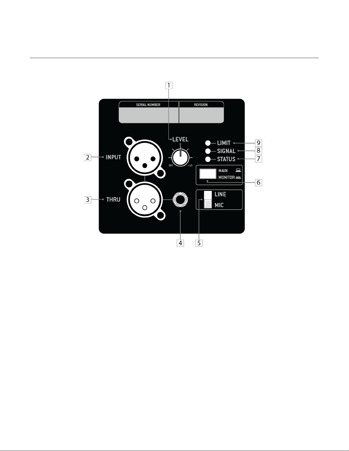
RS 121, 123, 151, 153 Rear Input Panel Diagram...............................................................................................8
RS115 Rear Input Panel Diagram..................................................................................................................... 10
RS118 Rear Input Panel Diagram..................................................................................................................... 12
Audio Connections .................................................................................................................................................. 13
Analog Audio ................................................................................................................................................... 13
AC Mains Connection .............................................................................................................................................. 14
Linking power (only on RS 123/153 Models)................................................................................................... 14
Operating Indicators................................................................................................................................................ 15
Operating Limits .................................................................................................................................................. 15
Adjusting the Output Level.................................................................................................................................. 16
Onboard Processing & Voicing ................................................................................................................................ 16
Voicing Options................................................................................................................................................ 16
Main................................................................................................................................................................. 16
Monitor............................................................................................................................................................ 16
EAW DSP Innovations.............................................................................................................................................. 17
DynO™ ............................................................................................................................................................. 17
EAW Focusing™ ............................................................................................................................................... 17
RS Application Configurations ................................................................................................................................. 18
Rotating the horn ............................................................................................................................................ 18
Application Notes .................................................................................................................................................... 19
Flying RS from threaded mounting points .......................................................................................................... 19
Using RS as a Stage Monitor................................................................................................................................ 19

4
Using Pole Mount with RS (on tripod or RS subwoofer) ..................................................................................... 19
Rigging ..................................................................................................................................................................... 20
Basic Field Troubleshooting & Repair...................................................................................................................... 21
Rigging Problems ................................................................................................................................................. 22
Enclosure and Integral Hardware........................................................................................................................ 22
Cosmetics............................................................................................................................................................. 22
Driver Service....................................................................................................................................................... 22
Powered Loudspeaker Electronics ...................................................................................................................... 23
Internal Electronics and Wiring ........................................................................................................................... 23
Electrical Warnings .................................................................................................................................................. 23
AC MAINS SUPPLY ............................................................................................................................................... 23
Operating Temperature....................................................................................................................................... 23
General Service.................................................................................................................................................... 24
Rigging Service..................................................................................................................................................... 24
Routine Maintenance .......................................................................................................................................... 24
Internal Electronics and Wiring ........................................................................................................................... 24
Contacting EAW....................................................................................................................................................... 25
Operating Questions ........................................................................................................................................... 25
Service Information ............................................................................................................................................. 25

5
RS™ System Overview
RS is the newest powered point‐source loudspeaker from EAW. Drawing from EAW’s rooted legacy as a
manufacturer of high‐end touring loudspeakers, RS is designed specifically for the professional audio users in
corporate AV, rental & staging, and installation. RS Series consists of four two-way, point source models (RS121,
RS123, RS151, & RS153) and two subwoofers (RS115 & RS118).
SPECIFICATIONS
RS Two-Way Point Source

6
RS Subwoofers

7
Unpacking
You should have visually inspected the outside of the shipping carton and noted any damage on the shipping
bill you signed. After unpacking, if you find concealed damage to the loudspeaker, save the packing materials
for the carrier's inspection, notify the carrier immediately and file a shipping damage claim.
Although EAW will help in any way possible, it is always the responsibility of the receiving party to file any shipping
damage claim. The carrier will help prepare and file this claim.
Contents
Qty
Item
1
RS Series Product
1
Power Cables
•RS Models 121/151: IEC to Edison
•RS Models 123/153: Powercon to Edison
1
Warranty Card

8
Functions and Operations
RS 121, 123, 151, 153 Rear Input Panel Diagram
1. Level (Gain) Control
Adjusts the level of the INPUT signal. Turning counterclockwise will reduce the output level and
turning clockwise will raise the overall output level of the speaker.
2. XLR Input Connector
Balanced XLR input connector for analog input signal.
3. XLR Thru (Output) Connector
Balanced XLR output connector to daisy-chain input signal to other speakers. This signal comes
directly from the input signal and is unaltered by speaker’s internal processing.
4. Balanced TRS Connector
Balanced 1/4” TRS input connector for analog input signal.
5. Line/Mic Switch
This switch controls the input sensitivity. For low-voltage signals, such as from a microphone, set the
switch to the MIC position. For high-voltage signals, such as from a mixing console, set the switch to
the LINE position.
NOTE: Utilizing the MIC switch position with a high-voltage signal may cause damage to your speaker –
be sure to use the proper switch settings based on the incoming signal strength.

9
6. Main/Monitor Button
This button is used to toggle between the speaker’s two pre-defined voicings – MAIN and MONITOR.
The MAIN voicing should be chosen when the speaker is placed on a tripod or installed. The MONITOR
voicing should be chosen when the speaker is placed on the floor or at its monitor angle – this setting
reduces the impact of low frequency floor coupling that occurs when a speaker is placed on the floor,
providing a cleaner and more coherent output.
7. Status LED Indicator
The status indicator will remain lit if the speaker is in functioning condition. If the light blinks, it
indicates that the speaker has entered temperature protection mode and must be cooled down and
power-cycled before it will function normally.
8. Signal LED Indicator
The status indicator will turn green when an input signal is detected. NOTE: Low-voltage signals may
not be able strong enough to trigger the LED indicator, but may still be heard from the speaker – this
is perfectly fine.
9. Limit LED Indicator
The limit indicator will turn red when the output has reached its maximum level. If the LED blinks
occasionally, EAW DynO™ will optimize the output and continue to provide clear output at its
maximum volume. If the LED blinks frequently or is lit continuously, reduce the level control (1) to
prevent output distortion.
NOTE: Only one signal input may be used at a time (2 or 4) – using both at the same time will result in a
distorted signal.

10
RS115 Rear Input Panel Diagram
1. Level (Gain) Control
Adjusts the level of the INPUT signal. Turning counterclockwise will reduce the output level and
turning clockwise will raise the overall output level of the speaker.
2. XLR Input Connector
Two balanced XLR input connectors for analog input signal.
3. XLR Thru/Xover (Output) Connector
Two balanced XLR output connector to daisy-chain input signal to other speakers. This signal can
either come directly from the input connector (unaltered by the speaker’s internal processing), or
high-passed at the XOVER frequency based on the position of the OUTPUT button (4).
4. Output Button
This button is used to toggle the processing of the XLR THRU/XOVER output signal. Setting the button
to THRU outputs a signal unaltered by the speaker’s internal processing, whereas setting the button to
XOVER applies a high-pass filter to the output signal at the frequency determined by the XOVER
button position (5). The button should be set to the THRU position if daisy-chaining to other
subwoofers, or if connecting a full-range speaker that utilizes an external high-pass filter. The button
should be set to XOVER if outputting directly to RS two-way speakers or if the connected full-range
speaker does not have an integrated high-pass filter option.

11
5. Crossover Button
This button is used to toggle between crossover frequencies – the two crossover frequency options
are 80Hz and 100Hz.
6. Mode Button
This button is used to toggle between the speaker’s two pre-defined voicings – Normal and Depth.
Though normal mode is tuned for deep, robust bass, depth focuses on further boosting frequencies
on the lower end of its frequency range.
7. Status LED Indicator
The status indicator will remain lit if the speaker is in functioning condition. If the light blinks, it
indicates that the speaker has entered temperature protection mode and must be cooled down and
power-cycled before it will function normally.
8. Signal LED Indicator
The status indicator will turn green when an input signal is detected. NOTE: Low-voltage signals may
not be able strong enough to trigger the LED indicator, but may still be heard from the speaker – this
is perfectly fine.
9. Limit LED Indicator
The limit indicator will turn red when the output has reached its maximum level. If the LED blinks
occasionally, EAW DynO™ will optimize the output and continue to provide clear output at its
maximum volume. If the LED blinks frequently or is lit continuously, reduce the level control (1) to
prevent output distortion.

12
RS118 Rear Input Panel Diagram
1. Level (Gain) Control
Adjusts the level of the INPUT signal. Turning counterclockwise will reduce the output level and
turning clockwise will raise the overall output level of the speaker.
2. XLR Input Connector
Two balanced XLR input connectors for analog input signal.
3. XLR Thru/Xover (Output) Connector
Two balanced XLR output connector to daisy-chain input signal to other speakers. This signal can
either come directly from the input connector (unaltered by the speaker’s internal processing), or
high-passed at the XOVER frequency based on the position of the OUTPUT button (4).
4. Output Button
This button is used to toggle the processing of the XLR THRU/XOVER output signal. Setting the button
to THRU outputs a signal unaltered by the speaker’s internal processing, whereas setting the button to
XOVER applies a high-pass filter to the output signal at the frequency determined by the XOVER
button position (5). The button should be set to the THRU position if daisy-chaining to other
subwoofers, or if connecting a full-range speaker that utilizes an external high-pass filter. The button
should be set to XOVER if outputting directly to RS two-way speakers or if the connected full-range
speaker does not have an integrated high-pass filter option.
5. Crossover Button
This button is used to toggle between crossover frequencies – the two crossover frequency options
are 80Hz and 100Hz.

13
6. Mode Button
This button is used to toggle between the speaker’s two pre-defined voicings – Normal and Punch.
Normal mode is tuned for deep, robust bass, whereas punch focuses on boosting frequencies on the
upper-end of its frequency range, adding extra power to kick drums.
7. Status LED Indicator
The status indicator will remain lit if the speaker is in functioning condition. If the light blinks, it
indicates that the speaker has entered temperature protection mode and must be cooled down and
power-cycled before it will function normally.
8. Signal LED Indicator
The status indicator will turn green when an input signal is detected. NOTE: Low-voltage signals may
not be able strong enough to trigger the LED indicator, but may still be heard from the speaker – this
is perfectly fine.
9. Limit LED Indicator
The limit indicator will turn red when the output has reached its maximum level. If the LED blinks
occasionally, EAW DynO™ will optimize the output and continue to provide clear output at its
maximum volume. If the LED blinks frequently or is lit continuously, reduce the level control (1) to
prevent output distortion.
Audio Connections
Analog Audio
Connect the output from your line-level signal source to either the XLR-3F INPUT or TRS connector on the
rear panel. These are electronically balanced inputs. Only one of these connectors can be connected at a
time – using both inputs at the same time will cause input distortion. Users must provide their own XLR/TRS
cables. The two XLR-type connectors (one female and one male) and TRS connector on the rear of each RS
series product are designed for professional audio signal levels, nominally 0 dB (= 0.775 V). Normally, use
the female XLR or TRS as the signal input. Use the male XLR as a loop-thru output to connect the same signal
input to additional RS products.
The XLR wiring convention is as
follows:
Pin 1: Shield
Pin 2: +/Hot
Pin 3: -/Cold

14
The TRS wiring convention is as follows:
Pin 1: Shield
Pin 2: +/Hot
Pin 3: -/Cold
AC Mains Connection
Connect the supplied AC mains cord to the IEC connector (RS 121/151 Models) or Neutrik® powerCON® socket
(RS 123/153 Models) on the rear of the loudspeaker. Connect the other end to an AC mains supply receptacle,
nominally 115V 60Hz or 230V 50 Hz as labeled on the loudspeaker. If necessary, have a qualified electrician
change the cable plug as required for compatibility with the local AC mains receptacle.
WARNING:Before connecting an RS loudspeaker to the AC mains supply, completely turn down the input signal to
the loudspeaker using the input level attenuator. Failing to do say may result in excessive and possibly damaging
sound pressure levels emanating from the loudspeaker when powered.
Linking power (only on RS 123/153 Models)
The Neutrik® powerCON® AC mains and AC loop connectors are
wired in parallel to provide an AC mains inlet and outlet on each
RS product. The blue AC mains inlet mates with a Neutrik®
powerCON® NACFC3A (supplied). The white AC mains outlet
mates with a Neutrik® powerCON® NACFC3B. Therefore, to loop
the AC mains from enclosure to enclosure, connect an AC mains
jumper cable as shown (jumper is not included with RS series
products).
Up to four additional RS 123/153 products can be looped in this
fashion. Use an AC loop connector to daisy-chain AC mains power from one enclosure to another. The
maximum, continuous load must not exceed 12A for the 115V version and 6A for the 230V version.
NOTE: The circuit breaker only protects the AC loop outlet, not the AC mains connector. If the continuous load
connected to the AC loop outlet exceeds the rated load, the circuit breaker will trip. For this situation, reduce the
connected load and then manually reset the circuit breaker.

15
Operating Indicators
Please refer to the chart below to determine the current operating status based on the three LED indicators
located on the rear-input panel of your RS unit.
Indication
Condition Next Steps
LED
Color/Repeat
Period
Status LED Green - Solid
All
components
working
properly
None
Signal LED Green -
Flashing/Solid
An input
signal is being
received by
the amplifier.
None
Limiter LED
Red - Flashing The speaker is
soft limiting. None
Red - Solid The speaker is
clipping.
Reduce volume until
the limit light only
flashes occasionally.
ALL LEDs Flashing System Fault Contact EAW
Support.
Limit
The limiting parameters set in RS Products are engineered to provide a high level of protection for the drivers
while maximizing sonic performance and output. The Limit indicator in the rear input panel illuminates when
limiting is occurring. If this is flashing occasionally, meaning no more than once every 3 seconds or so, then
levels are probably OK, but at maximum if this indicator is flashing more than once every 3 seconds or so,
reduce the input signal level.
CAUTION: Electronic limiters cannot provide absolute protection against driver failure. Thus, if limiting is occurring,
it is a warning that excessive signal levels are being approached. EAW is not responsible for damaged or broken
speaker components due to user error.
Operating Limits
The RS products have a Limiter indicator. The speaker is designed to maximize performance and clarity at
limit – if the limit light is blinking every few seconds, no action is needed. If the limit light is flashing more
frequently, or is continuously on, reduce the volume to avoid distortion.

16
Adjusting the Output Level
Starting with the input level attenuator at -∞ (all the way to the left), turn the input attenuator up until
the desired volume is reached, but below the point where the Limiter light illuminates.
Onboard Processing & Voicing
Voicing Options
RS features two distinct voicings on two-way to accommodate select applications. To select voicings, simply
press the ‘Mode’ button on the back panel until the button position is identical to that of the desired voicing
position depicted to the right of the button.
Main
Select the ‘Main’ voicing when using RS speakers on a tripod or hung for installation.
Monitor
Select the ‘Monitor’ voicing when using the speaker as a floor wedge monitor. It’s designed to reduce floor
coupling of low frequencies, providing a clean and accurate bass response.

17
EAW DSP Innovations
DynO™
DynO™ is a revolutionary processing technique that allows
EAW Engineers to maximize output from a given amplifier
– transducer combination. As opposed to conventional
limiting which simply views amplifier output and driver
power handling in aggregate (i.e. a driver can handle 100
watts or an amplifier can produce 500 watts), the DynO
process involves much more detail and complexity. By
studying the headroom of all electronic and acoustical
devices frequency by frequency and utilizing frequency‐
dependent limiting algorithms in combination with more traditional band-pass limiting, a system’s
broadband headroom can be maximized regardless of the input signal spectrum.
EAW Focusing™
Even in well-designed professional loudspeakers, inherent sonic
flaws such as phase plug reflections, horn resonances and cone
resonances can cause undesirable audible artifacts. Implemented
through advanced digital signal processing, EAW Focusing™
generates complex filters that correct these imperfections and
improve the transient response of a loudspeaker. This is
accomplished by isolating linear, time invariant and spatially
consistent anomalies in a loudspeaker’s response and eliminating
them through advanced processing. The result is a high output,
controlled loudspeaker that provides a pristine transient response
equal to that of a direct radiating studio monitor.

18
RS Application Configurations
Rotating the horn
RS products feature a user-rotatable horn, providing exceptional application flexibility and the ability to
maintain the 90ox 60ocoverage pattern when the speaker is mounted horizontally. To rotate the horn,
please follow the steps outlined below.
1. Remove the retaining screws securing the grill in place using a standard Philips head screwdriver.
2. Remove the HF horn assembly by unscrewing their retaining screws using standard Philips head
screwdriver.
3. Carefully lift the HF horn/driver assembly from the baffle
4. Rotate the HF horn/driver assembly 90 degrees. *
5. Replace the HF horn/driver assembly back into the enclosure and
re-fasten the retaining screws
6. Replace the grille and re-fasten the retaining screws.
The horn diagram on the left denotes the horn in its original 90° x 60° (HxV) coverage pattern, whereas the horn diagram on the right denotes
the horn in its 60° x 90° (HxV) coverage pattern.
The horn orientation can be determined by the labelling of the horn edge. The horizontal writing
denotes the corresponding horizontal dispersion angle, and the vertical writing denotes the
corresponding vertical dispersion angle. The orientation of the horn can also be determined by the

19
orientation of the horn throat opening. When the opening is in the vertical orientation, the horn is in
the default 90ox 60oconfiguration. If the opening is horizontal, the horn is in the 60ohorizontal x 90o
vertical orientation.
Application Notes
Flying RS from threaded mounting points
RS products attachment points are designed to accept M10 hardware. Always use a
minimum of two points to suspend any loudspeaker.See section on “Rigging” later
in this manual for more information.
Using RS as a Stage Monitor
RS loudspeakers are designed to be placed on their side and used as
a stage monitor. To change to the correct voicing, main/monitor
button should be pressed in when in use as a floor monitor.
Using Pole Mount with RS (on tripod or RS subwoofer)
RS loudspeakers have a 35mm pole cups located on the bottom of the speaker. This
can be used to deploy the loudspeakers on either a tripod stand or on top of a
subwoofer using an M20-threaded pole as seen below.
This manual suits for next models
3
Table of contents
Other EAW Speakers manuals