ECB E10.14000.45 L-EUF User manual

Operation Manual
for the authorized specialist
Dual-fuel Burner
E 10... L-EUF
06/2006 102.885.8162

2
Inhalt
Overview Important Information Warranty Product Description .......................................... 3
Technische Daten ................................................................................................. 4
Dimensioned Drawings ......................................................................................... 5
Start-up Mode Oil Operating Mode General Safety Functions .............................. 6
Fuel-air Compound Control ................................................................................... 7
Hydraulic diagram L-E... / GL-E... Burner E 10 ..................................................... 8
Hydraulic Valves and Instruments Group .............................................................. 9
Start-up Burner Head Settings .......................................................................................... 10
Installation Mounting to Boiler Electrical Connection Presetting ........................................... 11
Boiler Lining ........................................................................................................ 12
Burner GL/L-EUF ................................................................................................ 12
Oil Connection Oil Pressure Control (Feed) ........................................................ 13
Nozzle rod linkage 32 - EH ................................................................................. 14
Start-up Return Nozzle Rod RDG 1250 ............................................................................ 17
Nozzle selection „Sonic“ ...................................................................................... 18
Checking Procedure ............................................................................................ 19
Adjusting Instructions Air Flow Rate Adjusting Procedure ..................................................................... 20
Elektronic Burner Control with Electronic Compound Controller ......................... 21
Flame Detecting System Type FLW 05 .............................................................. 22
Servomotor Type SAD 15.0 ................................................................................ 23
Electrical Actuator STM 40 .................................................................................. 24
Starting the BCS, Etamatic, VMS/FMS Electronic Compound Controller ........... 25
Adjusting Instructions Oil Pressure Switch Air Pressure Switch ........................................................... 26
Overview Flame monitor ..................................................................................................... 27
Flame monitor ..................................................................................................... 28
Fan Impeller ........................................................................................................ 32
Service Instructions Maintenance Burner ............................................................................................ 33
Exhaust Gas Test ................................................................................................ 35
Trouble Shooting Instructions ............................................................................. 36
Operating Trouble ............................................................................................... 38
System Diagram .................................................................................................. 39
Product description Brenner E10.12000/14000 L-EUF ....................................................................... 40
Overview

3
Overview
Important Information
Warranty
Product Description
Important information
The burners of type E 10... L-EUF have
been designed for the combustion of
heavy fuel oil. The burners should be
installed and taken into operation care-
fully by qualified personnel. The work
should be done in accordance with the
applicable regulations and guidelines.
Only a duly authorized specialist should
be entrusted with the installation of the
gas system.
Any repair work on monitors, limiters
and automatic furnace controllers and
on the other safety facilities are allowed
to be done on the single items only by
the manufacturers themselves or spe-
cialists authorized by them.
Original parts should only be exchan-
ged by a duly qualified specialist.
Standards and regulations
The following standards should be
observed in the interest of a safe, easy-
on-the-environment and energy-saving
operation of the burner:
EN267/
DIN4787
Oil Atomizing Bur-
ners
VDE 0116 Electrical Equipment
of Furnaces
According to DIN 4755 the user must be
instructed in the operation of the fur-
nace system.
For the installation of an oil furnace sys-
tem, care should be taken to observe
DIN 4755, TRbF (Technical Regulation
on Combustible Liquids) and the local
furnace construction regulations appli-
cable in the country.
Place of installation
The burner must not be operated in
rooms containing corrosive vapours
(e.g. spray, perchloroethylene, hydro-
carbon tetrachloride, solvent, etc.) and
tending to heavy dust formation and
only up to 60% relativ air humidity.
Adequate ventilation must be provided
at the place of installation of the furnace
system to ensure a reliable supply with
combustion air.
Maintenance
The furnace system should be serviced
at least once a year by an authorized
specialist. It is recommended to con-
clude a maintenance agreement to this
effect.
Warranty
Manufacturer will not accept any war-
ranty if the operating instructions have
not been duly observed in the start-up
and maintenance of the burner and
damages have been caused by impro-
per installation, incorrect adjustment,
unauthorized interference or operating
errors.
Product description
The burners of type E10...L-EUF have
been designed as oil-burner for the
combustion of heavy fuel oil according
to DIN 51603-1.
They are fitted with a free-flame burner
head as a system to ensure low-NOx
combustion.
The burners are equipped with combu-
stion air fan and air pressure switch with
test key, air box with actuator for the air
dampers, oil pressure-atomizer with
high-pressure oil pump, nozzle rod,
return nozzle, and oil hydraulic system
(with pressure switches, valves and
control shaft), pressure hoses, electrical
ignition system for the oil operating
mode.
The burners are designed for operation
with electronic compound control.
4
Technische Daten
Gas-Gebläsebrenner
E 10.12000/14000 G-EU2
LowNoxmitDeltaBrennkopf
Technical Data
Gas/light oil Forced Draught Burner
E10.12000/14000 L-EUF
Stand: 20.10.2005
Market Launch E10.14000 L-EUF Available not yet defined
Burner weight Approx . 650 kg plus 100 kg for transport rack
CE-Conformity No CE-Confirmity, Equipment for heat generator, Single audit necessary (see
manufacturer declaration), Homologation according European directives planned for
2006
Acoustic Emission - Sound Pressure < 97 dBA (average value on enveloping surface at 1 m distance)
Max. temperature of operating material max. 60°C (including impact from heat radiation)
Flame length max. at 3% O25,9 m 6,4 m
Flame Diameter
(depends on NOx requirements)
1,3 - 1,6 m 1,4 - 1,75 m
Protection Class IP40, IP54 as option
NOx-Emissionen Emission Class 3 according EN267
Oil operation: 120-200 mg/kWh (0% O2 acc. EN267)
Detailed values on request
Oil connection High pressure pump 30 bar mounted on burner
approx. 2700 l/h; 4,0 kW approx. 4000 l/h; 5,5 kW
Fan motor 400/690 V, 50/60 Hz, 2950/3550 U/min, IP55
37 kW 45 kW
Operation Type Continuously modulating
Electronic Air-Fuel-Compound-Control
Automatic Firing Device
Etamatik OEM or BCS 300 on burner
Alternative electronic burner controls in separate cabinet
Fuels Fuel Oil EL
Max. control ratio
(FQ=frequency converter for motor)
1:3,5 bei Fuel oil EL 1:3,5 for Fuel oil EL
Deviating values on request
Low NOx with Free-Flame Combustion Technology
Electronic Fuel-Air-Control
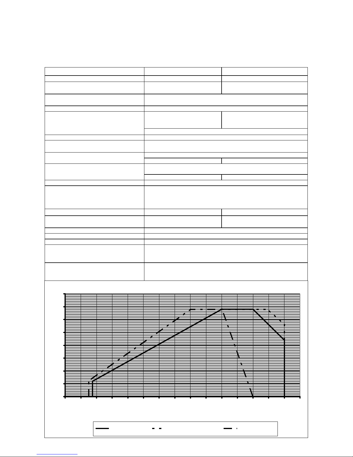
E10.12000.37 L-EUF E10.14000.45 L-EUF
Combustion Power Output Fuel Oil EL: 1500 - 12.000 kW Fuel Oil EL: 1750 - 14.000 kW
Boiler Furnace Pressure According line of operation field and 10 mbars less.
Deviating values on request.
Operation Fields E10 L-EUF according EN 267
0
5
10
15
20
25
30
35
40
0123456789101112131415
Combustion Power Output [MW]
Boiler Furnace Pressure [mbar]
E10.14000.45 L-EUF E10.14000.45 L-EUF with FQ E10.12000.37 L-EUF
5
Overview
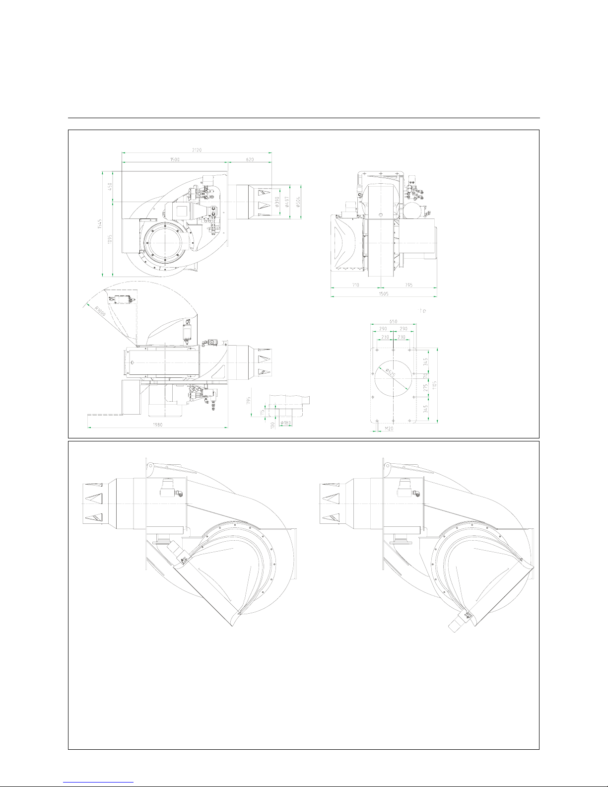
Dimensioned Drawings
EK 10... L-EUF
EK 10...L-EUF
The cover of motor is
removable in case of ope-
ning boiler door for revi-
sion
Drilling Template
Motor with disassembled protection grid
The air intake box can be rotated in
steps of 22,5 °C, the swivelling function,
however, is then not functional.
Note: In pecial cases, the air
intake box can be mounted in a
way that the opening shows to
another direction. The dimen-
sioned drawing will the differ
slightly.
6
Operation
Start-up Mode
Oil Operating Mode
General Safety Functions
Start-up mode
As soon as the furnace system is requi-
red to supply heat the burner control cir-
cuit will close and the program be
started. After the program has run down
the burner will start.
The air damper is closed when the
burner is out of operation.
The automatic furnace controller con-
trols and monitors the starting function.
The electric actuator opens the closed
air damper to its full-load position so
that the burner will sweep the furnace
compartment and exhaust ports at the
required air flow rates. Shortly after the
pre-ventilation process has been star-
ted the lack-of-air cut-out must change
over to operating position within a cer-
tain time, i.e. the minimum air pressure
setting must be reached and maintained
until the burner is turned off. At the end
of the specified pre-ventilation time the
air damper will be moved into its partial-
load position. This operation will be fol-
lowed by the pre-ignition procedure and
the oil feed start.
The solenoid valves will open and thus
allow the pressurized oil to flow to the
nozzle and to the return line. The oil will
be atomized, mixed with the combustion
air and ignited.
A safety period is provided to allow the
flame to develop a proper and steady
pattern. On the termination of the safety
period, a flame signal must have been
received by the automatic furnace con-
troller via the flame monitor and remain
on until the regular shut-off. The start-
up program of the burner has now been
completed.
Oil operating mode
After flame formation, the burner will
shortly remain in the separately set igni-
tion load, and is then run to minimum
output. Then the oil feed will start for
load regulation. The load regulator will
now control the burner automatically
between its partial-load and full-load
stages.
Depending on the heat rate required the
servomotor will via the controller be
given an "open" or "close" signal and
thus increase or decrease the oil and air
flow rates.
This compound control concept will vary
the position of the oil control valve and
air damper and thus adjust the oil flow
rate in relation to the air flow rate.
The stepless control will allow the bur-
ner to be operated at any desired stage
between its partial-load and full-load
positions. The air damper will be closed
when the burner is out of operation and
will thus prevent cold air flowing through
the burner chamber, heat exchanger
and chimney. The interior cooling los-
ses will be greatly minimized.
General safety functions
In case a flame does not develop when
starting the burner (fuel release) the bur-
ner will shut off at the end of the safety
period (shut-off on trouble). A shut-off on
trouble will also occur in the case of flame
failure during operation, air flow failure
during the pre-ventilation phase and pres-
sure failure during the whole period of bur-
ner operation. Any failure of the flame
signal at the end of the safety period and a
flame signal during the pre-ventilation
phase (external light control) will result in
a shut-off on trouble with the automatic
furnace controller being lokked. Die Stö-
rung wird am Display der elektronischen
Regelung und/oder wenn vorhanden
einer Störmeldelampe angezeigt.The
trouble is indicated by the trouble signal
lamp lighting up. The automatic furnace
controller can be unlocked immediately
after a shut-off on trouble by pressing the
unlocking key. The program unit will return
to its starting position and proceed with
the restart of the burner.
A voltage failure will result in a regular
shut-off of the burner. Upon voltage reco-
very there may be an automatic restart
unless another interlock is provided, e.g.
by the safety system. In any case of
trouble the fuel oil supply will be shut off
right away. The program unit will stop at
the same time causing also the trouble
location indicator to stop. The symbols will
indicate the kind of trouble.
When using the burner control system
type BCS all operational and fault messa-
ges may be indicated in plain text on an
optionally available operating and display
module.
When using the Etamatik/VMS/FMS
system, the display is located directly on
the control system, which is incorporated
in the boiler switch cabinet. In the Etama-
tik OEM, the control system is located in
the electric module of the burner, and the
customer interface is also located on this
module or incorporated in the boiler switch
cabinet. In the Etamatik OEM, a pro-
gramming unit could be installed as an
alternative to the customer interface.
sregulierung
g
t
ile
EIN
e
AUS
s
tellung
Leistungsregulierung
EIN
Gasventile
Zündung
Startlast
Teillast
Freigabe
AUS
Betriebsstellung
Vollast
Zündung/Ventile
Pumpe
Teillast
EIN
Freigabe
Leistungsregulierung
Betriebsstellung
Vollast
AUS
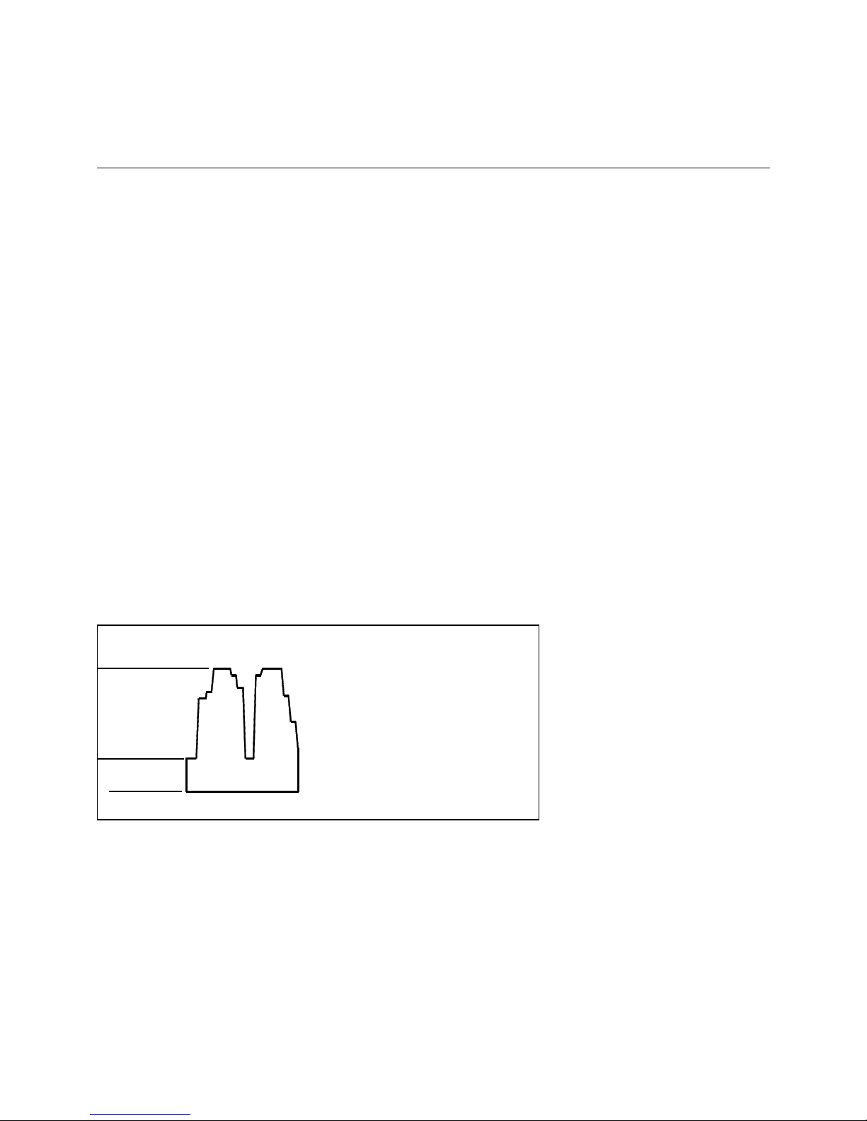
Oil control steepless Gas control steepless
ON OFF ON OFF
Full load
Operating position
Load regulator
Release
Start load
Partial load
Ignition / gas valves
Full load
Operating position
Load regulator
Release
Partial load
Ignition/valves
Pump
7
Operation
Fuel-air Compound Control
Fuel-air compound control
This compound pneumatic control
system with precision-adjustment capa-
bility has been designed to allow the
fuel and air flow rates to be steadily
varied in sliding mode for an adjustment
of the fuel-air ratio over the whole con-
trol range.
In the stepless control mode the load
will be controlled at any point within the
control range depending on the heat
demand.
Electronic compound control:
The air box includes an actuator for
operating the air damper. The oil control
valve incorporates an actuator for adju-
sting the return oil flow rate and thus the
output of the burner.
The actuators for the air and fuel flow
control will be operated depending on
output by the electronic compound con-
trol which will move them into the pro-
grammed positions.
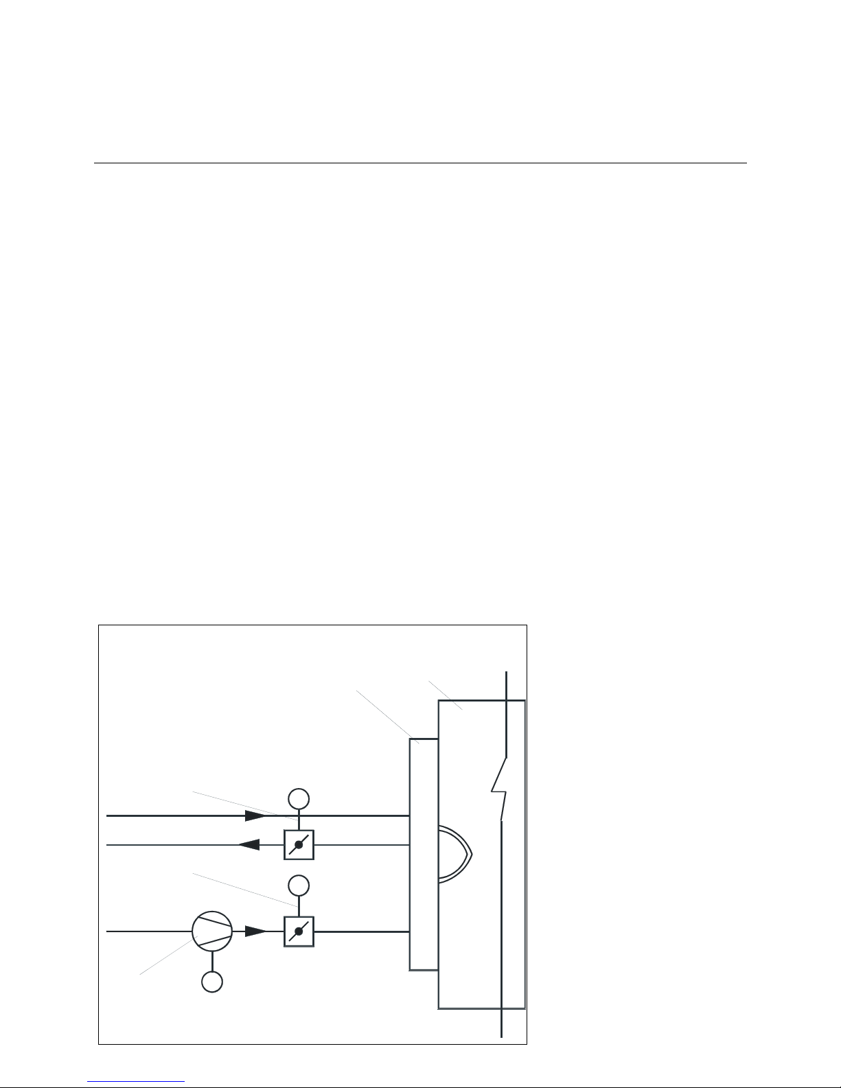
4
Luft
M
M
Öl
Öl
RL
VL
1a
1b
M
3
2
Oil feed
Oil return
Air
Electronic compound control
1a Oil control valve with actuator
1b Air dampers with actuators
2Burner
3Boiler
4 Combustion air fan
8
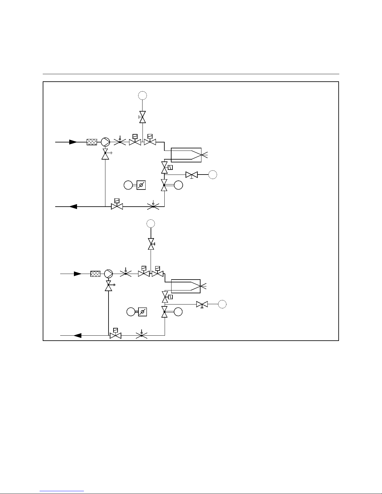
Hydraulic diagramm
120 Air damper
143 pressure gauge option
175 Filter
176 Pump
178 Feed solenoid valve
180 Nozzle rod
181 Return solenoid valve
184 Output control valve
187a Pressure regulating valve
(integrated in pump)
311 Return oil pressure switch
312 Feed oil pressure switch
349 Actuator
In case of TRD 604/72 hr control
items (pos. 311, 312) need to be
tested according to „special construc-
tion design“ or must be installed twice.
312
RL
181
175
187 a
VL
176
311
178
178
M M
120
184
349
349
180
181
PI
143
PI
143
Hydraulic diagram -DIN / EN
RL
175
187 a
VL 176
311
312 178
178
181
180
181
M184
120
M349349
PI
143
PI
143
Hydraulic diagram -TRD 604/72 h

9
Operation
Hydraulic Valves and Instruments Group
The hydraulic valves and instruments
group is an integrated concept that
combines several functions of the
hydraulic systems of burners. Its modu-
lar construction makes it possible to
meet a wide range of requirements and
conditions of installation.
Depending on the level of equipment of
the hydraulic system, oil pressure swit-
ches and pressure gauges (3) may be
installed in the supply and return pipes
of the basic module (1). The solenoid
valve in the supply pipe is of servo-assi-
sted type while the return valve is
directly controlled. The solenoids of the
two valves are electrically connected in
series which will prevent one of the val-
ves being opened alone if any of the
solenoids is defective. For the replace-
ment of the solenoid valves during
maintenance work it should be ensured
that the right valve type is installed in
the correct direction of mounting. For
mounting the solenoid valve in the sup-
ply pipe (type 321F2523) it must be
ensured that the direction of flow shown
be a stamped arrow on the valve flange
is the same as the direction of flow of
the oil (from the pump to the nozzle
rod). The solenoid valve in the return
pipe (type 121 F2523) is marked with a
stamped arrow opposite to the direction
of the oil flow from the nozzle rod back
to the pump.The volume flow control
valve installed in the return pipe con-
sists of a bush pressed into the hydrau-
lic valves and instruments group and
locked against torsion and a control
shaft. As the control shaft is turned, the
contoured configuration of the bush and
shaft will change the open cross section
for the oil flowing back and thus vary the
oil return flow rate. Control shafts with
different control contour parameters are
available for adjustment to various oil
nozzle sizes. This concept ensures that
an excellent control characteristic and a
wide control range can be covered for a
great variety of applications. The control
contour parameter is affixed to the con-
trol shaft by means of an electric mar-
ker. The current position of the control
shaft is indicated by the position dis-
play. From the "min." mark (low load of
burner) the control shaft will turn clock-
wise to the "max." mark (full load of bur-
ner). If the control shaft has been
removed during maintenance work care
should be taken when reinstalling it to
ensure the right mounting position of
the control contour by observing the
centre punch mark on the shaft end
face. In the low load position (min.) the
centre punch mark will in any case point
up (12 o'clock position - see figure).
If the hydraulic valves and instruments
group is used in conjunction with nozzle
rods not approved as safety shut-off
valve according to EN 264, an exten-
sion module (2) is available which
incorporates an additional solenoid
valve each in the supply and return
pipes. The extension module is atta-
ched directly to the basic module. The
modules are sealed against each other
by O-rings.
Metal hoses are used for connection
between the hydraulic valves and
instruments group and the nozzle rod.
The hose lines must be protected
against exterior mechanical damage.
The hoses must be positioned and
mounted in accordance with the appli-
cable technical standards. For the
installation care must be taken not to
introduce torsional or buckling stresses
neither by the mounting procedure nor
by movements at a later stage. Speci-
fied bending radii of the hoses must not
be changed.
Basic module
Extension module
Control shaft installation
Complete hydraulic valves and
Instruments group
3
1
2

10
E 10.1200 L-EUF
Start-up
Burner Head Settings
E 10... L-EUF

11
Installation
Mounting to Boiler
Electrical Connection
Presetting
Adjustment electrical ignition
oil firing operation
Burner plate with gasket strip
Check before burner installation
Check the mixing unit for correct set-
ting; see dimensioned drawing.
Burner head settings
The settings mentioned are factory set-
tings.
They are understood to be recommen-
ded values and may be readjusted
according to burner system conditions,
exhaust gas analysis and combustion
characteristics.
- Set the ignition electrodes according
to the sketch.
- Check the burner pipe mounting
according to Section “Boiler lining for
burners” and the boiler manufacturer’s
specifications.
Electric connection:
The electric connection including all
installation materials as well as joints
and earth terminals must be made in
accordance with the applicable regulati-
ons. For the electrical installation of the
burner reference should be made to the
circuit diagram of the furnace system.
The electric connection of the burner
and gas valves and instruments is allo-
wed to be entrusted to authorized spe-
cialists only.
Burner installation
For mounting the burner to the boiler
make sure the connection plate is pre-
pared in accordance with the dimensi-
ons given in the technical datasheets.
• Install the stud bolts in the connection
plate.
• Put the insulating base and burner in
place and fasten with bolts.
Arrangement of sealing tape on the
boiler
- Evenly stick on self-adhesive tape
according to Figure.
- Adapt the flat gasket by cutting to the
boreholes in the area of the four.
vertically arranged boiler fastening
holes.
- In case of butt joints make sure the
bordering is fitting closely
NOTE: For the installation of the con-
necting cables care must be taken to
provide cable loops of sufficient length
so that the boiler door and burner can
be swung out as required.
After the completion of the electric con-
nection work make a check of the wiring
of the burner electric system. This inclu-
des a check for the direction of rotation
of the burner motor (fan).
Boiler inspection glass cooling
For cooling and cleaning the boiler
inspection glass, a cooling line (e.g. a
hose) may be installed from the burner
to the inspection glass. A connection
piece is provided on the burner for this
purpose.
12
Installation
Boiler Lining
Burner GL/L-EUF
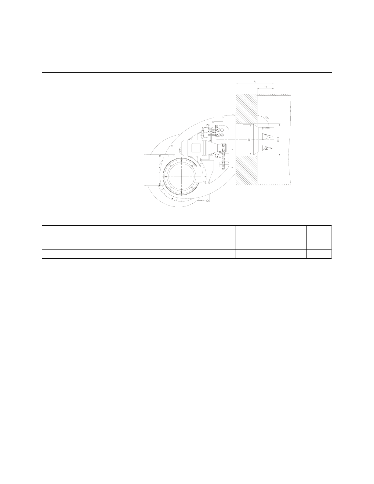
Boiler lining
The burner lining must be installed at
right angles to the burner tube.
Possible trimming work (bevelling, roun-
ding) as is required for reversing boi-
lers, for example, should done at a
diameter not below 70 % of the combu-
stion chamber diameter.
The space between the flame pipe of
the burner and the boiler lining should
be lined with heat resistant material,
such as Cerafelt.
This space is not allowed to be lined
with brickwork.
DF= Combustion chamber diameter
Burnertyp Dimension A Dimension T1 φ D φ D1
Standard 100 verl. 200 verl.
E 10 620 720 820 200 - 250 497 525

13
Installation
Oil Connection
Oil Pressure Control (Feed)
Oil connection
Hoses are used for connection to the oil
lines and stop valves. The hoses must
be installed according to the applicable
standards (relieved of tensile load, free
of distortion) to avoid kinking and
exclude the danger of breakage. Take
care when mounting the oil lines to
bring their ends as close to the burners
as possible and to arrange them in a
way that the boiler door and the burner
can be swung out without any obstruc-
tion.
Refer to the technical documentation for
the line dimensions for the feed and
return lines from the stop valves to the
tank.
Oil filter
A filter must be installed upstream of the
pump to protect the oil pressure pump
and the hydraulic system.
Installation options
• Two-line installation
(separate feed and return lines without
delivery pump)
• Ring line system
(with delivery pump and gas-air sepa-
rator)
Oil hose aplication area
Burner type DN length
[mm]
double sided
connection
bending radius
min. R [mm]
E 10 25 1500 R 1" 250
Instrument mounting
Prior to adjusting the burner make sure
to mount the test pressure gauges for
measuring the feed pressure (Item 2)
and return pressure (Item 1).
A vacuum gauge and pressure gauge
are mounted to the oil pump for measu-
ring the oil pressure.
NOTE: After the burner has been taken
into operation the gauges must be
removed again and the connections
sealed with suitable means. If the gau-
ges are mounted to remain on the bur-
ner they should be fitted with stop
valves.
Oil pressure control (feed)
The feed pressure is controlled by
means of the pressure regulator instal-
led in the pump and should be set at
approx. 25 to 30 bar depending on bur-
ner output and nozzle make. The pres-
sure regulator is operated by turning its
screw. Make sure to fill the pump with
oil prior to taking into operation.
Pump bleeding
Open the feed and return stop valves
and ensure the ring line (if any) is in
operation. Reduce the oil pressure at
the pressure regulating valve. Turn on
the pump by pressing the contactor.
Check the pump for proper direction of
rotation. Check for proper oil delivery
and absence of leaks in the hydraulic oil
system. For bleeding the pump open
the pressure gauge connection, for
example. When taking the burner into
operation proceed by gradually increa-
sing the pressure to operating level (25-
30 bar).
Checking the pressure (oil suction
pressure)
The maximum permissible vacuum is
0.2 bar. At higher vacuum levels the fuel
oil will tend to gas evolution which may
lead to operating trouble. In the ring line
mode of operation the pump oil pres-
sure is not allowed to exceed 5 bar.
1
2
14
General
The burner feed pipe 32-EH is particu-
larly suited for mounting to oil burners
and is designed for the operation of
return plate nozzles with needle shut-
off. The powerful spring of the driving
piston moves the shut-off needle into
closing position, thus always ensuring a
safe shut-off.
The driving piston is operated with oil
tapped from the supplied pipe, and its
opening function is controlled by the
solenoid valve of the hydraulic block.
The piston has a fixed travel.
The final position of the driving piston
can be checked hydraulically and incor-
porated into the control system of the
burner.
During the pre-ventilation of the burner,
the shut-off needle keeps the bore in
the nozzle plate closed and the oil circu-
lates in the feed pipe. When using
heavy fuel oil, the complete hydraulic
system is heated in the pre-scavenging
stage. When the solenoid is turned on,
or after a longer downtime, an imme-
diate atomizing and a perfect ignition
are ensured.
The burner feed pipe is suitable for sup-
ply pressures from 20 to 40bar and oil
temperatures up to 140°C. The ambient
temperature in the vicinity of the coil
should not exceed a temperature of
60°C.
SW 41
SW 41
SW 41
swirl chamber plate
e
adapter
mounting
rod
Needle open Neddle closed Nozzle plate
swivel nut
needle guidance
shut off needle
Nozzle rod linkage 32 - EH
Mounting the nozzle plates
The nozzle plate and the swirl chamber
plate should be installed according to
the attached sketch.
The sealing surfaces on the adapter, on
both sides of the swirl chamber plate
and on the nozzle plate must not be
damaged because this would endanger
the proper sealing. When sealing these
surfaces, never use material from other
manufacturers.
Remove the swivel nut from the feed
pipe, check that the needle guidance in
the swirl chamber plate is sliding pro-
perly over the needle head and place
the plates into the nut evenly in proper
position and proper sequence.
Now the nut together with the plates is
carefully placed over the needle and
tightened by hand as firm as possible.
The cap nut is firmly tightened with a
spanner. Spanner surfaces are provi-
ded on the adapter to counter with the
feed pipe when screwing down or off
the cap nut. These surfaces are desi-
gned for this purpose only!

15
Nozzle rod linkage 32 - EH
Connections
The connections on the block of the
feed pipe are identified as follows:
S Oil supply to the nozzle and to the
hydraulic system of the needle
actuation. A filter with a mesh size
smaller than 50 µm should be pre-
connected. The pressure should
be kept above 20bar.
MS Here, the supply pressure of the
nozzle is available. A pressure
gauge or a pressure sensor can
be connected to evaluate this
pressure.
R Oil return from the nozzle. A pres-
sure or a quantity governor can be
connected for fuel oil flow control.
MR Here the return pressure of the
nozzle is available. A pressure
gauge or a pressure sensor can
be connected to evaluate this
pressure.
L Oil return from the hydraulic
system of the needle actuation. In
principle, this oil should be allo-
wed to flow off without back pres-
sure. If this pipe is connected to a
ring main having a low overpres-
sure, it is essential to observe that
the pressure at connection „S“
must in any case be at least 20
bar higher than that pressure
which is applied at connection “L”.
Only then, the proper needle
function is ensured.
C Here, the switching pressure of
the needle piston is available. A
pressure gauge or a pressure
sensor can be connected to eva-
luate this pressure. The pressure
is lower than the pressure at con-
nection “S” when the needle is
closed and during the switching
procedure of the needle piston.
Only during the time while the
needle is fully open, there will be a
pressure that is as high as the
pressure at connection “S”. These
properties allow the final position
of the needle to be checked
hydraulically.
When selecting the screwed connec-
tions, make sure that the ducts in the
connecting block of the feed pipe can
not be covered, not even in part. Even a
partial covering of these ducts will result
in a malfunction of the feed pipe.

16
Nozzle rod linkage 32 - EH
Function
During the pre-scavenging stage, both
the external solenoid in the supply line
and the external quantity or pressure
governor in the return line are open.
The attached solenoid is de-energized
and the valve used for needle actuation
is closed, the spring-loaded rod thus
keeps the needle in the bore of the
nozzle plate at the front of the feed pipe
closed so that the oil cannot reach the
furnace chamber too early. The pres-
sure at connection “C” is 0 bar or equal
to the ring main pressure if the connec-
tion “L” has been connected to a ring
main. The oil circulates from connection
“S” via the swirl chamber plate in the
nozzle through the feed pipe to the con-
nection “R”, thus warming it up to opera-
ting temperature. (For heavy oil only)
Operating voltage and type of current
are indicated on the attached coil. The
moment the attached solenoid is turned
on, the oil is released for needle actua-
tion; the rod is withdrawn, and the
nozzle needle is opened. During the
short time where the piston moves from
closed to open needle position, the
pressure at connection “C” is always at
least 2bar lower than the pressure at
connection “S”. From the moment on
where the piston reaches its final posi-
tion and the needle is opened fully, a
pressure is applied at connection “C”
which is as high as the pressure at con-
nection “S”.
The interruption of the power supply to
the attached solenoid causes the
needle to be closed by means of the
spring. The oil outflow on the nozzle will
stop immediately.
The pressure at connection “C” will go
down to 0 bar or reaches again the
same level as in the ring main if connec-
tion “L” is connected with the ring main.
The circulation from connection “S” via
the swirl chamber plate to connection
“R” will still take place. The temperature
of the feed pipe is thus maintained.
Service
Normally, the burner feed pipe is
maintenance-free.
The only moving part in the feed pipe is
the rod linkage used for actuating the
needle with the piston. After a longer
period, the O-rings could be worn out.
For replacement, complete O-ring sets
are available.

17
Start-up
Return Nozzle Rod RDG 1250
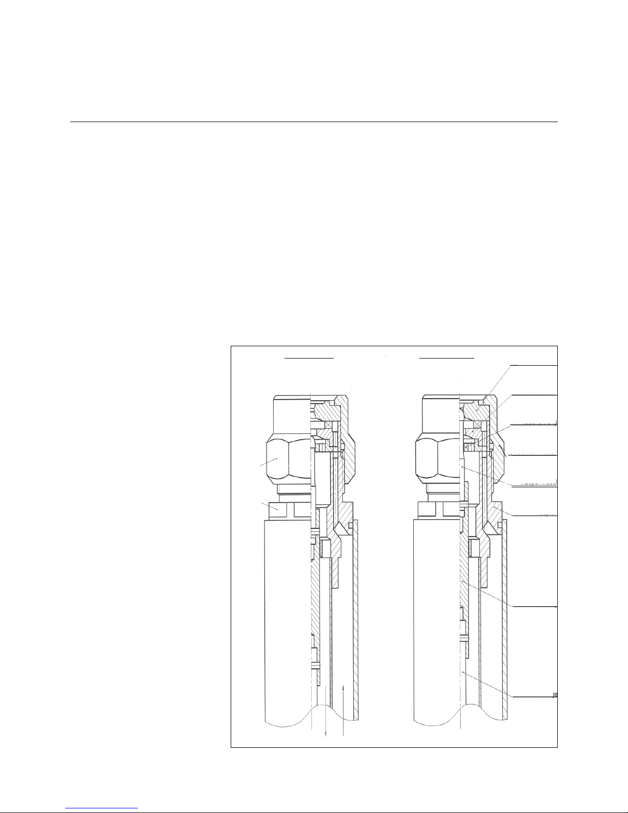
Function description
The return nozzle rod RDG 1250 is for
return nozzle without integrated needle
valve and comes with M14 screw con-
nection (for example Sonic DZ 1000,
CBM M14).The locking mechanism
consisted of a slider with seal ring (Pos.
2 and 6) in the forward flow section and
a needle valve (Pos. 5) in the return
flow section, using the sliding rod con-
trol by a hydraulic control-piston system
located at the back of the nozzle rod.
The opening pressure of RDG 1250 is
about 3 bar in forward flow section or 13
to 20 bar in return flow section. When
the solenoid valves are open, the pres-
sure from the oil would retract the con-
trol-piston via the pressure channel
(Pos. 7) and then push open the slider .
Both the control-piston and sliding rod
with needle valve would remain open as
long as there is an existing oil pressure.
The same oil pressure would keep the
slider open. Under normal circum-
stances, both locking mechanisms
would open at the same time. The oil in
the forward flow section would exit
through the nozzle head to be mixed
with the air for combustion. The remai-
ning oil would be redirected through the
return holes of the nozzle back into the
return flow section of the nozzle rod
assembly. When it is not in operation,
the swirl plate in the nozzle head blocks
the return flow.The return oil flow rate
can be adjusted accordingly using a
pressure control valve If the pump pres-
sure is too low (<20 bar), thereby pre-
venting the control needle from opening
all the way, variations in throughput are
to be expected as the needle position
will affect the return oil flow.
Control-piston opening distance H is set
in the factory at 9mm. Any adjustment
at installation site is not necessary.
1
5
3
6
4
7
2
H
The Control piston
opens at ca. 13 bar;
Fully open at 20 bar.
Close at 10 bar.
1 Return Nozzle
2 Slider
3 Spring (Forward)
4 Sliding rod
5 Needle valve
6 Seal ring (Forward)
7 Pressure channel
Distance H = 9 mm
Forward
Valve
18
Start up
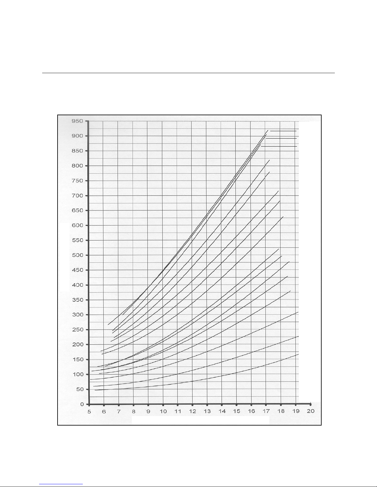
Nozzle selection „Sonic“
160 kg/h
240 kg/h
300 kg/h
350 kg/h
400 kg/h
450 kg/h
500 kg/h
550 kg/h
650 kg/h
700 kg/h
750 kg/h
800 kg/h
850 kg/h
900 kg/h
950 kg/h
1000 kg/h
Diagram - of Sonic-Spray return nozzle DZ 1000-60°
with controlled return
Light fuel Oil
Feed pressure 28bar
Return nozzles of the type Sonic-
Spray are available in different ratings
with an angle of spray of 45°, 60° or
80°.
The 45° nozzles are preferably used
for reversed-flow furnaces while the
60° and 80° nozzles are operated in
three-pass boilers and swirl-type
mixing installations, respectively.
Quantity Oil Nozzle [kg/h]
Return Pressure at the Hydraulicblock [bar]

19
Start-up
Checking Procedure
Check the following prior to the
initial operation of the boiler system:
• Take care to observe the operating
instructions supplied by the boiler
manufacturer. The boiler must be
mounted ready for operation.
• Ensure that the heating system is filled
with water to capacity.
• Check the complete system for correct
electrical wiring.
• Check the burner motor for correct
direction of rotation.
• Check for the proper setting of the
temperature and pressure controllers,
limiters, safety switches and electrical
limit switches.
• Bleed the fuel-carrying lines (make
sure they are free of air).
• Check tank, lines and oil pump are fil-
led with oil and correct oil nozzle is fit-
ted.
• Check the oil hydraulic system is free
of leaks.
• Check the exhaust gas ports are ope-
ned and adequate fresh air intake is
ensured.
• With burner in starting position check
that air damper is in „CLOSED“ posi-
tion.
• Check that automatic furnace control-
ler is unlocked and in its original posi-
tion.
Oil start-up
Open all shut-off valves of oil supply
system.
• Set fuel selector switch to its „Oil“ posi-
tion.
• Fill pump with oil.
• Mount pressure gauge in the feed line
and return line.
• Mount the pressure gauge for
checking the pump suction pressure.
Bleeding
Shortly start the burner and check for
proper direction of rotation. Bleed the oil
line and oil pump.
CAUTION: The hydraulic system has
been filled with test oil by the manufac-
turer. This may cause ignition trouble
when initially operating the system. To
protect the pump, the oil pressure con-
troller is factory-set at zero pressure.
When starting the burner take care to
increase the oil pressure slowly to the
operating level.
Prior to the initial fuel feed start
make a functional test of the burner
program flow:
Oil system:
• Open all shut-off valves of the oil sup-
ply system.
• The oil solenoid valve in the feed line
disconnect on the terminal strip (see
Circuit Diagram).
• Start burner and check program flow
for correct start-up sequence.
1. Fan starts.
2. Pre-ventilating damper.
3. Air pressure check.
4. Partial-load air damper.
5. Ignition.
6. Valves open (disconnected valve
remains closed).
7. Shut-off upon trouble after expiry
of safety period (see automatic
furnace controller).
• Reconnect the valve.
• Unlock the automatic furnace control-
ler.

20
Adjusting Instructions
Air Flow Rate Adjusting Procedure
Adjusting procedure
• Set the selector switch to its "Manual"
or "Hand" position.
Air flow rate adjustment
The air control curve of the compound
controller is factory-set so that the air
damper is closed in minimum position
and open in maximum position.
The combustion air flow rate required
for proper fuel combustion is controlled
by an electronic fuel-air compound con-
trol system over the full load range. A
check is made by analyzing the exhaust
gases.
For the gradual adjustment of the
load points (fuel flow rate, air flow
rate), a procedure should be used as
described in the operating instruc-
tions for the electronic compound
control system.
A fuel test should be made at each point
if possible.
This manual suits for next models
1
Table of contents
Popular Burner manuals by other brands


Dyna-Glo
Dyna-Glo DGH474CRN manual

Sime
Sime MACK 6 Installation, use and maintenance instructions

Unigas
Unigas N18 MANUAL FOR INSTALLATION, OPERATION AND MAINTENANCE

John Lewis
John Lewis 85330112 Pre-assembly preparation

Riello
Riello 826 T2 Installation, use and maintenance instructions

Meec tools
Meec tools 008484 operating instructions

YOKOI KIKAI KOSAKUSHO
YOKOI KIKAI KOSAKUSHO HOPE CJ-1 Handling manual

EcoSmart Fire
EcoSmart Fire Vision manual

baltur
baltur BT 40G instructions

CIB UNIGAS
CIB UNIGAS LMV5 Series Manual of installation - use - maintenance

Ekoterm
Ekoterm GP sc Series Installation, operation and maintenance manual

baltur
baltur BGN 60 LX Startup guide