Echelon 100150-201 User manual

LumInsight IoT Gateway and Base Station – Ethernet Rev. B (July 2018)
Setup Guide (Network Configuration) 1 078-1074-01B
LumInsight IoT Gateway and
Base Station – Ethernet
Setup Guide (Network Configuration)
Models 100150-201 and 100150-281
Introduction
LumInsight IoT Gateway and Base Station are a set of
Echelon’s Edge Servers for use with the LumInsight 2
Central Management System (CMS). The Gateway or
Base Station manages a network of lighting controllers
and other devices over a LumInsight RF network. The
data from the Gateway or Base Station is back-hauled
over a LAN/WAN or Cellular connection. This guide is
used to set up the LAN/WAN connection.
Setup Guide Overview
This document provides the instructions needed for
network configuration for access by a LumInsight CMS.
The network settings configuration is end-user specific
and requires the appropriate IP address, Netmask, and
Default IP Gateway to be obtained from the IT staff at the
location where the Ethernet Gateway will be installed. A
LumInsight IoT Gateway Network Information Request
(NIR) Form must be completed by the customer’s IT staff.
Information about the NIR form is provided at the end of
this guide.
Parts and Accessories
The following parts and accessories are required for the
LumInsight IoT Gateway and Base Station network
configuration:
• Desktop or laptop (recommended) computer with
an Ethernet port
• CAT 5 patch cable
• LumInsight IoT Gateway (Ethernet model number
100150-201) or Base Station (Ethernet model
number 100150-281)
Network Settings Configuration
CAUTION: Make sure that the computer being used is
not connected to any other network and is configured
to receive an IP address from a DHCP server.
To configure the network settings for a LumInsight IoT
Gateway and Base Station, perform the following steps:
1. Open the IP66 enclosure and locate the CloudGate
device inside (refer to the figure below).
CloudGate Device
2. Connect one end of the Ethernet cable to the CloudGate.
3. Connect the other end of the Ethernet cable to a
computer (refer to the figure below).
Ethernet Cable Connection
4. Connect the power adapter to the CloudGate and apply
power.
As the CloudGate boots, the system state LED turns
orange; wait until it turns green.
When the boot process completes, the computer will
have an active network connection with a valid IP
address.
5. Open a browser window and go to the address
http://192.168.1.1.
A CloudGate Login page should appear as shown in the
screen below, confirming a good Ethernet connection to
the CloudGate.
CloudGate Login Page
6. Enter the following credentials to login to the CloudGate
web interface:
Username: admin
Password: @Echelon123!
7. On the CloudGate Home page, click on the Interfaces
menu item and then select the Main Ethernet option as
shown in the screen that follows.

Rev. B (July 2018) LumInsight IoT Gateway and Base Station – Ethernet
078-1074-01B 2 Setup Guide (Network Configuration)
CloudGate Home Page
At this point, the settings on the CloudGate Main Ethernet
page should appear as shown in the screen that follows.
CloudGate Main Ethernet Page
8. In the General section, verify the following settings:
• Set “Mode” to “WAN”.
• Set “WAN/LAN Switchover” to “No”.
9. In the IP Config section, configure the following settings:
• Set “IP address” to the IP address value from the
completed LumInsight IoT Gateway NIR Form.
• Set “Netmask” to the Netmask value from the
completed LumInsight IoT Gateway NIR Form.
• Set “Gateway” to the default Gateway IP value
from the completed LumInsight IoT Gateway NIR
Form.
• Set “DNS 1” to the corporate DNS setting value
from the completed LumInsight IoT Gateway NIR
Form, or use 8.8.8.8.
10. Click the Save Changes button to save settings.
11. Select the Firewall menu item and verify that “WAN
Local” is set to “Accept”.
12. Click the Save Changes button to save settings.
13. Wait 10 seconds.
14. Power off the Ethernet Gateway or Base Station.
15. Disconnect the Ethernet patch cable from the Ethernet
Gateway or Base Station.
16. Connect the Ethernet Gateway or Base Station to the
Ethernet cable that is connected to the desired LAN.
17. Apply power to the Ethernet Gateway or Base Station.
LumInsight 2 CMS Connection
The step-by-step instructions in this document describe
setting up the network configuration and IP address of the
Gateway or Base Station.
After completing the steps in the document, additional
considerations include:
1. The Gateway or Base Station must be set up to
connect through the Internet to the LumInsight Cloud
CMS. Doing so requires a valid LumInsight Cloud
subscription. Contact Echelon Support for setting up
and connecting to the Cloud CMS.
2. A VPN credential is recommended to be set up by the
Network Administrator and provided to Echelon
Customer Service to enable the Gateway or Base
Station to communicate with the LumInsight Cloud
CMS, and to help setup or troubleshoot Gateways
and Base Stations in the network.
Additional References and Contact
Additional information and related documentation can be
found on the Echelon web site at www.echelon.com.
Please refer to the Echelon Customer Support web site at
http://echelon.com/support for more information.
© 2018 Echelon, Echelon logo, and LumInsight are trademarks of Echelon
Corporation registered in the United States and other countries.

LumInsight IoT Gateway and Base Station – Ethernet Rev. B (July 2018)
Setup Guide (Network Configuration) 3 078-1074-01B
LumInsight IoT Gateway Network Information Request (NIR) Form
It is recommended that the Ethernet Gateway be configured prior to being installed, and that the configuration of the Ethernet
Gateway be performed by the customer’s IT/Network Administrator.
Prerequisites
The network settings (IP address, Subnet Mask, and Default Gateway) must be obtained from the IT/Network Administrator
of the network location where the Ethernet Gateway will be installed.
If the Ethernet Gateway is assigned a Static IP address, the IP address must be outside of any/all DHCP Server’s Scope(s)
that are active on the network.
The local network must also allow outbound connections via ports 8883 and 123 for a secure connection. The
local network should also provide access to pool.ntp.org and nist.time.gov. (The LumInsight Cloud CMS does not require
any inbound ports to be open.)
The following information is to be provided by customer’s IT/Network Administrator:
IP Address: _____._____._____._____
Netmask: _____._____._____._____
Default Gateway: _____._____._____._____
DNS: _____._____._____._____
VPN Login:
VPN Password:
Echelon Customer Support
For assistance, please refer to the Echelon Customer Support web site at http://echelon.com/support.
This manual suits for next models
1
Popular Gateway manuals by other brands
DEUTSCHMANN AUTOMATION
DEUTSCHMANN AUTOMATION UNIGATE CX-EtherNet/IP 2Port CANopen manual
IFM Electronic
IFM Electronic CR3146 operating instructions
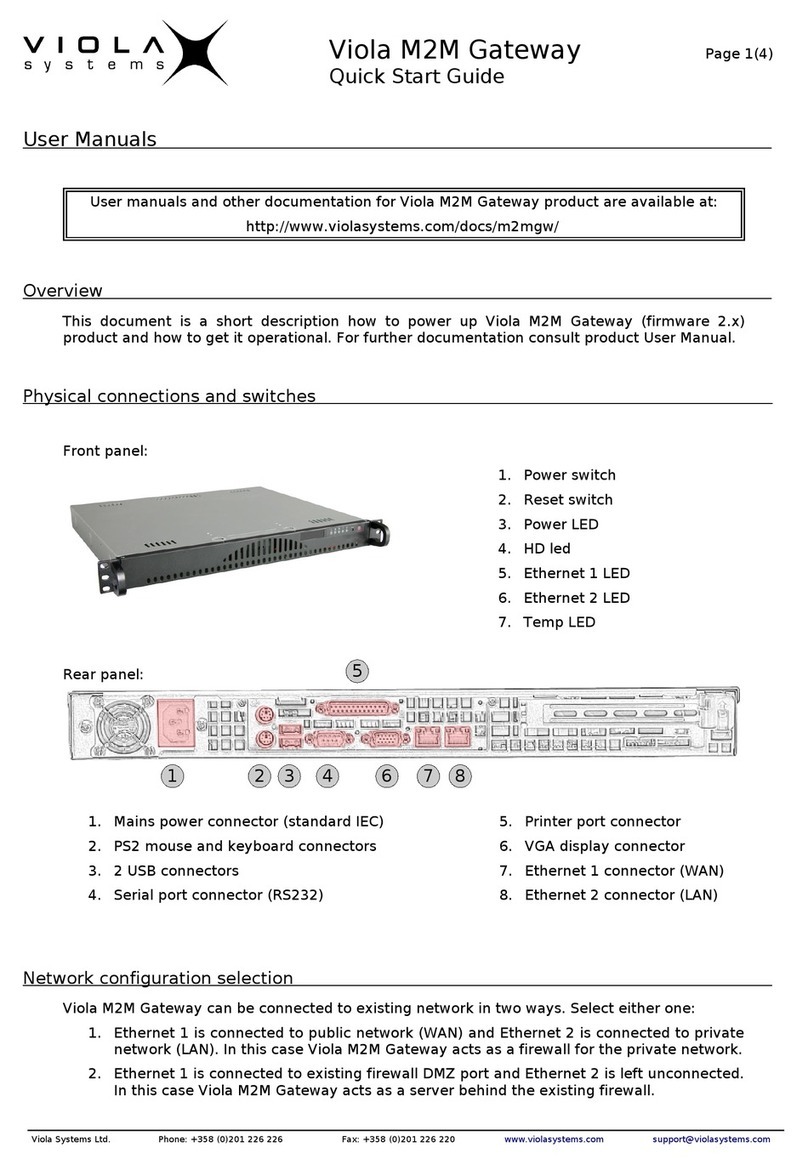
Viola Systems
Viola Systems M2M quick start guide
Digi
Digi ConnectPort X2e Setup instructions
Usr
Usr Courier USR3513 user guide
Cisco
Cisco VG30D quick start guide
