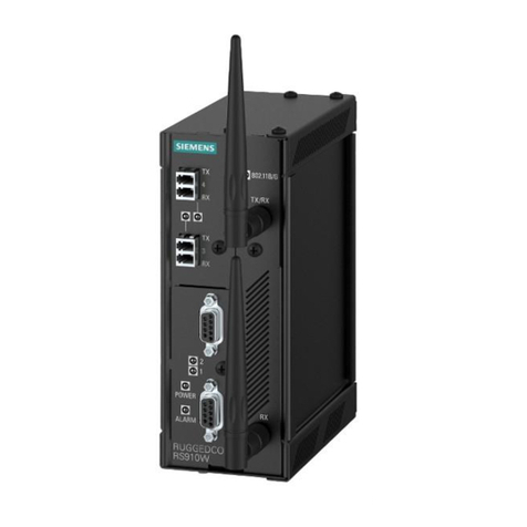
Echelon i.LON 1000 User manual

i.LON™1000 Internet
Server
User’s Guide
Version 1.01
078-0184-01B

Echelon, LON, LONWORKS, LonTalk, LonBuilder, LonManager,
Neuron, 3120, 3150, LONMARK, NodeBuilder, and the Echelon
logo are trademarks of Echelon Corporation registered in the
United States and other countries. LonMaker, LNS, and i.LON
are trademarks of Echelon Corporation.
No part of this publication may be reproduced, stored in a
retrieval system, or transmitted, in any form or by any means,
electronic, mechanical, photocopying, recording, or
otherwise, without the prior written permission of Echelon
Corporation.
Printed in the United States of America.
Copyright ©2000-2001 by Echelon Corporation.
Echelon Corporation
415 Oakmead Parkway
Sunnyvale, CA 94085, USA

i.LON 1000 Internet Server User’s Guide i
Preface
The i.LON 1000 Internet Server is a high performance server
that provides connectivity between LONWORKS®control
networks and Internet Protocol (IP) data networks, while
enabling access to network variable information by standard
web browsers. This user’s guide describes how to install,
configure, use, and manage the i.LON 1000 as a router and web
server.

ii Contents
Purpose
This user’s guide describes how to install the i.LON 1000 hardware, and configure, use, and
manage the i.LON 1000 as a router and web server.
Audience
This user’s guide is intended for Echelon customers, OEMs, and system designers and
integrators with knowledge of control systems and IP networking.
Content
The i.LON 1000 Internet Server User’s Guide includes the following content.
•Chapter 1, Introduction, provides an introduction to the i.LON 1000 Internet Server.
•Chapter 2, Shipping Content and Hardware, describes the contents of the iLON box, the
i.LON 1000 hardware, the various ports, and mounting options.
•Chapter 3, i.LON 1000 Software, describes the various i.LON 1000 software components,
and the PC utilities used to interact with the i.LON 1000 Internet Server. PC software
installation, and i.LON 1000 software upgrade procedures are also covered in this
chapter.
•Chapter 4, The i.LON 1000 Console Application, describes how to use the console
application to set up the i.LON 1000’s IP information such as IP address, subnet mask,
default gateway, etc.
•Chapter 5, LONWORKS/IP Channels Background and Definition, provides the theoretical
basis for using LONWORKS /IP channels. This chapter introduces the concept of
tunneling LONWORKS packets through an IP network.
•Chapter 6, IP Resources Required to Create LONWORKS/IP Channels, outlines the IP
resources necessary to support LONWORKS over IP and provides a simple worksheet of
what TCP/IP resources must be provided by the local network administrator.
•Chapter 7, Creating a LONWORKS/IP Channel, provides a step-by-step guide (in tutorial
form) to setting up a LONWORKS /IP channel and using i.LON 1000 Internet Servers in
layer 3 routing mode. The tutorial covers i.LON 1000 devices as well as LONWORKS/IP
devices created on PCs running LNS 3.01 or better.
•Chapter 8, LONWORKS/IP channel Timing Considerations, discusses timing parameters
and how they should be set up depending on the sort of IP network you are using for your
LONWORKS/IP channel (i.e LAN, Internet, etc.).
•Chapter 9, Creating an i.LON 1000 Web Page, provides a step-by-step guide (in tutorial
form) to monitoring and controlling a LONWORKS network using the i.LON 1000 web
server and a standard web browser.
•Chapter 10, Advanced Usage of the <iLonWeb> HTML Tag, contains advanced
information on creating HTML web pages.

i.LON 1000 Internet Server User’s Guide iii
•Chapter 11, i.LON 1000 Web Page Security, describes how to add basic web
authentication to password protect some or all of the web pages on your i.LON 1000
Internet Server.
•Chapter 12, Advanced Topics, Contains information on advanced topics, including
Aggregation, MD5 Authentication, LonMark Resource Files, DHCP, Event Logs, and
SNMP.
•Appendix A, Console Application, provides an overview of the Console Application and
describes the console commands, the i.LON 1000 boot process, and the line editor.
•Appendix B, Web Page Examples, explains how to install and use the Web server
application example, including a LonMaker network and web pages, that ships with the
i.LON 1000.
•Appendix C, Client Side Programming Examples, contains two examples of using
JavaScript to create i.LON 1000 web applets.
•Appendix D, i.LON 1000 Web Server Errors, contains a list of errors that may be
returned by the i.LON 1000 web server and some troubleshooting information.

iv Contents
Contents
Purpose ii
Audience ii
Content ii
1 Introduction
Introduction 1-2
Shipping Contents 1-2
Optional Accessories 1-2
2 Shipping Content and Hardware
i.LON 1000 Internet Server Hardware 2-2
Ports, LEDs, Switches & Wiring Options 2-3
Input Power 2-3
Twisted Pair LONWORKS Network Connection 2-4
TCP/IP Connection 2-4
Console and Serial EIA-232 Ports 2-4
Control Switches 2-5
Diagnostic LEDs 2-5
Front Panel LED 2-5
Rear Panel LED 2-5
i.LON 1000 Internet Server Mounting Options 2-6
Wall Mount 2-7
EIA 19-inch Rack Mount 2-7
Applying Power and Installation Troubleshooting 2-9
3 i.LON 1000 Software
i.LON 1000 Software and PC Utilities 3-2
i.LON 1000 Applications 3-2
Console Application 3-2
Router Application 3-2
Data Server Application 3-2
Web Server 3-3
i.LON 1000 PC Utilities 3-3
Configuration Server 3-3
Web Tag Wizard 3-3
Web Server Parameters Application 3-3
i.LON 1000 Firmware 3-3
Installing the i.LON 1000 Software on Your PC 3-3
Updating the i.LON 1000 Firmware 3-4
4 i.LON 1000 Console Application
Setting Up the i.LON 1000’s IP Information 4-2
5 LonWorks/IP Channels, Background and Definition
Introduction to the LONWORKS/IP Channel 5-2
6 IP Resources Required to Create LONWORKS/IP Channels
Information/Resources to be Acquired From Network Administrator 6-2

i.LON 1000 Internet Server User’s Guide v
Firewall/Router Configuration Information to be Supplied to the Network Administrator 6-3
7 Creating a LonWorks/IP Channel
Creating a LONWORKS/IP Channel 7-2
Designing a LonMaker Network Containing LONWORKS/IP Channels 7-9
Defining an i.LON 1000 as a LONWORKS Router 7-10
Verifying Router Functionality 7-11
8 LONWORKS/IP Channel Timing Considerations
LONWORKS/IP Channel Timing Considerations 8-2
Channel Timeout 8-2
Packet Reorder Timer 8-3
Channel Delay 8-3
Using SNTP When Creating LONWORKS/IP Channels 8-3
Specifying System SNTP Servers 8-3
Specifying SNTP Servers for a Channel or Device 8-4
Using a Third-Party SNTP Client on the Configuration Server PC 8-5
Choosing an SNTP Server 8-5
9 Creating an i.LON 1000 Web Page
Overview of Creating i.LON 1000 Web Pages 9-2
Required Hardware 9-2
Required Software 9-2
Setting Up The Hardware 9-2
Creating The LonMaker Network 9-3
Creating Web Pages 9-8
How the HTML Code Works 9-11
10 Advanced Usage of the <iLonWeb> HTML Tag
<iLonWeb> Web Tag Format 10-2
FUNC Attribute 10-2
Func=ShowValue 10-2
FUNC=Include 10-2
FUNC=CreateSymbol 10-3
SYMBOL Attribute 10-3
Network Variable Symbols (NVL_ and NVE_ Prefixes) 10-4
System Symbols (ILON_ Prefix) 10-11
Web Tag Attributes 10-12
FIELD: 10-12
FORMAT: 10-13
LonMark Standard Network Variable Type (SNVT) Device Resource Files 10-13
User Network Variable Type (UNVT) Device Resource Files 10-13
Built-in Formats 10-13
PROPAGATE: 10-14
WAIT: 10-14
Working with Forms 10-15
Opening a Form 10-15
Netscape Browser Constraint 10-16
Submit or Reset a Form 10-16
Refresh a Form 10-17
Form Element Functions 10-17
CheckBox 10-18
Hidden 10-18

vi Contents
RadioButton 10-19
TextArea 10-19
TextField 10-20
11 i.LON 1000 Web Page Security
Overview of i.LON 1000 Web Page Security 11-2
Setting Access Restrictions 11-2
Users and Groups 11-3
Locations 11-5
Realms 11-5
Sample WebParams.dat file 11-6
12 Advanced Topics
Aggregation 12-2
MD5 Authentication 12-2
Device Resource Files 12-4
Using DHCP with the i.LON 1000 Internet Server 12-4
DHCP Server Failure 12-5
i.LON 1000 System Event Log 12-5
Event Types 12-5
Using i.LON 1000 Devices with SNMP 12-7
Appendix A - Console Application
Console Application A-2
Interrupting the Boot Process A-2
The Bootrom State A-2
Console Command List A-2
Special Control Commands A-4
Command History and Line Editing A-5
Line Editor Commands A-5
Movement and search commands A-5
Insert commands A-6
Editing commands A-6
Special commands A-7
Appendix B - Web Page Examples
i.LON 1000 Web Server Application Examples B-2
Web Page Examples B-3
Monitor Local Network Variable (exampg1.htm and exampg6.htm) B-3
Monitor a Remote Network Variable (exampg2.htm) B-3
Change a Local Output Network Variable (exampg3.htm) B-3
Change a Remote Input Network Variable (exampg4.htm) B-4
Evaluate and Calculate with JavaScript (exampg5.htm) B-4
Display the Local i.LON 1000 Symbol Values (index.htm) B-4
Appendix C - Client Side Programming Examples
Loading a Network Variable Value into a JavaScript Variable C-2
Automatically Refreshing Web Pages Using JavaScript C-3
Appendix D - i.LON 1000 Web Server Errors
HTTP Errors D-1

i.LON 1000 Internet Server User’s Guide 1-1
1
Introduction
This chapter provides an introduction to the i.LON 1000
Internet Server, including its applications, hardware, software,
and utilities.

1-2 Introduction
Introduction
The i.LON 1000 Internet Server provides reliable, secure Internet access to LONWORKS
devices.
LONWORKS control networks are the worldwide standard for networking controls and
machines in building, industrial, home, transportation, and utility automation applications.
Internet Protocol (IP) based data networking is the worldwide standard for moving data over
the Internet, Local Area Networks (LANs), and Wide Area Networks (WANs). Echelon's
i.LON 1000 Internet Server seamlessly links together these control and data networking
standards. By allowing the millions of Internet-ready LONWORKS devices already in use to be
monitored, controlled, accessed, manipulated, and updated over the Internet, the i.LON 1000
opens a new world of applications, markets, and business opportunities.
Figure 1-1 i.LON 1000 Front Panel
The i.LON 1000 offers unparalleled performance and reliability. Certified under the Cisco
NetWorks™ program, the i.LON 1000 integrates Echelon's control networking and routing
expertise together with Cisco's Network Foundation Technologies. The result is a Layer 3
LONWORKS router that offers very high packet throughput for demanding process control,
building automation, utility, transportation, and telecommunications applications. Cisco
certification is your assurance that the i.LON 1000 has been both rigorously tested and will
meet the needs and standards of Information Technology (IT) managers worldwide.
Adherence to the EIA proposed standard for tunneling ANSI/EIA 709.1 packets over IP
ensures that communications through the i.LON 1000 are both open and interoperable.
Power
LED

i.LON 1000 Internet Server User’s Guide 1-3
Internet
131.1.10.6
143.77.105.27
243.47.185.9
IP Routers
Company WAN
53.107.155.9
248.17.15.44
Figure 1-2 i.LON 1000 Application
The i.LON 1000’s built-in Web server allows control information (such as network variables
representing temperature, occupancy, speed, etc.) to be accessed easily through a web
browser. This password-controlled feature provides access to LONWORKS monitoring and
control data from anywhere without the need for special software tools, over LANs, WANs, or
the Internet.
The i.LON 1000 is unique in its ability to support both peer-to-peer and master-slave
network communications. This powerful feature allows remotely located devices to
communicate over IP networks in the same way they would if they were co-located. Devices
on different floors of a building, scattered across different manufacturing pods, or located in
retail branches across the world can be seamlessly and transparently linked together, and
connected to far-flung corporate data and ERP networks.
The impressive performance of the i.LON 1000 is due to the combination of a powerful 32-bit
RISC processor and Echelon's LONWORKS/IP software architecture. The result is very high
packet throughput in control networks with large numbers of nodes and very fast monitoring
and display requirements.
The i.LON 1000 can be installed using standard LONWORKS installation tools. For example,
the i.LON 1000 is fully supported by tools using Echelon's LNS™ network services
architecture (such as the LonMaker™ Integration Tool), which provides quick setup,
configuration, and application-level interoperability. From the perspective of the IT network,
the i.LON 1000 is viewed as a typical IP host. Like other IP hosts, the i.LON 1000 supports
standard Internetworking protocols: TCP/IP, UDP, DHCP, SNMP (MIB II), ICMP, SNTP,
TOS, MD5, HTTP, and FTP. In addition, packet aggregation parameters, addressing, IP
bandwidth utilization, and security can all be adjusted via the IP network.

1-4 Introduction

i.LON 1000 Internet Server User’s Guide 2-1
2
Shipping Content &
Hardware
This chapter describes the i.LON 1000 Internet Server
hardware and explains the various mounting and cabling
options.

2-2 Shipping Content and Hardware
Shipping Contents
Table 2-1 describes the items shipped with the i.LON 1000 Internet Server.
Table 2-1 i.LON 1000 Shipping Contents
Item Description
i.LON 1000 CD The CD contains i.LON 1000 PC software utilities and a copy of the
i.LON 1000 firmware.
i.LON 1000 Internet
Server User’s Guide The User’s Guide describes how to install the i.LON 1000, and
configure, use, and manage the i.LON 1000 as a router and Web server.
i.LON 1000 Internet
Server Mounting
Template
A template to accurately measure the placement of the i.LON 1000 unit
before mounting it onto a wall or panel.
10BaseT Ethernet Cable This cable connects the 10BaseT cable provided between the 10BaseT
port on the i.LON 1000 and an IP network port.
Null-Modem Cable This cable connects the null-modem cable provided between the Console
port on the i.LON 1000 and a terminal (or an available COM port on a
PC running a terminal emulation program).
BLAT Mating Connector
Plug A two-position orange network connector for attachment to a
LONWORKS twisted-pair channel. Weidmüller PN 148426.
BL Mating Connector
Plug A two-position black connector for power input. Weidmüller PN 125911.
Optional Accessories
i.LON 1000 accessories include a universal (100-240 VAC input) regulated 24VDC external
power supply and 19-inch rack-mounting brackets, which can be purchased separately.
Table 2-2 Optional Accessories
Accessory Model Number Description
24VDC External
Power Supply
72901-p (where
p designates the
style of power
cord)
i.LON 1000 EXTERNAL POWER SUPPLY UNIT.
Power Barrel Connector Specifications: ID=2.1mm,
OD=5.5mm, L=11mm.
19” Rack Mount
Brackets
72951 i.LON 1000 19” RACKMOUNT BRACKET ASSY
i.LON 1000 Internet Server Hardware
The i.LON 1000 is available in two versions, depending on the type of LONWORKS channel
required. The model 72001 supports the TP/FT-10 free topology channel, while the model
72002 supports the TP/XF-1250 channel. All of the i.LON 1000 electronics are contained
within a single metal enclosure, which provides a front panel power light emitting diode
(LED) and rear panel electrical connections, status LEDs, and control switches. The i.LON
1000 may be desk, wall, or EIA 19-inch rack mounted. The enclosure is provided with rubber
feet to prevent marring furniture when used on a desktop. Two keyhole slots are provided on
the bottom of the enclosure for wall or panel mount applications. Optional mounting brackets

i.LON 1000 Internet Server User’s Guide 2-3
(model 72951) may be attached to each side of the i.LON 1000 enclosure for EIA 19-inch rack
mounting in a single rack height space.
Figure 1.3 shows the rear panel of the i.LON 1000, including the connectors, LEDs, and
control switches. The i.LON 1000 interfaces with the IP channel through a RJ-45 Ethernet
10BaseT port. The LONWORKS network connection (TP/FT-10 or TP/XF-1250) is effected by
way of a removable screw terminal. DB-9 connectors are provided for the console and serial
ports. The console port provides a serial connection to a VT-100 terminal or terminal
emulation software such as HyperTerminal. The serial port is reserved for future use.
Ports, LEDs, Switches & Wiring Options
Figure 2-1 shows the rear panel of the i.LON 1000, including the connectors, LEDs, and
control switches. Table 2.4 shows the operation of the control switches on the back panel of
the i.LON 1000. Table 2-5 describes the LED functionality.
Figure 2-1 i.LON 1000 Back Panel
Input Power
The i.LON 1000 operates from low voltage 24VAC or DC at 1A. The i.LON 1000 may be
powered by an optional Echelon 24VDC plug-in power supply (model 72901-p, where p
identifies the type of power cord), a customer-supplied 24VAC or DC power supply, or a
battery-backed 24VDC rechargeable power supply.
Two connector options are provided for powering the i.LON 1000: a 2.1mm barrel connector
and a screw terminal connector. Both the barrel connector and the screw terminal connector
are polarity insensitive. Use either the barrel connector or the screw terminals for input
power - DO NOT power the i.LON 1000 through one input power connector and
then power another device using the i.LON 1000's other input power connector.
Network connection
to a twisted-pair
TP/FT-10 or TP/XF-
1250 LONWORKS
channel. BLAT Mating
Connector Plug.
Weidmüller PN
148426.
Diagnostic
LEDs
Service,
Reset, & Aux
Switches IP Connection
(Ethernet
1
0
B
ase
T
)
Using a null-
modem cable,
the i.LON 1000’s
Console port
connects to a
PC COM port.
24V AC/DC power
connection.
Barrel Power
Connector.
24V AC/DC power
connection. BL
Mating Connector
Plug. Weidmüller
PN 125911.
Reserved
for future
use.

2-4 Shipping Content and Hardware
Echelon's 72901 Power Supply includes a compatible 2.1mm barrel connector. Should a
different power supply be used, ensure that the barrel connector meets the following
specifications: ID=2.1mm, OD=5.5mm, L=11mm.
A black, two-position Weidmüller (PN 125911) BL screw terminal connector is also provided
for those preferring to use screw connections. This screw terminal will accommodate wire
gauges from 24AWG/0.5mm to 12AWG/2mm: ensure that the selected wire gauge can deliver
the voltage and current required by the i.LON 1000, taking into account any voltage drop
created by wire resistance.
Twisted Pair LONWORKS Network Connection
An orange, two-position Weidmüller PN 148426 BLAT screw terminal connector is provided
for connection to the LONWORKS twisted-pair channel. The i.LON 1000 model 72001 supports
the TP/FT-10 free topology channel, while model 72002 supports the TP/XF-1250 channel.
Suitable cables for LONWORKS channels are listed in Echelon’s engineering bulletin,
Junction Box and Wiring Guidelines, part number 005-0023-01 (available from Echelon's
web site at www.echelon.com).
!
Use ONLY cables that are listed in this bulletin. The use
of unsuitable cables will result in improper network
communications.
!Ensure that the LONWORKS network is correctly terminated. !
TCP/IP Connection
The i.LON 1000 connects to any TCP/IP network via the integral 10BaseT Ethernet port. A
standard category 5 Ethernet cable (provided) must be used to connect the i.LON 1000 to a
10BaseT hub.
Console and Serial EIA-232 Ports
The console port is used to configure the i.LON 1000, and provides a serial connection to a
VT-100 terminal or terminal emulation software such as HyperTerminal; the serial port is
reserved for future use. The format of the console port data is 9600 baud, 8 data bits, 1 stop
bit, no parity, and no flow control. A null-modem cable (provided) is required between the
i.LON 1000 and the communication port of the PC used for configuration.
The cable connection of a null-modem cable is shown in Figure 2-2.

i.LON 1000 Internet Server User’s Guide 2-5
Figure 2-2 Null-Modem Connection for 9-pin and 25-pin Devices
The pinout of the i.LON 1000 DB-9 connector is shown in Table 2-3.
Table 2-3 i.LON 1000 Console Port DB-9 Pinout
Pin Function
1, 4, 6, 7,8, 9 Unused
2Rx
3Tx
5GND
Control Switches
Table 2-4 Control Switch Operation
Control Switch Description
Reset Resets the i.LON 1000 processor, causing it to boot.
Aux Reserved for future use.
Service Sends both the Web server and router service pin messages that contain
the program ID and LONWORKS Unique ID (Neuron ID) for the nodes.
Service pin messages are sent for active applications, only.
Diagnostic LEDs
Four back panel LEDs (Power, 10BaseT, Service, and Status) and one front panel LED
(Power) indicate server and network status.
Front Panel LED
A single front panel LED illuminates when the i.LON 1000 is receiving power. The front
panel power LED indicates that the power supply is active; it is not under software control.
Rear Panel LEDs
Rear panel LEDs provide diagnostic information about the state of the i.LON. Table 2-5
summarizes the meaning of the various states of this LED.
9-Pin D-Sub
Connector Pin
9-Pin D-Sub
Connector Pin
9-Pin D-Sub
Connector Pin
25-Pin D-Sub
Connector Pin
1
2
3
4
5
6
7
8
9
1
2
3
4
5
6
7
8
9
1
2
3
4
5
6
7
8
9
8
3
2
20
7
6
4
5
22

2-6 Shipping Content and Hardware
Table 2-5 LED Diagnostic Information
Rear
Panel
LED
Off Green Yellow Blinks
Yellow/Green
Blinks
Yellow/Off
Power No power has
been applied.
Power applied;
Hardware self-test
completed
successfully.
Power applied;
Hardware self-
test not yet
completed or
problem detected
during power-up.
Check status
LED.
N/A N/A
10BaseT Ethernet cable not
connected; or
connected but not
terminated at hub.
Ethernet link
properly
established.
N/A N/A N/A
Service All LONWORKS
applications are
configured.
N/A In boot process;
or no
LONWORKS
applications exist.
N/A Router and/or
data server are
created but not
configured.
Status No power has
been applied.
Booted properly. In process of
booting.
Hardware self-
test error.
Check power
LED.
OR
Booted but
application
software failed
to start.*
N/A
*This happens if the i.LON does not have a valid IP address. 0.0.0.0 (the factory default) is
not a valid address.
If all LEDs are off, either the i.LON 1000 does not have power or it did not complete the boot
process.
i.LON 1000 Internet Server Mounting Options
The i.LON 1000 enclosure is designed to be mounted on a wall, in a standard EIA 19-inch
rack, or placed on a level surface such as a table or desktop.
!
Caution! Install the i.LON 1000 unit in a room that is
adequately ventilated. The operating temperature of the
i.LON 1000 is 0 to +50 degrees Centigrade (10 to 90%
relative humidity at 50 degrees Centigrade). Be certain that
adequate ventilation is provided in the area or rack in which
the i.LON 1000 is operated.

i.LON 1000 Internet Server User’s Guide 2-7
Wall Mount
Mount the i.LON 1000 unit on a wall or panel by placing the keyholes on the bottom of the
unit over 2 screws installed into a secure wall or panel location as shown in Figure 2.3. Use
the mounting template shipped with the i.LON 1000 to accurately measure the placement of
the unit onto the wall or panel.
To wall mount the unit, follow these steps:
1. Remove the 4 rubber feet on the bottom of the i.LON 1000 by pushing up on the side of
each foot.
2. Select a wall or panel location supported by a wood or metal stud. The wall or panel
undersurface must support the screws and the weight of the i.LON 1000.
3. Install 2 screws (No. 8 panhead, 6.4 mm, or equivalent) into the wall or panel surface 5
inches (12.7 cm) apart. Screw height above the wall or panel surface should be
approximately 0.25 inches (64 mm).
4. Place the keyholes on the bottom of the i.LON 1000 over the wall mounting screws. Push
the i.LON 1000 toward the surface, then push down to secure the unit into place.
Connectors
Front
Back
5.0"
(127 mm)
8.5"
(216 mm)
2.125"
(54 mm)
.75"
(19 mm)
1.375"
(35 mm)
TopView
Figure 2-3 i.LON 1000 Wall-Mounting Dimensions
EIA 19-inch Rack Mount
Optional rack-mounting brackets are available for mounting the i.LON 1000 in a standard
EIA 19-inch rack. The i.LON 1000 unit occupies 1U space in a standard EIA 19-inch rack.
Refer to the following installation guidelines and instructions.
Rack-mounting Guidelines
The rack-mounting brackets (Model #72951) are used with most 19-inch equipment racks.
Ensure access to the rear of the i.LON 1000 unit once it is mounted.
•Use all of the screws and brackets provided to secure the chassis to the rack posts.
•Install the unit in an open rack if possible.

2-8 Shipping Content and Hardware
•Never install the unit in an enclosed rack or room that is not adequately ventilated.
Always ensure that the room or rack has sufficient ventilation to maintain the operating
temperature range of the i.LON 1000.
Required Tools and Materials
•Set of rack-mounting brackets
•Screws (included with rack mount kit)
•Phillips screwdriver
To install the i.LON 1000 in the EIA 19-inch rack, follow these steps:
1. Remove all power and signal cables from the i.LON 1000.
2. Remove the 4 rubber feet on the bottom of the i.LON 1000 by pushing up on the side of
each foot.
3. Align the holes on the short side of one bracket with the holes on the side of the i.LON
1000. Insert one of the small screws (4/40) into each hole and tighten with the
screwdriver as shown in Figure 2-4.
Figure 2-4 Connecting the i.LON 1000 Rack-mounting Brackets
4. Repeat step 3 above to attach the second bracket to the i.LON 1000 unit.
5. Install the i.LON 1000 in the rack as shown in Figure 2-5. Insert a large screw (10/32) in
each bracket and tighten.
Front
19" EIA Rack Mount
10/32 Screws 4x
Figure 2-5 Installing the i.LON 1000 in the EIA 19-inch Rack
Other manuals for i.LON 1000
1
Table of contents
Other Echelon Server manuals

