EchoStar HUGHES KU-Band User manual

KU-Band 90 cm Antenna with
Universal Radio Assembly
Installation Guide
1042161-0001
Revision A
May 17, 2019
11717 Exploration Lane, Germantown, MD 20876
Phone (301) 428-5500 Fax (301) 428-1868/2830

Copyright © 2019 Hughes Network Systems, LLC
All rights reserved. This publication and its contents are proprietary to Hughes Network Systems,
LLC. No part of this publication may be reproduced in any form or by any means without the
written permission of Hughes Network Systems, LLC, 11717 Exploration Lane, Germantown,
Maryland 20876.
Hughes Network Systems, LLC has made every effort to ensure the correctness and completeness
of the material in this document. Hughes Network Systems, LLC shall not be liable for errors
contained herein. The information in this document is subject to change without notice. Hughes
Network Systems, LLC makes no warranty of any kind with regard to this material, including, but
not limited to, the implied warranties of merchantability and fitness for a particular purpose.
Trademarks
HUGHES, HughesNet, HughesON, IPoS, SPACEWAY, and JUPITER are trademarks of Hughes
Network Systems, LLC. All other trademarks are the property of their respective owners.

• Contents
1042161-0001 Revision A
3
Contents
Contents ................................................................................................. 3
Understanding safety alert messages .................................................... 5
Messages concerning personal injury.................................................................... 5
Messages concerning property damage................................................................ 5
Safety symbols ....................................................................................................... 6
Additional symbols ........................................................................................... 6
Chapter 1
Overview................................................................................................. 7
Antenna description .............................................................................................. 7
Antenna installation summary............................................................................... 9
Chapter 2
Antenna Assembly parts and recommended tools ............................... 11
Antenna kit components ..................................................................................... 12
Az/El mount assembly .................................................................................... 13
Reflector bracket ............................................................................................14
Antenna reflector ........................................................................................... 15
Feed support arm ........................................................................................... 16
Feed Horn ....................................................................................................... 16
Small hardware parts list ..................................................................................... 17
Radio assembly ....................................................................................................17
Tools..................................................................................................................... 19
Chapter 3
Installing the antenna and radio .......................................................... 20
General instructions for assembling the antenna ............................................... 20
Select the installation site.................................................................................... 21
Install the satellite modem ..................................................................................22
Determining the pointing values and polarization setting ..................................22
Pointing values................................................................................................22
Polarization setting.........................................................................................22
Install the antenna mount ................................................................................... 22
Installing the reflector bracket ............................................................................23
Installing the antenna assembly onto the mast .................................................. 23
Installing the antenna reflector ...........................................................................25
Installing the feed arm......................................................................................... 26
Chapter 4
Installing the universal Radio Assembly .............................................. 29
Setting the universal radio transmit polarization ................................................30
Changing the universal radio to horizontal transmit polarization ................. 30
Attaching the feedhorn ..................................................................................31
Mounting the universal radio assembly on the feed support arm...................... 33
Setting the universal radio polarization offset ...............................................34

4
• Contents
1042161-0001 Revision A
Chapter 5
Cabling, connections, and grounding ................................................... 36
Cabling requirements ..........................................................................................36
Routing the IFL cable at the antenna...................................................................37
Connecting the IFL cable...................................................................................... 38
Ground connections ............................................................................................39
Antenna mast ................................................................................................. 39
Radio............................................................................................................... 39
Pointing................................................................................................................ 39
Chapter 6
Adjusting antenna azimuth and elevation ........................................... 41
Adjusting azimuth ................................................................................................41
Checking the azimuth base starting position .................................................42
Coarse azimuth adjustment............................................................................ 43
Fine azimuth adjustment................................................................................43
Adjusting elevation ..............................................................................................44
Appendix A
Weatherproofing .................................................................................. 47
Weatherproof the cable connections..................................................................47

• Understanding safety alert messages
1042161-0001 Revision A
5
Understanding safety alert messages
Safety alert messages call attention to potential safety hazards and tell you how to
avoid them. These messages are identified by the signal words DANGER, WARNING,
CAUTION, or NOTICE, as illustrated below. To avoid possible property damage,
personal injury, or in some cases possible death, read and comply with all safety
alert messages.
Messages concerning personal injury
The signal words DANGER, WARNING, and CAUTION indicate hazards that could
result in personal injury or in some cases death, as explained below. Each of these
signal words indicates the severity of the potential hazard.
DANGER indicates a potentially hazardous situation which, if not avoided, will result
in death or serious injury.
WARNING indicates a potentially hazardous situation which, if not avoided, could
result in death or serious injury.
CAUTION indicates a potentially hazardous situation which, if not avoided, could
result in minor or moderate injury.
Messages concerning property damage
A NOTICE concerns property damage only.
NOTICE is used for advisory messages concerning possible property damage,
product damage or malfunction, data loss, or other unwanted results –but not
personal injury.

6
• Understanding safety alert messages
1042161-0001 Revision A
Safety symbols
The generic safety alert symbol
calls attention to a potential personal injury hazard. It appears next to the DANGER,
WARNING, and CAUTION signal words as part of the signal word label. Other
symbols may appear next to DANGER, WARNING, or CAUTION to indicate a specific
type of hazard (for example, fire or electric shock). If other hazard symbols are used
in this document they are identified in this section.
Additional symbols
This document uses the following hazard symbols:
Indicates a safety message that concerns a potential
electric shock hazard.
Indicates a safety message that concerns a potentially
hazardous situation in which you could fall.
Indicates a safety message that concerns radio frequency
(RF) energy.

Chapter 1 • Overview
1042161-0001 Revision A
7
Chapter 1
Overview
This installation guide explains how to assemble and install the Hughes Ku-Band 90
cm antenna. It is written for qualified installers who are familiar with satellite
antenna installation practices and are capable of properly applying the information
presented.
This chapter presents an overview of the 90 cm antenna, a summary of the steps
used to assemble and install the antenna, and supplemental information on tasks
related to antenna installation.
Only Hughes‐certified installers may install or service Hughes antennas and
their components. Installers must expressly acknowledge the Hughes
requirements for Hughes installations.
Antenna description
This Hughes 90 cm antenna is designed for Ku‐Band applications. Each terminal
consists of an antenna assembly and a satellite modem. The satellite modem
communicates with both the satellite and the Network Operations Center (NOC)
using the antenna and radio assembly.
The antenna is connected to the satellite modem using a single or dual‐cable intra‐
facility link (IFL) cable that carries both the transmit and receive signals.
Figure 1 on page 8 shows the 90 cm antenna—with radio assembly—fully
assembled.

8
Chapter 1 • Overview
1042161-0001 Revision A
Figure 1: Hughes 90 cm satellite antenna

Chapter 1 • Overview
1042161-0001 Revision A
9
Antenna installation summary
The basic steps and related tasks for assembling and installing the antenna are listed
below. Perform the procedures in the order listed. For detailed information on each
task, refer to the sections and/or other documents listed.
1. Explain the installation process to the customer.
2. Conduct a site survey with the customer to identify a suitable location for the
antenna. Refer to Select the installation site on page 21 and/or the
appropriate site preparation and mount installation guide
3. Install and apply power to the satellite modem.
Note: You must install the satellite modem before installing the antenna to
determine the proper antenna pointing values (azimuth and elevation).
Refer to the appropriate satellite modem installation guide.
4. Determine the most suitable method for mounting the antenna, then install
the antenna mast.
Note: The antenna mast must be plumb. The antenna cannot be adjusted to
correct for a mast that is not plumb. Refer to Chapter 3 –Installing the
antenna and radio.
5. Assemble the antenna (Az/El mount, feed support arm, reflector, and other
parts). Refer to Chapter 3 –Installing the antenna and radio
6. Install the radio assembly.
7. Install the antenna assembly on the mast. Refer to Installing the antenna
assembly onto the mast on page 23.
8. Install the IFL cable between the satellite modem and the antenna. Refer to
Chapter 4 –Cabling and connections.
9. Ground the antenna assembly. Refer to Ground connections on page 39.
10. Point the antenna.
When the antenna is properly pointed, you can commission the satellite modem as
instructed in the appropriate IDU installation guide.


Chapter 2 • Antenna Assembly parts and recommended tools
1042161-0001 Revision A
11
Chapter 2
Antenna Assembly parts and
recommended tools
This chapter identifies the main components and parts provided with the 90 cm Ku‐
band antenna kit. It also provides a list of required tools you will need to
successfully perform the installation.
Figure 2: Antenna parts

12
Chapter 2 • Antenna Assembly parts and recommended tools
1042161-0001 Revision A
Figure 3: Radio assembly
Antenna kit components
When you receive the antenna equipment, unpack and inspect the components and
hardware to ensure that all parts have been received in good condition.
Metal components may contain sharp edges. Use care when unpacking and
handling antenna parts.
If any parts appear to have been damaged in transit, immediately contact the
freight carrier. If any parts appear to be missing or damaged, but not as a result of
handling in transit, contact your dealer or distributor.
Note: To avoid potential damage, leave all components in their protective
packages until required.
The main components of the antenna kit are:
•Az/El mount assembly
•Reflector bracket
•Antenna reflector
•Feed support arm
•Feed Horn
The following sections describe and illustrate each component of the antenna kit.
Chapter 2 • Antenna Assembly parts and recommended tools
1042161-0001 Revision A
13
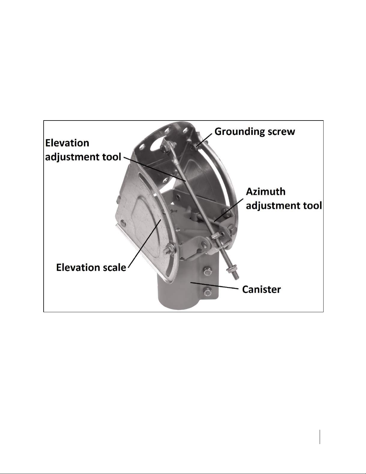
Az/El mount assembly
The Az/El mount assembly, shown in Figure 4, includes components that allow you
to adjust the antenna elevation and azimuth—the Az/El canister, the elevation
scale, and the azimuth and elevation adjustment tools. It also includes a grounding
screw, used to ground the assembly to the grounding block.
The Az/El canister supports the antenna and secures it to the mast. The elevation
scale is used to measure the angle of antenna elevation. The azimuth and elevation
adjustment tools are used to finely adjust the azimuth and elevation of the reflector
during antenna pointing.
Figure 4: Az/El mount assembly


Chapter 2 • Antenna Assembly parts and recommended tools
1042161-0001 Revision A
15
Antenna reflector
The antenna reflector shown in Figure 6 focuses the transmitted and received RF
signals. It attaches to the reflector bracket.
Figure 6: Antenna reflector
Handle the antenna reflector with care to avoid bending it or causing other
damage.

16
Chapter 2 • Antenna Assembly parts and recommended tools
1042161-0001 Revision A
Feed support arm
Figure 7 shows the feed support arm, before assembly, which supports the radio
assembly and feed horn.
Figure 7: Feed support arm with hardware
Feed Horn
Figure 8 Shows the feed horn.
Figure 8: Feed horn

Chapter 2 • Antenna Assembly parts and recommended tools
1042161-0001 Revision A
17
Small hardware parts list
Table 1 lists the small hardware parts included with the antenna kit.
Table 1: Small hardware parts
Hardware parts
Quantity
Listed parts are used to
attach…
Illustration showing
where parts are used
516
⁄inch × 34
⁄inch carriage bolts
5
Reflector bracket to Az/El
mount assembly
Figure 10 on page 23
516
⁄inch hex flange nuts
5
516
⁄inch × 34
⁄inch carriage bolts
5
Antenna reflector to
reflector bracket
Figure 13 on page 25
516
⁄inch hex flange nuts
5
516
⁄-18 × 2-14
⁄inch hex bolts
2
Installing the feed arm
Figure 14 on page 26
516
⁄-18 carriage bolts
1
516
⁄-18 flat washers
5
516
⁄-18 hex nylock nut
3
Boom arm plate
1
Feed Horn Screws
4
Installing the feed Horn
Figure 19: Attaching the
feedhorn and radio
assemblyFigure 19 on page 33
Feed Horn Split Lock Washers
4
Feed Horn Gasket
1
Radio assembly
The radio assembly shown in Figure 9 consists of the radio transmitter/receiver and
waveguide adapter. This can be dual or single-IFL.
Note: The radio assembly is shipped separately from the rest of the antenna and
may not arrive at the same time.

18
Chapter 2 • Antenna Assembly parts and recommended tools
1042161-0001 Revision A
Figure 9: Radio assembly
Table 2: Radio assembly part numbers
Part number
Model name
Type
Description
1504363-0001
Radio Assy, 2W, Single-IFL, Univ, 4M
Pure type
Single IFL
1503927-0003
Assy, Radio, Ku Band Universal
Pure type
Dual IFL

• Antenna Assembly parts and recommended tools
1042161-0001 Revision A
19
Tools
Table 3 lists the tools recommended for assembling and installing the antenna.
Table 3: Required tools
Tools
Details
Socket wrench, 12
⁄inch
(with 3 inch extension)
For 516
⁄inch bolts.
Open-end wrench, 12
⁄inch
For 516
⁄inch bolts. Two of the Az/El canister nuts are not
accessible by socket wrench. Some nuts and bolts require a
second wrench to prevent turning.
2 open-end or socket wrenches, 716
⁄inch
For 14
⁄inch bolts. Some nuts and bolts require a second wrench
to prevent turning.
Torque wrench, foot-pounds
With 12
⁄inch and 716
⁄inch sockets, capable of measuring torque
to 8 ft-lb.
Torque wrench, open-end, inch-pounds
716
⁄inch, capable of tightening to 20 inch-lb, such as the Ripley
model TW 207-AH-B torque wrench, which is present to 20 inch-
lb. Used to connect IFL to the radio assembly or ground block.
3 mm ball-end hex wrench
For Allen screws on polarizer assembly (for adjusting circular
polarization only).
Phillips-head screwdriver, 14
⁄inch
For screw used to secure antenna reflector to reflector bracket.
Bubble level
Used to ensure that the mast is plumb.
Compass
Used in determining proper antenna azimuth.
Dielectric grease
Used to prevent moisture contamination from occurring on
coaxial cable connections.
Weatherproofing tape
Used to keep moisture away from cable connections.
Approved RG6 cable
Used for IFL between satellite modem and antenna.
UV-rated cable ties
Used to secure slack in cables to antenna mast.

20
Chapter 3 • Installing the antenna and radio
1042161-0001 Revision A
Chapter 3
Installing the antenna and radio
This chapter explains how to assemble and install the antenna, radio assembly, and
associated hardware.
Before you install the antenna, read all safety information in Understanding
safety alert messages on page 5.
General instructions for assembling the antenna
If you work on a roof, tower, or other high structure, or use a ladder or
scaffold to access the work site, follow these precautions to prevent personal
injury or death:
•Walk only on sound roof structures.
•Ensure that the antenna assembly and installation surface are structurally
sound so they can support all loads (equipment weight, ice, and wind).
•Use safety equipment (e.g., a lifeline) appropriate for the work location.
•Follow all manufacturer safety precautions for all safety and other
equipment used.
•Perform as many procedures as possible on the ground.
•To avoid electric shock, stay at least 20 ft away from power lines when
there is a chance that you or the equipment you are using could
accidentally come into contact with the power lines. Always look up and
check for overhead lines before moving a ladder.
•If any part of the antenna or mount assembly comes in contact with a
power line, call the local power company to remove it. Do not try to
remove it yourself. If the antenna reflector contacts electric power lines,
you may be killed or seriously injured.
•For pole mount installations, be sure to obtain information regarding
underground utilities in the proposed location before digging.
•Call a local company that marks underground utility lines before digging to
avoid striking underground cables, pipes, or electric lines. Call 811 from
anywhere in the United States to contact a local company that does this.
You can also visit http://call811.com/.
Table of contents
Other EchoStar Antenna manuals


