Majestic SATPOS20 Instruction Manual

Installation & User Manual
SATPOS20
Mobile Dome Positioner Antenna

This manual contains important product information
on the use and maintenance of your SATPOS10
Dome Positioner satellite system. Please refer this
manual for installation, operation, maintenance and
contact information. Prior to contacting the manu-
facturer or dealer, have this manual and serial num-
ber available for reference.
ELECTRICAL HAZARD WARNING
THE COAXIAL CABLE THAT CONNECTS
THE OUTDOOR ANTENNA CARRIES
ELECTRICAL CURRENT.
EXERCISE EXTREME CAUTION WHEN
HANDLING THIS CABLE. DO NOT CUT,
BREAK OR SPLICE THIS LINE. DO NOT
INSERT OR CONNECT ANY DEVICES
SUCH AS SPLITTERS OR ANY OTHER
DEVICE FOR ANY REASON. THIS LINE IS
NOT COMPATIBLE WITH ANY OTHER
EQUIPMENT. DAMAGE WILL OCCUR TO
ANY DEVICE OTHER THAN THE SATPOS10
OUTDOOR ANTENNA IF
CONNECTED TO THE ANTENNA PORT.
2
SATPOS20

3
Table of Contents
1 Introduction
1.1 SATPOS20 System Overview
1.2 System Compatibility
1.3 Direct Broadcast Satellite Overview
1.4 Line of Sight (LOS) Interruption
1.5 System Components
2 Installation
2.1 Unpacking the SATPOS20
2.2 Antenna Installation
3 Operation
3.1 Operating the SATPOS20
3.2 The Satellite Acquisition with the SATPOS20
system
4 Troubleshooting
4.1 Causes and Remedies for Operational Issues
5 Maintenance
Majestic Global NZ Ltd.

A complete satellite TV system, illustrated in Figure 1-1, includes the
SATPOS20 antenna connected to a control box (IDU), a satellite TV
receiver, and a television set.
1.1 SATPOS-20 System Overview
Figure 1-1
4
SATPOS20
1 Introduction
The SATPOS20 satellite system is the innovative and a technologically
advanced satellite Dome Positioner system. The SATPOS20 has a
unique combination of state-of-the art components with the most
sophisticated satellite acquisition and tracking programs to provide the
following features:
■Fast satellite acquisition
■Compatible with any Satellite Receiver
■Compatible with all Direct Broadcast Satellites (DBS)
■Built-in Digital Broadcast Receiver (DVB)
■Capable of High Definition receiving
Coax Antenna Cable
(White)
Supplied 10 metres
Coax Cable
(White)
Supplied 1 metre

1.2 System Compatibility
1.3 Direct Broadcast Satellite Overview
Direct Broadcast Service (DBS) satellites broadcast audio, video and
data information from satellites located 22,000 miles in space. A
receiving station, such as the SATPOS20, should include a dish and
satellite receiver to receive the signals and process them for use by the
consumer audio and video equipment. The system requires a clear
view of the satellite in the sky to maximize the signal reception.
Figure 1-2
Majestic Global NZ Ltd.
The SATPOS20 satellite antenna is fully compatible with Digital Video
Broadcasting (DVB) satellites, as well as OPTUS D1 satellite. At
present, there is one Direct Broadcast Satellite position over New
Zealand.
5

1.4 Line of Sight (LOS) Interruption
The SATPOS20 needs a clear line of sight (LOS), view to the satellite
for uninterrupted reception. Objects such as tall buildings, bridges,
tunnels and trees that block this view will cause a loss of signal. The
signal will be quickly restored once the antenna has a clear line of sight
again.
Heavy rain, cloud, snow or ice may also interfere with the signal
reception quality. If the satellite signal is lost due to blockage or severe
weather condition, services from the receiver will be lost (picture will
freeze frame and may disappear). When the satellite signal strength is
again high enough, then the receiver will resume providing desired
programming services.
1.5 System Components
The standard SATPOS20 antenna system consists of the Outdoor Unit
(ODU, dome antenna), the Indoor Unit (IDU), including Power Supply.
SATPOS20 Outdoor Unit (ODU):
The Outdoor Unit houses the electronics, dish, LNB within a radome.
SATPOS20
Figure 1-3
6

SATPOS20 Outdoor Unit (Inside):
Majestic Global NZ Ltd.
SATPOS20 Indoor Unit (IDU):
The IDU supplies power and commands to the SATPOS20. This device
allows for selection of the satellite from which you wish to receive a
signal.
Figure 1-4
Figure 1-5
7

This section offers a general explanation of how properly to install the
SATPOS20 antenna. Installation of the SATPOS20 must be accomplished by or
under the supervision of an authorized dealer for the Limited Warranty to be
valid and in force. The steps in the installation and setup process are as
follows:
1. Preparing for the installation
2. Select location
■Mount the antenna (ODU) on top of the vehicle
3. Equipment and cable installation
■Install the Indoor Unit (IDU), Power Supply near the Satellite
Receiver and TV
■Connect the cables
4. Initial power-up and system checkout
■Select the satellite
2.1 Unpacking the SATPOS20
The following items are included in the packaging of the SATPOS20:
Be sure to verify the complete shipment of your system before
beginning the installation.
2 Installation
SATPOS20
8
Item Description Quantity
1Outdoor Antenna Assembly (ODU) 1 each
2Indoor Unit (IDU) 1 each
3Power Cable 1 each
4Coax Cable (10m) 1 each
5Coax Cable (1m) 1 each
6Installation & User Manual 1 set
2.1.1 Preparing the SATPOS20 Antenna for Installation
Upon opening the shipping container remove the items listed in the
table above

2.1.2 Installation Tools and Materials
The SATPOS20 system is designed for simple installation and setup.
However, the following list of equipment or items should be available
during installation of the SATPOS20:
■Electric drill and drill bits (Define the size?) eg. 5mm & 2mm
■Philips and flat tip screwdrivers (Define the size?) eg. #2 & #0
■Socket wrench
■Silicon sealant
■Fastener suitable for specific application
2.2 Antenna Installation
2.2.1 Select Location
Perform a through site inspection on the roof for the antenna to be mounted.
1. The antenna must have a clear view of the sky and horizon at all the
direction to avoid blockage of the satellite signal.
2. The antenna should be on the centerline of the vehicle.
3. The antenna should be mounted on as level a surface as possible.
4. Initial power-up and system checkout
5. Using two people, place the antenna onto the roof. Do not try to install
the antenna by yourself.
■Now that the location has been determined, place the antenna in
its final desired location.
■Make sure that it is the centerline of the vehicle
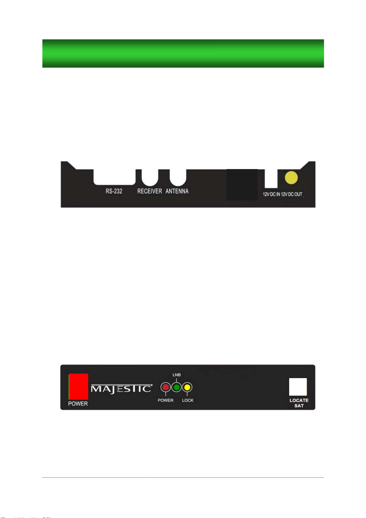
2.2.2 Equipment and cable installation
This offers a general explanation of how to install the Indoor Unit and
satellite receiver properly to the inside of vehicle connecting with coax
cable.
1. The RF cable is routed from the antenna to the IDU inside the
vehicle.
2. Once decide where to place the IDU and satellite receiver, and
make sure that both units are placed in a dry and protected area.
3. The IDU and satellite receiver should be placed away from any
heat source and in an area with proper ventilation.
SATPOS20
9

4. Ensure that there are at least 3cm of space around both units
for ventilation and connection of cables.
Do not stack the units on top of each other.
5.The following describes the basic wiring configurations for the
SATPOS20 antenna system.
■Connect the RF cable to the SATPOS20 port on the back of
the IDU
■Connect one end of the supplied coax cable to the receiver
2.2.3 Initial power-up and system checkout
Once all of the system cables have been connected, and when the
Power Supply is connected to the IDU then the antenna will have power
applied and it should be ready to checkout the system.
The light indicators on the IDU have three different modes of operation.
■When the POWER LED is lit, it indicates that the IDU is
turned on and tracking the satellite
■The LNB indicator lights up when your decoder is powering
the LNB
■When the antenna acquires the desired satellite, the LOCK
LED light is turned on
Figure 2-1
Majestic Global NZ Ltd.
10
Power can be turned off by pressing the POWER button as shown in Figure 2-2
Figure 2-2

SATPOS20
11
Make sure that the television is on and set for the correct video input
source from the receiver:
■Turn on the power switch of the IDU, satellite receiver and
TV/monitor.
■Ensure the Green “LNB” LED is lit.
■The next step is pressing LOCATE SAT button. This action is
to search the satellite and to make the satellite acquisition.
The Red Power come on whilst the unit is tracking to the
satellite.
■Once satellite is acquired and secured, the LOCK light will
come on.
■The Unit can be turned off at this stage, once the unit has
locked onto the satellite.

3.1 Operating the SATPOS20
3.2 The Satellite Acquisition with the SATPOS20 system
■Turn on the power to the TV and satellite receiver
■Turn on the receiver using the POWER switch
☺Under normal conditions, the SATPOS20 will acquire the correct
satellite and produce television programming in less than 1 minute.
To minimize the time it takes the antenna system acquiring the
satellite, do not change the channel during the startup process.
3.2.1 Power on
3.2.2 Changing Channels
If you have followed the installation instructions, your system should be set to
the satellite of your choice and the system should have downloaded the
appropriate channel guides. When the SATPOS20 system and satellite
receiver is properly configured, it is easy to change the channel using the
remote control that normally comes with the receiver unit.
3.2.3 Watching TV at stationary location
The SATPOS20 is designed to operate as efficiently and as reliably as possible
when the vehicle is parked. It is also the quickest satellite acquisition system
available among the Dome Positioner antennas. After parking the vehicle and
confirming that the antenna is receiving the satellite signal, you may turn off
the IDU to avoid unnecessary use of power. Because the LNB receives its
power from the ODU, and the antenna will continue to receive the satellite TV
signals and relay them to the receiver.
Majestic Global NZ Ltd.
12
3 Operation
3.2.3 Memorizing the satellite position
Your new SATPOS20 system has a built-in function that remembers the posi-
tion of satellite which has been tracked and acquired. If you move a vehicle
from the location where you have watched satellite TV programs, pressing Sat
Locate button will make satellite acquisition fast without the full search.
The SATPOS20 system is easy to use.
Under normal conditions, operation of the SATPOS20 requires no
intervention from the user. Antenna unit initialization and satellite
acquisition is completely automatic.
The vehicle should be stationary for start-up and watch TV.

4.1 Causes and Remedies for Operational Issues
4.1.1 System Not Power-On
4.1.2 Improper Wiring
■Check the system is properly wired
■Verify that the IDU, ODU, and receiver units are properly connected
■Check the antenna unit cable connections with proper RF connectors
■Check the satellite trying to acquire
■Select receiver menu, set the correct LNB frequency setting
■Check the LNB skew angle
4.1.3 Incorrect Satellite or LNB Configuration
■Move the vehicle to clear location from obstruction
■Check the satellite coverage area
Satellite signals can be blocked by trees and buildings, over-
passes, underpasses or obstructive equipments on the vehicle.
4.1.4 Search Failure
SATPOS20
4 Troubleshooting
There are a number of common issues that can affect the signal quality and/
or the operation of the SATPOS20 antenna system. The following sections
address these issues and potential solutions.
■Verify that the Indoor Unit (IDU) and receiver are powered on
■Check the blown fuses
■Verify vehicle battery has been connected properly
13
4.1.5 Snow, Rain or Dew pooling on Dome
■Check the satellite trying to acquire—Optus D1
■Wipe and clean the outside of the Dome if heavy water droplets are
present. Droplets will adhere to a dirty surface and create a barrier
■Check the drain holes in the base are free and clear.

Majestic Global NZ Ltd.
14
■Check cable connections and plugs from the Dish to the IDU Black
Box and to the Receiver (decoder). Make sure these are tight and
secure.
■If problem is till present call Majestic Auckland Office to speak with
our Technical Support Person 09 415 6936
■Majestic Office can also direct you to our nearest Service Agent
4.1.7 Flashing ‘Power LED & Lock LED’ on IDU Black Box
■Check the satellite trying to acquire
■Select receiver menu, set the correct LNB frequency setting
■Check the LNB skew angle
4.1.6 Satellite Receiver
4.1.8 Flashing LED—all three (Communication Error)
■Double check cable connections and plugs from the Dish to the IDU
Black Box and to the Receiver (decoder). Make sure these are tight
and secure.
■If problem is till present call Majestic Auckland Office to speak with
our Technical Support Person 09 415 6936
■Majestic Office can also direct you to our nearest Service Agent
4.1.9 No Signal or ‘Rain Fade’ showing on TV but the Green
and Orange LED on IDU (Black Box) are ON
■Check that the Digital Decoder is turned ON
■Check cable connections between Decoder and IDU to the Dish
■Check the Satellite parameter settings in your decoder
1. Satellite Name—Optus D1
2. Decoder LNB Settings for — Freeview = 11300 and SKY = 10750
3. Transponder Frequency—Refer to your Decoder Manual
■If problem is till present call Majestic Auckland Office to speak with
our Technical Support Person 09 415 6936
■Majestic Office can also direct you to our nearest Service Agent

SATPOS20
15
5 Maintenance
The SATPOS20 Satellite System has been designed to be maintenance
and trouble free. For optimum signal strength, keep the dome clean
from dirt, bugs, and other debris. Periodic washing and cleaning of the
dome with mild soap and water is recommended.
If you have any comments or questions, please contact the Majestic
Service Department.

Majestic Global NZ Ltd.
Appendix A - System Specification
16
Frequency Band Ku Band
Operating Frequency 12.25GHz ~ 12.75GHz
LNB Local Frequency 11.3GHz
Dish Diameter 60cm
Radome Diameter 70cm
Radome Height 38cm
Antenna Weight 12kg
Antenna Gain 32dBi
Polarization Type V/H
Stabilization Type 2-Axis DC Motor
Elevation Range 15° ~ 62°(selectable)
Tracking Rate <50°/sec
Azimuth Range 370°
Temp Range -22°C ~ 55°C
Humidity 95%@40°C
Power [email protected](Max)
Target Satellite Optus D1

SATPOS20
17
Appendix B - Glossary
Azimuth: The horizontal angle of observer’s bearing measured clock-
wise from a reference direction. It is circular rotation around
the vehicle hereby.
Elevation: Angle in degrees measured from the ground level.
Signal Strength: Intensity of electronic signal received from the satel-
lite transmission.

Majestic Global NZ Ltd.
Limited Product Warranty
Majestic warrants the SATPOS20 product purchased against defects in
materials for a period of ONE (1) years and against labour costs for a
period of ONE (1) year from the date of original retail purchase by the
original purchase. It is the customer’s responsibility to verify the date
of purchase returning the warranty card included with the product to
Majestic within 30 days of purchase, or by providing a dated sales
receipt for the Majestic product under warranty with the warranty
claim. If this date cannot be verified, the warranty period will begin
30days after the date of manufacture of the original product purchased.
If you discover a defect, Majestic will, at its option, replace or repair
the product at no charge to you, provided you return it during the
warranty period. Please attach your name, address, telephone
number, a description of the problem and a copy of sales receipt as
proof of date of original retail purchase, to each product returned to
warranty service. Alternatively, you may bring the product to an
Authorized Majestic dealer/distributor for repair. If the product was
installed by an Authorized Majestic dealer/distributor, Majestic will
cover the dealer’s/distributor’s labour charges for warranty repairs,
provided that the dealer/distributor contacts Majestic for pre-approval
of the charges.
This Limited Warranty does not apply if the product has been damaged
by accident, abuse, misuse or misapplication or has been modified
without the written permission of Majestic; if the unit has not been
installed by an authorized installer; if any Majestic serial
number has been removed or defaced; or if any factory-sealed part of
the system has been opened without authorization.
THE EXPRESS WARRANTIES SET FORTH ABOVE ARE THE ONLY
WARRANTIES GIVEN BY MAJESTIC WITH RESPECT TO ANY PRODUCT
FURNISHED HEREUNDER; MAJESTIC MAKES NO OTHER WARRANTIES,
EXPRESSED, IMPLIED OR ARISING BY CUSTOM OR TRADE USAGE,
AND SPECIFICALLY DISCLAIMS ANY WARRANTY OF MERCHANTIBILITY
OR OF FITTNESS FOR A PARTICULAR PURPOSE, SAID EXPRESS
WARRANTIES SHALL NOT BE ENLARGED OR OTHERWISE AFFACTED BY
TECHNICAL OR OTHER ADVICE OR SERVICE PROVIDED BY MAJESTIC
18
Majestic Global NZ Ltd.

Majestic Global NZ Ltd.
19
Majestic Global NZ Ltd.
Table of contents
Other Majestic Antenna manuals
Popular Antenna manuals by other brands

Televes
Televes 800 user manual

Avocent
Avocent Emerge HGA51G-DIR30 Quick installation guide

Comtek
Comtek COM-20VA instructions

Atomic
Atomic ANTENNAE CHANDELIER installation instructions

Andrew
Andrew Grid Sectional Parabolic Antennas Specifications

Chameleon Antenna
Chameleon Antenna Antenna Spoke Base Series user guide