Ecleree AC-6 User manual

USER MANUAL
MANUAL DE INSTRUCCIONES
NOTICE D'UTILISATION
BEDIENUNGSANLEITUNG


3
INSTRUCTION MANUAL
1. IMPORTANT REMARK 04
1.1. Safety Precautions 04
2. INTRODUCTION 04
3. INSTALLATION 05
3.1. Placement and mounting 05
3.2. Connectable Signal Sources 05
4. OPERATION AND USE 06
4.1. Start up 06
4.2. Monitoring 06
4.3. Channel gain and equalization 06
4.4. Sending to external effects units, AUX SEND 07
4.5. Using the XFADER 07
4.6. TALKOVER 07
4.7. Outputs 08
5. CONSIDERATIONS 09
5.1. Ground loops, background noise 09
5.2. Cleaning 09
6. FUNCTION LIST 10
7. FUNCTION DIAGRAM 11
8. TECHNICAL CHARACTERISTICS 36
9. CONFIGURATION DIAGRAM 37
10. BLOCK DIAGRAM 38
All numbers subject to variation due to production tolerances. ECLER SA reserves the right to make changes or
improvements in manufacturing or design which may affect specifications.

4
1. IMPORTANT REMARK
We thank you for trusting on us and choosing our AC-6 mixer. In order to get the most in operation
and efficiency from your mixing unit, it is VERY IMPORTANT for you -before you plug anything -to read
this manual very carefully and take seriously into account all considerations specified within it.
In order to guarantee the optimum operation of this unit, we strongly recommend that its
maintenance be carried out by our Authorised Technical Services.
1.1. Safety Precautions
This apparatus must be earthed through its mains cable.
Do not expose the unit to rain or water splashes, and do not place liquid containers or
incandescent objects like candles on top of the unit. Do not obstruct the ventilation shafts
with any kind of material.
Any change in the configuration of the unit must be carried out by a qualified technician. Should
any connection / disconnection task be done, always disconnect the unit from the mains supply.
There are no user serviceable parts inside the unit.
2. INTRODUCTION
With the AC-6, ECLER comes back to the historical AC series. In 1974, the AC-4 set the
precedents to what later on would become the club mixer with sliding faders.
During many years, the AC-4 has been praised as one of the best sounding mixers that ECLER
has ever launched during its long career. The AC-6 gathers the AC-4’s “essence” adding the latest
mixing technology advancements, turning this unit into an unrivalled mixer.
The AC-6 has 6 mixable channels, i.e. 6 channels with conventional sliding fader plus one special
channel for the effect return with rotary potentiometer, which can be used to input normal line-level signals
from any source. It features 20 stereo inputs: 4 PHONO, 6 CD (high line level for compact disc, DAT, MP3
players), 6 LINE, 1 AUX RETURN, 1 MIX; plus 2 more MICRO inputs for balanced microphones.
All channels have a lever switch input selector, independent gain control and 3-band tone
controls. The AC-6 incorporates an XFADER potentiometer, assignable to any input using a lever
switch.
All inputs are PFL-capable in order to visually (through the VU meters) and acoustically (through
headphones) monitor any signal connected to the inputs of the unit.
In the AC-6, we have cared specially about the roughness, long-time response and maximum
adaptability to the DJ needs, getting a total ease of operation.

5
3. INSTALLATION
3.1. Placement and mounting
The main consideration that has to be taken when searching a location for the AC-6 mixer is the
maximum working comfort for the operator, allowing to realize the connections as easy as possible.
The AC-6 has 19" (482,6mm), 8U (355mm) rack mounting ears that allow you to place it in a
standard rack.
Because of the high gain of the PHONO and MICRO inputs, the mixer must be placed as far as
possible from noise sources (dimmers, engines, etc.) as well as from any mains cable. You should
never, under any circumstance, remove the metallic cover of the mixer.
The AC-6, being a low consumption unit, does not need any cooling; you should anyway avoid
exposure to extreme temperatures and the operating environment must be as dry and dust free as
possible.
The AC-6 operates under voltages between 90 and 264 V at 47 to 63 Hz. This device features an
over dimensioned power supply that adapts to the mains voltage in any country of the world with no
need to make any adjustments.
In order to protect the mixer from eventual mains overloads, it has a time-lag 0,5 A mains
protection fuse. Should this fuse ever blow off, disconnect the mixer from mains and replace it with an
identical one.
NEVER REPLACE THE FUSE WITH ANOTHER ONE WITH A HIGHER VALUE.
ATTENTION: Changing the fuse must be performed by qualified technical personnel.
3.2. Connectable Signal Sources
-Turntables / Phono: They must be fitted with a magnetic cartridge with nominal output level
between -55dBV and -25dBV (1,77 to 56mV). The PHONO (55) inputs of the AC-6 have a high
headroom (margin before saturation) and it can handle higher output cartridges than what is usual.
These inputs are supplied with a nominal input sensitivity of -40dBV (10mV).
-Microphones: The MIC inputs (54) are ready for a nominal input level of -50dBV (3,16 mV) and
are equipped with COMBO connectors. The COMBO connector provides both a XLR plug and a ¼’’
Jack in the same receptacle. The connection of balanced signals is as follows:
XLR-3¼‘’ Jack
Hot or direct signal >Pin 2 Tip
Cold or inverted signal >Pin 3 Ring
Ground >Pin 1 Sleeve
Low impedance (200 to 600Ω) monophonic microphones must be used. In case of working with
an unbalanced connection Pin 1 and Pin 3 must be short-circuited.
The AC-6 wears phantom power for condenser microphones. The 2 switches (53) to activate the
phantom power are independent for each micro and are located at the unit’s back plate. The phantom
voltage supplied is 18 VDC.
-CD/LINE Inputs. Given the important level differences between usual LINE and CD sources
(e.g. Tape decks), the AC-6 provides specialized inputs for each source. The sensitivity of the CD input
(52) is 0dBV (1V), while the LINE (51) sensitivity is -10dBV (316mV).
Compact disc, DAT, MP3, DVD Audio... should be connected to the CD input. Tape recorders,
cassettes, tuners, videos... should be connected to the LINE input.

6
-Headphones: In order to achieve the best performance, they should be high impedance type
(200-600Ω). They will be connected to the output “32” using normalized ¼’’ stereo jacks. Connect
ground to sleeve, ring to right and tip to left.
-Other mixers: The MIX (38) input provides a direct access to the main mix bus, so this is a
perfect input for another mixer to be plugged in without using up a regular input.
-Power amplifiers: See paragraph 4.7.
4. OPERATION AND USE
4.1. Start up
This is made using the POWER switch (17). Immediately the 3 green leds, identified as +5V,
+18V and -18V (16) will light up, advising that the different voltages that feed the mixer are working
properly. The 5V voltage is used for the VU-meter and the LED indicators. The symmetric 18V voltage
feeds the audio circuits. Although the noise generated by powering up the AC-6 is reduced to a bare
minimum and is nearly null with the MASTER (27, 33) faders down, it is always advisable not to forget
about this power-up sequence: sound sources, mixer, equalizers, active filters and power amplifiers.
Power down the equipment by following the inverse sequence. This way the peaks or transients
produced by powering up /down a device do not affect the following one in the audio chain and, as a
result, they do not reach the loudspeakers, which are the most vulnerable audio elements in this case.
4.2. Monitoring
The AC-6 wears a visual and auditory monitoring system with headphones and CUE outputs and
double VU-meter. By activating any of the PFL switches, the input signal/s can be heard through the
headphones and seen on the right VU-meter. The left VU-meter displays the mix signal or the signals
present on output 1 or output 2, depending on the position of the handle selector OUT1/MIX/OUT2 (20).
The rotating potentiometer PFL/MIX (28) allows mixing the selected PFL channels with the main
program MIX.
It is also possible to realize monitoring using the CUE output (37), which can be controlled with
the rotating potentiometer (26). This output is fed with the same signal that feeds the headphones
output and its nominal level is 0dBV (1V).
4.3. Channel gain and equalization
These controls allow adjusting the input sensitivity and tone levels individually for each channel.
With the GAIN control (4), the input gain fine adjustment, it is possible to match the signal levels
of the different channels. This adjustment can be realized using the left and right VU-meter and the
headphones and CUE outputs. The GAIN controls have a performance margin of ±15dB and the central
position corresponds to the nominal gain of the selected input.
The tone controls (5-6-7) of all channels provide a CUT of +10dB.

7
4.4. Sending to external effects units, AUX SEND
The AC-6’s 6 channels wear rotating potentiometers (11) which allow to send signals to an
external effects unit, sampler, delay, … These potentiometers dose the signal level which has to be sent
from each channel. The AUX SEND output (45) has to be connected to the input of the effects unit,
whose outputs can be connected either to the AUX RETURN input (46) or to any LINE input.
Using the PRE/POST switch (10), the send signal can be configured to be influenced or not by
the channel’s fader.
The AC-6 also wears the AUX SEND (25) and AUX RETURN (36) potentiometers, which allow
adjusting the main send and returning levels. Furthermore, the mixer has a PFL switch for the AUX
RETURN signal.
4.5. Using the XFADER
The AC-6 wears a sliding, short-distance, horizontally displayed potentiometer. This
potentiometer, called XFADER (34), is able to make direct transitions between the signals present at
any of the channels. This allows the DJ to prepare his mixes and switch from one signal to another just
using the XFADER.
The AC-6 wears the “XF SHAPE” potentiometer (35) to adjust the XFADER’s curve, which allows
to make soft fades between musical tracks or fast and short scratch-like fades.
A handle selector with three positions (12) located under the PFL switch allows to assign any
input to the position A or B of the XFADER. If the XFADER’s position “OFF” is selected, the signal goes
directly to the main mixing bus.
The AC-6 XFADER wears an electronic VCA circuit which increases considerably the life span.
4.6. Talkover
Using the MIC 5 (15) and MIC 6 (22) buttons, the talkover function is activated for the channels 5
and 6, reducing automatically the level of the signals present on the other channels. This happens when
the DJ or the speaker begins to talk into the connected micro. When the speaker stops talking, the
original volume is gradually recovered.
The ATT potentiometer (19) allows to control the attenuation level of the main signal (between 0
and 30dB) and with the TIME knob (18) the release time is controlled, which is the time necessary to
return progressively to the original level (between 0,5 and 2 seconds).

8
4.7. Outputs
The AC-6 mixer has two independent outputs, OUT1 and OUT2. Each one has its own volume
control, with a sliding fader for OUT1 (33), and a rotary one for the OUT2 (27). Both have a common
balance control BAL (24).
You must be careful when setting up the general output level of the mixer. The "clip" display of
the connected power amplifiers must never remain permanently lit, but do it only occasionally by
following the rhythm of the bass signals that are being played.
The AC-6 mixing unit is factory adjusted at 0dBV/1V, although these outputs can be internally
modified to +6dBV/2V. See configuration diagram.
Both outputs OUT1 (40-41) and OUT2 (42-43) are balanced or symmetric and the pin out is the
following:
Hot or direct signal >Pin 2
Cold or inverted signal >Pin 3
Ground >Pin 1
The balanced circuit simulates an output transformer, so if you wish to use OUT1 and OUT2 in
non-balanced mode, you should short circuit the unused pin to ground. Otherwise, the signal will not
have an appropriate level and quality.
The AC-6 has two recording outputs: REC A (47) and REC B (48). The REC A output offers the
direct program signal, which is not affected by the talkover and L+R controls. The signal provided by
REC B output, however, is affected by these controls.
The CUE output (37) allows monitoring using an external amplification system. The signal provided
by this output is the same as the signal offered by the headphones output, but it has an independent
volume control.
Finally, it is necessary to emphasize the existence of the L+R switch (29), which turns the stereo
signal into a mono signal or hands in just one of the channels. This switch affects the outputs OUT1, OUT2
and REC B and can also affect the CUE and headphones output, if “MIX” is selected.

9
5. CONSIDERATIONS
5.1. Ground loops, background noise
Please make sure that the signal sources that arrive to the mixer and the devices connected to
its outputs have separated grounds, so that every device has just one possible ground connection,
which avoids the generation of hum, that could even degrade the quality of the sound playback.
If the cable’s shields are connected to the chassis, they cannot be connected among each other
in order to avoid creation of ground loops.
The AC-6 mixer has been designed to obtain the lowest possible background noise. However,
independently of the electronic conception, the background noise depends directly on the correct
installation and manipulation of the mixing unit.
It is not the same, having a channel FADER at level “2” and the MASTER at level “10” or vice
versa. In the first case, the signal that arrives to the mixing amplifier and has a certain noise level, is
weak, so that the signal/noise ratio is low (poor signal). When the output amplifier raises the level of this
signal, the noise level obtained at the output will be high. In the second case, having the FADER to
maximum, the signal level which arrives to the mixing amplifier is high and therefore the signal/noise
ratio is also high, so that the output signal will maintain a better ratio than in the first case.
5.2. Cleaning
The control panel should never be cleaned with solvent or abrasive substances as it could
become damaged. To clean it, use a slightly moist soft cloth, together with a neutral liquid detergent,
and then dry it with a clean cloth. It is advisable to remove all sweat stains after use. Be careful to
ensure that water never enters the machine through any of the openings.

10
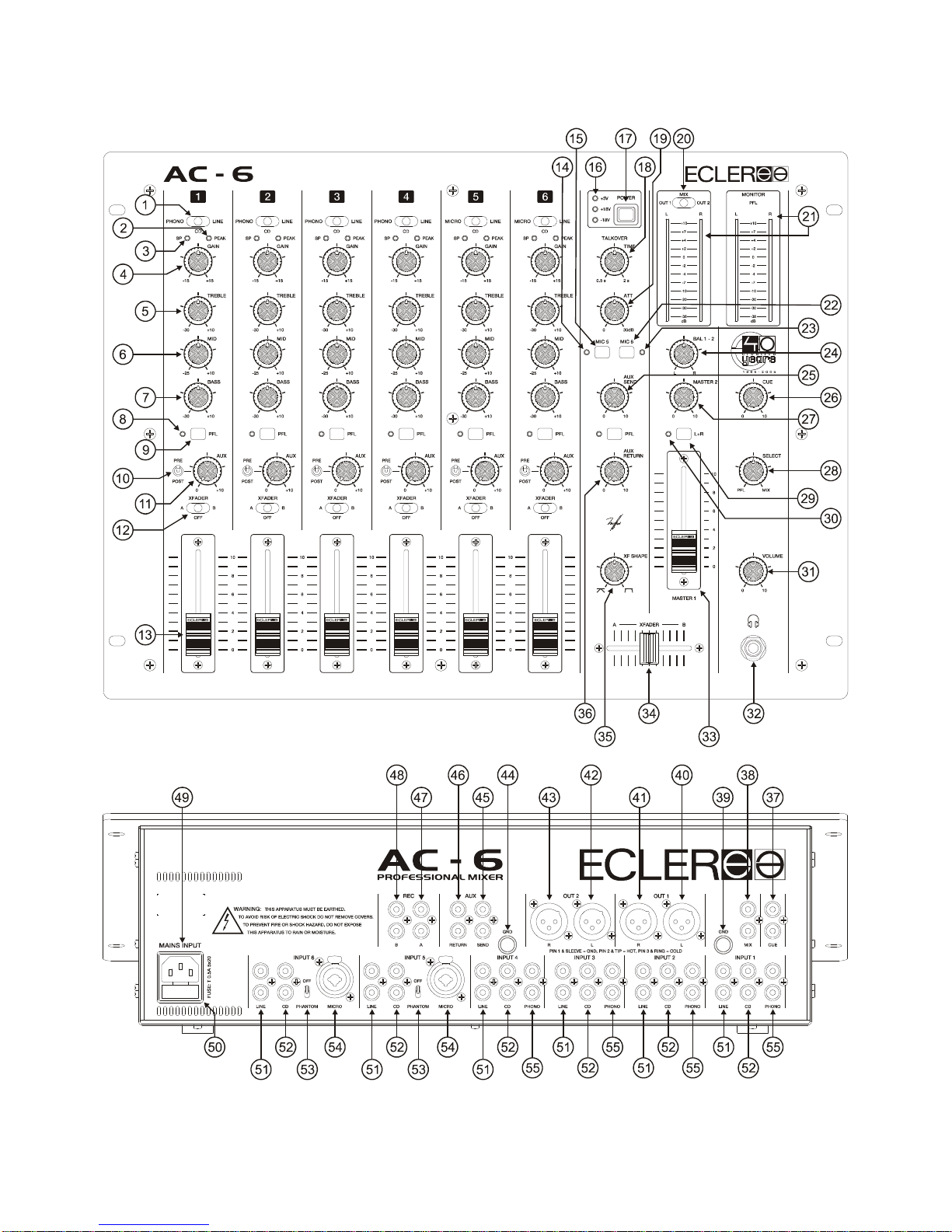
6. FUNCTION LIST
1. Input selector
2. Peak level indicator, PEAK
3. Signal present indicator, SP
4. Input sensitivity adjust, GAIN
5. Treble control, TREBLE
6. Midrange control, MID
7. Bass control, BASS
8. LED indicator, PFL
9. Prefader listening control, PFL
10. Pre-or post-fader switch for auxiliary send, PRE / POST
11. Auxiliary send control, AUX
12. Send to XFADER switch, XFA/MIX/XFB
13. Channel gain
14. LED indicator, MIC5
15. Talkover on, MIC 5
16. Visual display LEDs, +5/+18/-18V
17. Mains off/on Switcher, POWER
18. Talkover Recovery time control, TIME
19. Talkover effect control, ATT
20. VU-meter display switch, OUT1/MIX/OUT2
21. LED VU Meter
22. Talkover on, MIC 6
23. LED indicator, MIC 6
24. Balance control, BAL 1 -2
25. Main auxiliary send control, AUX SEND
26. Cue volume control, CUE
27. Volume control OUT 2, MASTER 2
28. PFL/MIX monitoring crossfade, SELECT
29. Left and Right signal sum, L+R
30. LED indicator, L+R
31. Headphones volume control, VOLUME
32. Stereo jack headphones
33. Volume control OUT 1, MASTER 1
34. Crossfader control, XFADER
35. Crossfader Shape adjuster, XF SHAPE
36. Auxiliary return level, AUX RETURN
37. Cue output, CUE
38. Mix input, MIX
39. Ground pin, GND
40. Left channel balanced output, OUT 1 L
41. Right channel balanced output, OUT 1 R
42. Left channel balanced output, OUT 2 L
43. Right channel balanced output, OUT 2 R
44. Ground pin, GND
45. External auxiliary send output, AUX SEND
46. External auxiliary return input, AUX RETURN
47. Recording RCA connector, REC A
48. Recording RCA connector, REC B
49. Mains socket
50. Fuse holder
51. Line input, LINE
52. CD input, CD
53. Phantom switch, PHANTOM
54. Microphone balanced input, MICRO
55. Phono input, PHONO
11
7. FUNCTION DIAGRAM

12
MANUAL DE INSTRUCCIONES
1. NOTA IMPORTANTE 13
1.1. Precauciones 13
2. INTRODUCCIÓN 13
3. INSTALACIÓN 14
3.1. Ubicación y montaje 14
3.2. Fuentes de señal conectables 14
4. OPERACIÓN Y USO 15
4.1. Puesta en funcionamiento 15
4.2. Monitoraje 15
4.3. Ganancia y ecualización de vía 15
4.4. Envío a unidades exteriores de efectos, AUX SEND 16
4.5. Utilización del XFADER 16
4.6. TALKOVER 16
4.7. Salidas 16
5. CONSIDERACIONES 17
5.1. Bucles de masa, ruido de fondo 17
5.2. Limpieza 17
6. LISTA DE FUNCIONES 18
7. DIAGRAMA DE FUNCIONES 19
8. CARACTERÍSTICAS TÉCNICAS 36
9. DIAGRAMA DE CONFIGURACIÓN 37
10. DIAGRAMA DE BLOQUES 38
Todos los datos están sujetos a variación debida a tolerancias de producción. ECLER S.A. se reserva el derecho de
realizar cambios o mejoras en la fabricación o diseño que pudieran afectar las especificaciones.
13
1. NOTA IMPORTANTE
Agradecemos su confianza por haber elegido nuestro mezclador AC-6. Para conseguir la máxima
operatividad y rendimiento de su mesa de mezclas es MUY IMPORTANTE antes de su conexión leer
detenidamente y tener muy presentes las consideraciones que en este manual se especifican.
Para garantizar el óptimo funcionamiento de este aparato recomendamos que su mantenimiento
sea llevado a cabo por nuestros Servicios Técnicos autorizados.
1.1. Precauciones
Este aparato debe ser conectado a tierra mediante su cable de alimentación.
No exponga el aparato a la caída de agua o salpicaduras, no ponga encima objetos con
líquido ni fuentes de llama desnuda, como velas. No obstruya los orificios de ventilación con
ningún tipo de material.
Cualquier cambio en la configuración debe ser realizado por personal técnico cualificado.
En caso de requerir alguna intervención y/o conexión desconexión del aparato debe
desconectarse previamente de la alimentación.
En el interior del aparato no existen elementos manipulables por el usuario.
2. INTRODUCCIÓN
Con el AC-6 ECLER recupera la referencia histórica AC. En 1974 el AC-4 sentó los precedentes
de lo que sería el mezclador de club con faders deslizantes.
Durante años el AC-4 ha sido elogiado como uno de los mezcladores con mejor sonido que
ECLER ha lanzado en su larga singladura. El AC-6 recoge la “esencia” del AC-4 incorporando los
últimos avances en tecnología de la mezcla, convirtiendo posiblemente esta unidad en un mixer
inigualable.
El AC-6 dispone de 6 vías mezclables; 6 canales con fader deslizante convencional y una vía
especial para retorno de efectos con fader rotativo a la que también puede conectársele cualquier señal
que entregue nivel de línea. Dispone de 20 entradas estereofónicas: 4 de PHONO, 6 de CD (líneas de
alto nivel para compact disc, DAT o reproductores de MP3), 6 de LINE, 1 de AUX RETURN, 1 de MIX;
más 2 de MICRO preparadas para micrófonos balanceados.
Todos los canales disponen de un selector de entradas de palanca, control de ganancia
independiente para cada una de las vías así como controles de tono de tres bandas. El AC-6 incorpora
un potenciómetro XFADER asignable a cualquiera de las entradas mediante un selector de palanca.
Todas las entradas disponen de la función PFL para monitorizar visualmente mediante el
VU-Metro y acústicamente mediante auriculares cualquier señal conectada a las entradas de la mesa.
En el AC-6 se ha cuidado por encima de todo la fiabilidad, dureza al paso del tiempo y la
máxima adaptabilidad a las necesidades del Disc-Jockey, consiguiendo de esta forma una total
comodidad de operación.

14
3. INSTALACIÓN
3.1. Ubicación y montaje
La principal consideración a tener en cuenta en el momento de buscar la ubicación del mezclador
AC-6 debe ser la máxima comodidad de trabajo del operador, permitiendo una total facilidad en la
realización de las conexiones.
El AC-6 permite ser montado en rack, dado su tamaño standard de 19" (482,6mm) y 8 unidades
(355mm) rack de altura.
Dada la elevada ganancia de las entradas de PHONO y de MICRO, debe procurarse situar el
mezclador lo más alejado posible de fuentes de ruido (variadores de tensión, motores, etc.), así como
de cualquier cable de red. Por esta misma razón y bajo ninguna circunstancia debe quitarse la tapa
metálica del aparato.
Gracias a su bajo consumo, el AC-6 no precisa ventilación. Sin embargo, debe evitarse que esté
expuesto a temperaturas extremas y que la atmósfera del local sea lo más seca y limpia de polvo
posible.
El AC-6 funciona con corriente alterna de 90 a 264V y de 47 a 63Hz. Este aparato equipa una
fuente de alimentación sobredimensionada capaz de adaptarse sin ningún tipo de ajuste a la tensión de
red de cualquier país del mundo.
Para protegerse de eventuales sobrecargas, el AC-6 está equipado con un fusible de red de 0,5A
temporizado. En el caso de que éste se fundiera se sustituiría por otro de idénticas características.
EN NINGÚN CASO DEBE PONERSE UN FUSIBLE DE VALOR MÁS ELEVADO.
PRECAUCIÓN: El cambio de fusibles debe ser realizado por personal técnico cualificado.
3.2. Fuentes de señal conectables
-Platos giradiscos: Deben ir equipados con cápsula magnética capaz de dar un nivel de salida
nominal entre -55 y -25dBV (1,77 y 56mV). Dado que las entradas de PHONO (55) del AC-6 tienen una
elevada capacidad de sobrecarga, puede admitir cápsulas de mayor nivel de salida. Estas entradas
tienen una sensibilidad nominal de -40dBV(10mV).
-Micrófonos: Las entradas de MICRO (54), están preparadas para un nivel nominal de entrada
de -50dBV (3.16mV). Los conectores de micrófono son del tipo “COMBO”. El conector COMBO
combina en un mismo conector la conexión tipo XLR-3 y la conexión tipo jack ¼”. Estas entradas
admiten la conexión en modo balanceado. Para ello se realizará la conexión como se indica:
XLR 3 Jack ¼¨
Vivo o señal directa >Terminal 2 Punta
Frío o señal invertida >Terminal 3 Aro central
Masa >Terminal 1 Base
Los micrófonos deben ser de baja impedancia (de 200 a 600Ω) y monofónicos. Para conexiones
NO balanceadas cortocircuitar a masa el terminal 3.
El AC-6 dispone de alimentación phantom para micrófonos de condensador. Los 2 conmutadores
(53) de activación de la alimentación phantom, independientes para cada micro, se encuentran
ubicados en el panel posterior del aparato. La tensión phantom suministrada es de 18 VDC.
-Entradas CD/LINE: Dadas las importantes diferencias de nivel existentes entre las fuentes del
tipo CD y de LINE convencional (por ejemplo magnetófonos a cassette), el AC-6 incorpora entradas
diferenciadas para cada uno de estos elementos. Así la sensibilidad de las entradas marcadas como
CD (52) es 0dBV (1V) y las de LINE (51) es -10dBV (316mV).
Reproductores de CD, DAT, MP3 o DVD Audio se conectarán a las entradas CD. Magnetófonos,
cassettes, sintonizadores o videos se conectarán a las entradas LINE.

15
-Auriculares: Para obtener el mejor rendimiento en su funcionamiento, éstos deberán ser de alta
impedancia (200-600Ω). Se conectarán a la salida "32" mediante un conector jack normalizado de 1/4"
estereofónico. El casquillo del jack será la masa, el anillo central el canal derecho y la punta el canal
izquierdo.
-Otras mesas de mezcla: La entrada MIX (38) ofrece un acceso directo al bus de mezcla
principal por lo que es una entrada perfecta para interconectar con otra mesa de mezclas sin necesidad
de utilizar la entrada de un canal.
-Amplificadores de potencia: Ver apartado 4.7.
4. OPERACIÓN Y USO
4.1. Puesta en funcionamiento
Esta se realizará mediante el interruptor de red POWER (17). Inmediatamente se iluminarán 3
leds de color verde marcados +5V, +18V y –18V (16) que indican el correcto funcionamiento de las
distintas tensiones que alimentan el mezclador. La tensión de 5V se utiliza para los VU-Metros y los
indicadores de led. La tensión simétrica de 18V alimenta la circuiteria de audio. Aunque el ruido
producido por la puesta en funcionamiento del AC-6 es mínimo y queda prácticamente anulado al
hacerlo con los controles de MASTER (27-33) cerrados, siempre resulta muy recomendable poner en
marcha todos los aparatos siguiendo la secuencia siguiente: fuentes de sonido, unidad de mezclas,
ecualizadores, filtros activos y finalmente amplificadores de potencia. El paro de los aparatos debe
realizarse en la secuencia inversa. Siguiendo este orden los picos o transitorios producidos por el
encendido o apagado de los aparatos no afecta a los siguientes, y por consiguiente tampoco llegan a
los altavoces, elementos extremadamente susceptibles de averiarse en estos casos.
4.2. Monitoraje
El AC-6 está dotado con un sistema de monitorización auditiva y visual a través de auriculares,
salida CUE y doble VU-Metro. Accionando cualquiera de los interruptores PFL, oiremos por los
auriculares y veremos en el VU-Metro derecho la señal presente en la-s vía-s de entrada. En el
VU-Metro izquierdo se visualiza la señal presente en la salida 1, la mezcla o la salida 2, dependiendo de
la posición del selector de palanca OUT1/MIX/OUT2 (20). El potenciómetro rotativo PFL/MIX (28)
permite mezclar los canales PFL seleccionados con la mezcla principal de programa MIX.
También es posible realizar la monitorización a través de la salida CUE (37) controlada por el
potenciómetro rotativo (26). En esta salida se encuentra presente la misma señal que existe en la salida
de auriculares, su nivel nominal es de 0dBV (1V).
4.3. Ganancia y ecualización de vía
Estos controles permiten ajustar individualmente para cada una de las vías los niveles de
sensibilidad de entrada y tonos.
Mediante el control de GAIN (4) , ajuste fino de la ganancia de entrada, equipararemos el nivel
de señal a mezclar con la que esté sonando ya en directo a través de otra vía. Esta operación puede
realizarse visualmente mediante los VU-Metros izquierdo y derecho y auditivamente mediante los
auriculares o la salida CUE. Los controles GAIN proporcionan un margen de ajuste de ±15dB,
correspondiendo su posición central a la ganancia nominal de la entrada que se encuentre
seleccionada.
Los controles de tono (5-6-7) de todas las vías proporcionan una actuación de CUT a +10dB.

16
4.4. Envío a unidades exteriores de efectos, AUX SEND
Las 6 vías del AC-6 están equipadas con potenciómetros rotativos (11) que permiten realizar un
envío a una unidad de efectos exterior, sampler, delay... Estos potenciómetros permiten dosificar el
nivel de señal que se envía de cada una de las vías. La salida AUX SEND (45) se conectará a la
entrada del dispositivo de efectos y la salida de éste puede conectarse a la entrada AUX RETURN (46)
o a una entrada LINE.
Este envío puede configurarse mediante el conmutador basculante PRE/POST (10) para que el
envío esté o no afectado por el fader de vía.
El AC-6 dispone además de dos potenciómetros AUX SEND (25) y AUX RETURN (36) que
permiten ajustar el nivel general de señal que se envía y recibe en todas las vías. El mezclador dispone
además de PFL de la señal AUX RETURN.
4.5. Utilización del XFADER
El AC-6 dispone de un potenciómetro deslizante de corto recorrido dispuesto en posición
horizontal. Dicho dispositivo, denominado XFADER (34), realiza la transición directa de las señales
presentes en cualquiera de las vías. Esto permite al Disc-jockey prepararse las mezclas y cambiar de
una a otra simplemente accionando el XFADER.
El AC-6 incorpora un potenciómetro de ajuste de curva XFADER "XF SHAPE" (35) que nos
permite crear un fundido suave entre pistas de música o rápidos cortes tipo scratch.
Un selector de palanca de tres posiciones (12) ubicado bajo el pulsador de PFL permite la
asignación XFADER de cualquiera de las entradas a la posición A o B. En caso de seleccionar la
posición de XFADER "OFF", la señal pasa directamente al bus de mezcla principal.
El XFADER del AC-6 equipa un circuito electrónico VCA que alarga considerablemente su vida útil.
4.6. Talkover
Mediante los pulsadores MIC 5 (15) y MIC 6 (22) podemos activar en las vías 5 y 6 la función
Talkover, que reduce de forma automática el nivel de señal existente en el resto de las vías. Esto ocurre
a partir del primer golpe de voz del DJ o locutor sobre el micrófono conectado. Cuando el locutor deja
de hablar se recuperará de forma paulatina el volumen primitivo.
El potenciómetro ATT. (19) nos permite controlar el nivel de atenuación de la señal principal
(entre 0 y 30dB) y mediante TIME (18) podemos controlar el tiempo de recuperación, es decir, el tiempo
necesario para que de una forma progresiva regrese al nivel original (entre 0.5 y 2 seg).
4.7. Salidas
La mesa AC-6 dispone de dos salidas OUT1 y OUT2 independientes. Cada una dispone de su
propio control de volumen, empleando un fader deslizante para la salida principal OUT1 (33), y uno
rotativo para la salida OUT2 (27). Ambas disponen de un control de balance BAL común (24).
Debe tenerse precaución al manipular el nivel general de salida de la mesa de mezclas de que
nunca queden permanentemente encendidos los indicadores de "clip", recorte, de las etapas de potencia
conectadas, sino que lo hagan como máximo al ritmo de las frecuencias más graves que les llegan.
La unidad de mezclas AC-6 se sirve ajustada a 0dBV/1V, aunque OUT 1 y OUT 2 pueden
modificarse internamente a +6dBV/2V. Ver diagrama de configuración.
Ambas salidas OUT1 (40-41) y OUT2 (42-43) son del tipo balanceado o simétrico siendo la
distribución de su patillaje la siguiente:
Vivo o señal directa >Terminal 2
Frío o señal invertida >Terminal 3
Masa >Terminal 1
El circuito balanceador simula un transformador, por lo cual de querer usar las salidas en modo no
balanceado debe cortocircuitarse a masa la patilla de salida no utilizada. De no hacerlo así la señal de
salida no tendrá el nivel ni la calidad adecuada.

17
El AC-6 posee dos salidas de grabación: REC A (47) y REC B (48). La salida REC A registra la
salida directa de programa y no está afectada por los controles Talkover y L+R. Por el contrario, la
salida REC B si que está afectada por estos controles.
La salida CUE (37) posibilita la monitorización mediante un sistema de amplificación exterior
hallándose presente en esta salida la misma señal que en la salida de auriculares, con control de volumen
independiente.
Finalmente resaltemos la existencia de un conmutador L+R (29) que convierte en monofónica la
señal estéreo o presente sólo en uno de los dos canales. Este conmutador actúa sobre las salidas
OUT1, OUT2 y REC B, además de actuar en CUE y auriculares cuando seleccionamos "MIX".
5. CONSIDERACIONES
5.1. Bucles de masa, ruido de fondo
Debe procurarse en todo momento que las fuentes de señal que lleguen a la mesa de mezclas,
así como todos los aparatos que estén conectados a su salida, no tengan las masas interconectadas,
es decir que nunca les lleguen las masas por dos o más caminos distintos, ya que de esta manera se
podrían producir zumbidos que llegarían incluso a interferir la calidad de la reproducción sonora.
Los blindajes de los cables, de estar conectados a chasis, en ningún momento deben estar
unidos entre sí, de esta forma evitaremos la formación de bucles de masa.
El mezclador AC-6 ha sido concebido para obtener el menor ruido de fondo posible.
Independientemente de la concepción electrónica, el ruido de fondo dependerá directamente de la
correcta utilización e instalación de la unidad de mezcla.
No es lo mismo, por ejemplo, tener el FADER de una vía a "2" y el MASTER de la salida OUT a
"10" que a la inversa. En el primer caso la señal que llega al amplificador de mezcla, que
intrínsecamente tiene un nivel de ruido de fondo propio, es débil, por lo que la relación señal /ruido es
baja (poca señal). Cuando el amplificador de salida aumente indistintamente todo el conjunto,
tendremos a la salida un nivel de ruido de fondo muy elevado. En el segundo caso, al estar el FADER
de la vía al máximo, la señal que recibe el amplificador de mezcla es grande y por tanto con una
relación señal /ruido grande también, así cuando esta señal llegue a la salida, guardará mejor relación
que en el caso anterior.
5.2. Limpieza
La carátula no deberá limpiarse con sustancias disolventes o abrasivas puesto que se corre el
riesgo de deteriorarla. Para su limpieza se utilizará un trapo ligeramente humedecido con agua y un
detergente líquido neutro, secándola a continuación con un paño limpio. Se recomienda limpiar las
manchas de sudor después de su uso. En ningún caso se debe permitir la entrada de agua por
cualquiera de los orificios del aparato.

18
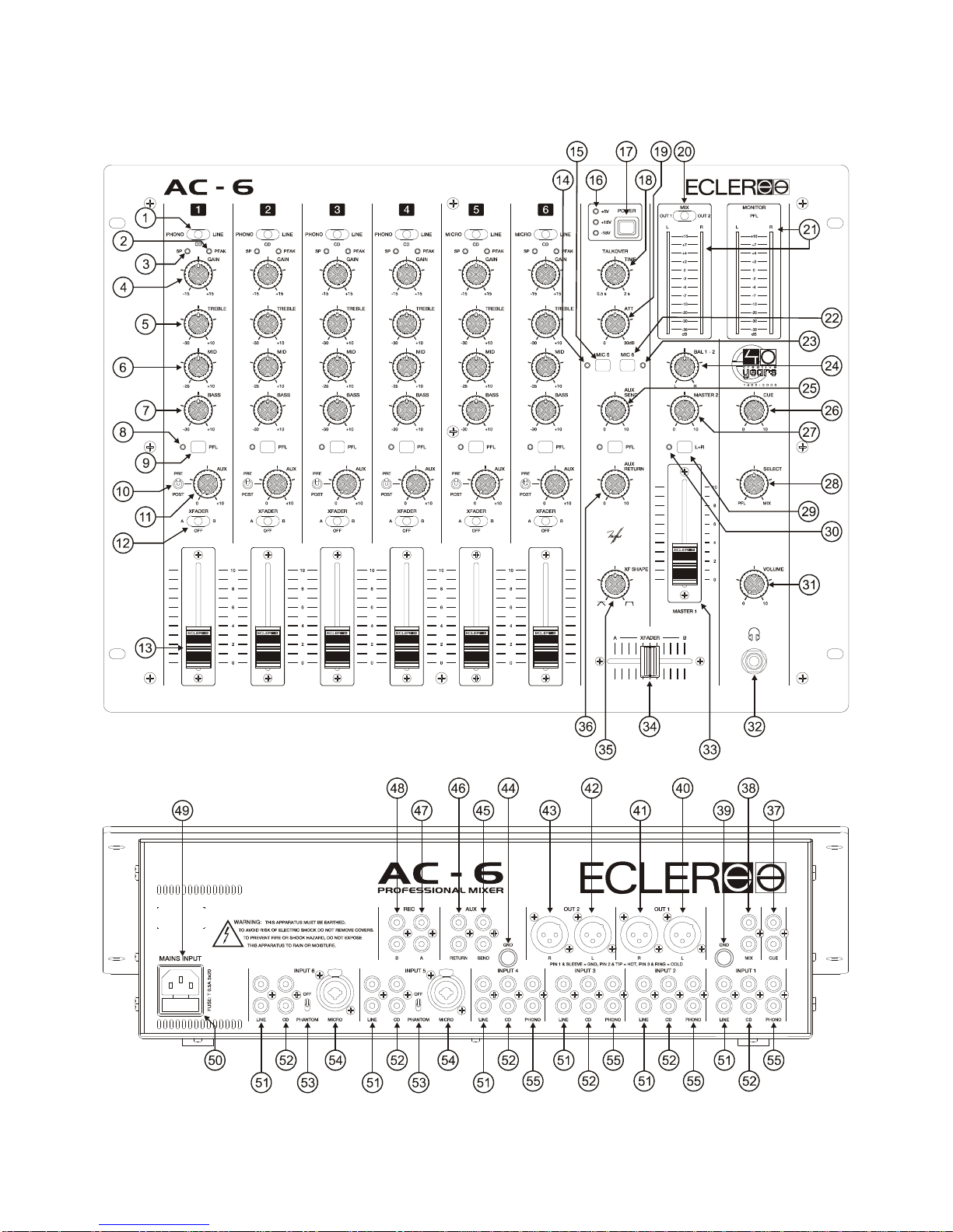
6. LISTA DE FUNCIONES
1. Selector de entradas
2. Indicador de pico de señal de entrada, PEAK
3. Indicador de presencia de señal en la entrada, SP
4. Ajuste de la sensibilidad de entrada, GAIN
5. Control de agudos, TREBLE
6. Control de medios, MID
7. Control de graves, BASS
8. Indicador luminoso, PFL
9. Conmutador de preescucha, PFL
10. Selector de envío auxiliar antes o después del fader, PRE / POST
11. Control de envío a auxiliar, AUX
12. Conmutador de envío a XFADER, XFA/MIX/XFB
13. Control de volumen de la vía
14. Indicador luminoso, MIC 5
15. Puesta en marcha del TALKOVER, MIC 5
16. Indicadores luminosos, +5/+18/-18V
17. Interruptor de puesta en marcha, POWER
18. Control tiempo de recuperación talkover, TIME
19. Control de efecto talkover, ATT
20. Selector de visualización del VU-metro, OUT1/MIX/OUT2
21. Vu-metro a leds
22. Puesta en marcha del TALKOVER, MIC 6
23. Indicador luminoso, MIC 6
24. Control de balance, BAL 1 -2
25. Control general de envio auxiliar, AUX SEND
26. Control volumen cue, CUE
27. Control de volumen OUT 2, MASTER 2
28. Monitorización del crossfade PFL/MIX, SELECT
29. Suma de señales izquierda y derecha, L+R
30. Indicador luminoso, L+R
31. Control de volumen auriculares, VOLUME
32. Jack estéreo auriculares
33. Control de volumen OUT 1, MASTER 1
34. Control de crossfader, XFADER
35. Ajuste de forma de crossfader, XF SHAPE
36. Control de retorno auxiliar, AUX RETURN
37. Salida cue, CUE
38. Entrada de mezcla, MIX
39. Borne de toma de masa, GND
40. Salida balanceada canal izquierdo, OUT 1 L
41. Salida balanceada canal derecho, OUT 1 R
42. Salida balanceada canal izquierdo, OUT 2 L
43. Salida balanceada canal derecho, OUT 2 R
44. Borne de toma de masa, GND
45. Salida para envío hacia auxiliar externo, AUX SEND
46. Entrada para retorno de auxiliar externo, AUX RETURN
47. Conector RCA de grabación, REC A
48. Conector RCA de grabación, REC B
49. Base de toma de red
50. Portafusibles
51. Entrada de línea, LINE
52. Entrada de CD, CD
53. Conmutador phantom, PHANTOM
54. Entrada balanceada de micrófono, MICRO
55. Entrada de phono, PHONO
19
7. DIAGRAMA DE FUNCIONES

20
NOTICE D’UTILISATION
1. NOTE IMPORTANTE 21
1.1. Précautions 21
2. INTRODUCTION 21
3. INSTALLATION 22
3.1. Emplacement et montage 22
3.2. Sources de signal 22
4. FONCTIONNEMENT ET UTILISATION 23
4.1. Mise en service 23
4.2. Pré-écoute 23
4.3. Gain et égalisation des voies 24
4.4. Envoi à des unités d'effets externes (AUX SEND) 24
4.5. Utilisation du XFADER 24
4.6. Talkover 24
4.7. Sorties 25
5. DIVERS 25
5.1. Boucles de masse, bruit de fond 25
5.2. Entretien 25
6. LISTE DE FONCTIONS 26
7. DIAGRAMME DE FONCTIONS 27
8. CARACTÉRISTIQUES TECHNIQUES 36
9. DIAGRAMME DE CONFIGURATION 37
10. DIAGRAMME DES BLOCS 38
Toutes les valeurs mentionnées dans ce document sont susceptibles d’être modifiées en raison des tolérances de
production. ECLER SA se réserve le droit de changer ou d’améliorer les processus de fabrication ou la présentation de
ses produits, occasionnant ainsi des modifications dans les spécifications techniques.
Table of contents
Languages:
Other Ecleree Music Mixer manuals


