Toa D-5.5E Instruction Manual

ToaElectricCo.,Ltd.
Model D-5.5, D-5.5E
ELECTRONIC MUSIC MIXER
Operating Instruction Manual
KOBE, JAPAN

Contents
GeneralDescription .........................................2
Features ..................................................3·4
FrontPanel: Names ofcomponents & theirusage (D-5.5) ....... 5~9
Rear Panel: Names of components & their usage (D-5.5) ..... 10~12
Front Panel: Names of components & their usage (D-5.5E) ...... 13
Rear Panel: Names of components & their usage (D-5.5E) ....... 14
Block and Level Diagrams
.................................15·16
Specifications (D-5.5, D-5.5E) ............................... 17
RackMountingInstructions .................................18
Procedure for changing internal switch setting ................ 19
CharacteristicsDiagam .....................................20
Appearance...............................................20
Precautions
1. Power Supply
The D-5.5 and the D-5.5E are designed to operate on local AC (50/60Hz) Mains,
±10%.
2. XLR Type Audio Connector
The connectors are wired as follows.
The pin 1 is ground (shield), the pin 2 cold (low, minus), the pin 3 hot (high,
plus).
3. Phantom Power Supply
The phantom power switch on each input channel permits the user to supply 48V
DC through the input connectors to a condenser microphone. If phantom power is
not required, the switch must be in the "off" position.
4. Description of components and function on the D-5.5, D-5.5E
Various descriptions are applied, depending on each manufacture. In our
Operating and Instruction Manual explanation of components and functions is
made according to our usage for them.
— 1 —

General Description
The TOA D-5.5 is a 19" rackmount or console configuration, eight-input stereo mixer especially designed
for electronic music and sound. It is expandable to a 32-input mixing system, with group, stereo and
mono outputs, and 16 MIDI-THRU jacks, when combined with two D-5.5E 12-input expansion units.
The D-5.5 was designed to perform many different applications in broadcast, live sound reinforcement,
and recording environments.
The D-5.5 provides four Group outputs, and mixing busses for Aux 1, Aux 2, Effects, Reverb, and Cue.
System features include: Sum output selectable pre- or post-fader (St. L + R); two Aux sends, selectable
pre-EQ/fader, post-EQ/pre-fader, or post-EQ/fader; Aux returns to Groups 1~4 and Stereo L, R, with pan,
level and crossfade controls; an effects patching loop and an internal spring reverb effect are returnable
to the 4 groups, stereo L, R, and Aux 1 & 2, with pan, level, and crossfade controls; dual bargraph meters,
selectable to Sum/Cue or Stereo L/R; a Headphone output with level control, a Cue buss output with
level control, and a Cue buss input.
Each input channel features a writing block to identify the source; tape/source selection switch; cue
switch; 60 mm fader; pad and trim controls; two-color LED to indicate signal prescence (green), or
clipping (red); channel on/off switch with orange LED indicator; 3-band EQ (high and low shelving-type,
and mid peaking-type with frequency sweep control); two Aux sends, selectable pre- or post-EQ; reverb
send to internal spring reverb; effects send; and four group sends via two pan and level controls.
Each of the four Groups features level and crossfade controls for returning Aux and Effects signals to the
Group mixing busses, and a stereo pan for assigning Group signals to the stereo Left and Right mixing
busses. The four groups and Stereo L, R also feature dual-color signal prescence/clip LED indicators; an
on/off switch with orange LED; writing block; 60 mm fader; and cue switch.
The D-5.5 rear panel features an RCA tape input, a 1/4" phone jack, and an electronically balanced XLR
(with switchable 48-volt phantom powering) for each input channel. Each input also has separate pre
and post accessory patch points and a direct output. Input channels 7 and 8 are front panel switchable to
stereo RIAA inputs, for use with magnetic cartridge turntable.
Group 1~4 output connections are RCA and 1/4" phone jacks; each features separate pre and post
accessory patch points (RCA). Stereo L, R and Sum output connections are individual RCA's, 1/4" phone
jacks, and electronically balanced XLR's with ground lift switches. Stereo L, R and Sum outputs also
feature pre and post accessory patching jacks.
The MIDI jacks are also located on the rear panel. "A" or "B" MIDI inputs are assignable to four
MIDI-THRU outputs (expandable to 16), allowing the use of multiple MIDI instruments without the data
loss or delay that may occur when several instruments are connected serially through their internal
MIDI-THRU jacks. Each MIDI-THRU output is provided with a front panel mounted on/off switch.
Also on the rear panel are a Buss-Link connector for connecting D-5.5 Expander units, separate 1/4"
phone jacks for stereo L, R Cue buss input and outputs, Aux 1, 2 sends and returns, external Reverb send
and return, and Effects send and return; a push button circuit breaker, chassis ground post, and six-foot
AC power cord complete the rear panel.
The D-5.5 combines with one D-5.5E for 20-inputs or two D-5.5E's for 32 input channels. Both units can
be mounted in a standard 19" rack, or may be used in a console configuration by removing the rack ears,
rotating the rear panel 90 degrees, and attaching the included wooden side panels. The mixers are
finished in an attractive and durable gray enamel, with 3-color control identification markings.
— 2 —

System Features:
Each Input Channel Feature:
8×4×2×1 configuration: 8 inputs; 4 sub groups;
stereo L & R; mono sum.
Expandable to 32 inputs with two 12 input D-5.5E
expansion unit.
Rear panel rotates 90 degrees to enable use as console
type mixer, or as 19" rack mount mixer with the
included mounting brackets; removable wooden side
panels.
Selectable 2×4 MIDI Thru function; expandable to
2×16.
Stereo RIAA Inputs for turntables with magnetic
cartridge; selectable from front panel; input channels
7 & 8.
2 Aux returns to four groups and Stereo L & R, with
level and crossfade controls.
Internal spring reverb with dedicated 2-band EQ. Can
return to four groups, stereo L & R, and Aux 1, 2 with
pan, level, and crossfade controls.
Effects patching loop, returnable to four groups,
stereo L & R, and Aux 1, 2 with pan, level, and
crossfade controls.
Dual bargraph meters; selectable between Sum/Cue
and St L & R.
Sum Output (St L & R); selectable pre or post fader.
2 Aux sends; selectable "pre-EQ and fader," "post-
EQ, pre-fader," "post-EQ and fader."
Mono reverb send and mono effects send; both are
"post EQ and fader."
Headphones output with level control.
Push button circuit breaker instead of fuse.
Tape/Source Selection switch.
2-color LED indicator for signal presence (green) and
clip (red).
Pad and trim controls.
3-band EQ; shelving type for high and low; peaking
mid with sweep control.
2 Aux sends; selectable pre or post.
Reverb send to internal spring reverb; post EQ and
fader.
Effect send; post EQ and fader.
4 group sends via 2 level and pan controls.
Channel on/off switch with LED indicator (orange).
Writing block.
60 mm fader.
Cue switch.
The D-5.5 is an 8 input, 19" rack mountable mixing console, featuring superior
audio performance, system expandability, and unique "user friendly" design.
Each Group Features:
Level and crossfade controls for returning aux and
effects signals to group busses.
Stereo pan pot to Stereo L & R busses.
2-color LED indicator for signal presence (green) and
clip (red).
Channel on/off switch with LED indicator (orange).
Writing block.
60 mm fader.
Cue switch.
Features
— 3 —

Features
Stereo L & R Features:
Sum Connections:
2-color LED indicator for signal presence
(green) and clip (red).
Channel on/off switch with LED indicator
(orange).
Writing block.
60 mm fader.
Cue switch.
REAR PANEL:
Other Connections:
L & R Cue input: 1/4" phone jacks.
L & R Cue Buss output: 1/4" phone jacks.
Aux 1 & 2 sends and Aux 1 & 2 returns: 1/4" phone
jacks.
Rev send, and return: 1/4" phone jacks.
Effects send, and return: 1/4" phone jacks.
A and B MIDI Input: DIN plug.
1-4 MIDI Thru: DIN plug.
Buss Link: Multi-pin computer-type connector.
Input Channel Connections:
Separate pre and post accessory patch points: RCA.
Direct Output: RCA.
Source inputs: 1/4" phone jack, and electronically
balanced XLR with individually switchable 48-volt
phantom power.
Tape input: RCA.
RIAA inputs on channels 7 & 8: RCA.
Group 1-4 Connections:
Separate pre and post accessory patch points:
RCA.
Direct Output: RCA, 1/4" phone jack.
Stereo L & R Connections:
Separate pre and post accessory patch points: RCA.
Direct Output: RCA. 1/4" phone jack, and electroni-
cally balanced XLR with ground lift switch.
— 4 —
Direct Output: RCA, 1/4" phone jack, and electroni-
cally balanced XLR with ground lift switch.

Front Panel (D-5.5)
INPUT CHANNEL
(D-5.5)
Phono EQ (RIAA) IN/OUT Switch (RIAA IN/OUT)
This switch is available for input channels 7 and 8 only and is active when a
turntable with magnetic type cartrige is connected to the Phono input channel.
The switch is a "push-in push-out" type. The "out" position provides a flat
frequency response.
Tape/Source Switch (TAPE/SOURCE)
This switch is provided for selecting the desired input signals. When monitoring
the signals from the XLR connector, phone jack and phono inputs, the switch
should be set to the "SOURCE" position. When the signal from the "Tape In"
input is desired, the switch should be set to the "TAPE" position.
Signal/Peak LED Indicator (SIG/PEAK)
The dual color LED indicator lights green when the pre or post EQ signal level
reaches more than -30dB, and turns red when the signal level reaches 3dB
below clipping, giving a visual reference for optimum setting of the trim control.
Input Level Selector (PAD)
The selector provides 30dB attenuation of the sensitivity of the XLR connector,
phone jack and phono inputs at the "30" position. The "0" position shows the
sensitivity indicated on the panel. The correct setting should be made according
to the output level of the equipment connected.
Input Trim Control (TRIM)
The trim control adjusts the gain of the preamp stage of the associated channel,
providing 30dB of gain control. When the trim control is set to the "0" position
with the input level selector at the "0" position, the nominal levels of the
associated inputs are as follows.
a. Mic input: -60dB
b. Tape input: -20dB
c. Phono input: -50dB (Input channels, 7 and 8 only)
The trim control and input level selector of each channel should be properly
adjusted so that the peak LED just begins to turn red from green or only flash red
occasionally. This will ensure lowest distortion level and optimum signal to
noise ratio.
High Equalizer Control (HIGH)
The high EQ control alters the high frequency response of the input channel,
providing ±10dB at 4kHz, and ±15dB at 20kHz of continuously variable active
shelving equalization. The "0" detented position provides flat audio response.
Mid Equalizer Center Frequency Control (MID FREQ)
This control alters the center frequency of the mid EQ control in the range from
200Hz to 5kHz.
Mid Equalizer Control (MID LEVEL)
This control alters the mid frequency response of the input channel, providing
±15dB at the center frequency of peaking equalization. The "0" detented
position provides flat audio response.
Low Equalizer Control (LOW)
The low EQ control provides ±10dB at 150Hz and ±15dB at 20Hz of
continuously variable active shelving equalization. The "0" detented position
provides flat audio response.
AUX 1 Control (AUX 1)
This control determines the level of the input signal to be fed to the aux 1 buss.
When in the center detent position the control is off, and no signal is assigned.
Rotating the control counter-clockwise increases the amount of pre-fader/post-
EQ signal assigned to the buss. Rotating the control clockwise increases the
amount of post-fader/post -EQ signal.
Note: "Pre-fader/post-EQ" can be changed to the pre-EQ signal with an internal
switch. (See page 19 for details.)
— 5 —

The D-5.5 incorporates two, switchable MIDI inputs
and four MIDI THRU outputs. With the D-5.5E, six
additional MIDI THRU outputs are available.
MIDI LED Indicator (MIDI IN)
This yellow LED indicates the presence of MIDI data
at the MIDI input jack on the rear panel (MIDI IN).
MIDI Input Selector Switch (MIDI IN, A, B)
This switch selects either the MIDI input B signal in
the "push" position, or A signal in the "release"
position.
CAUTION
While the MIDI LED indicator is flashing, do not
operate either the MIDI input selector switch or
the MIDI THRU on/off switch in order to avoid
malfunction of connected MIDI equipment.
MIDI THRU ON/OFF Switch (MIDI THRU ON/OFF)
This switch is for "on" or "off" function of each MIDI
THRU output. The MIDI THRU is "on" in the "push"
position.
(D-5.5E)
MIDI THRU
(D-5.5)
Group Assign Pan Control 1 and 2 (GROUP PAN)
This pan control assigns the amount of signal
determined by the group assign control to the group
1 and 2 busses, providing equal output to the group 1
and 2 busses at the center position. Rotating the pan
control clockwise decreases the amount of signal to
be fed to the group 2 buss, keeping the original level
of the signal for the group 1 buss, while rotating the
control counter-clockwise decreases the amount of
signal to be fed to the group 1 buss, keeping the
original level of the signal for the group 2 buss.
Cue Switch (CUE)
The cue switch is for monitoring the post-EQ,
pre-fader signal in each input channel through
headphone and cue output. The switch is a "push-on
push-off" type. When more than two switches are
"on" the signals are combined.
Group Assign Control 3 and 4 (GROUP LEVEL)
This control determines the amount of a given input
signal assigned to the group 3 and 4 via the group
assign control.
Group Assign Pan control 3 and 4 (GROUP PAN)
This pan control assigns the amount of signal
determined by the group assign control to the group
3 and 4 busses, providing equal output to the group 3
and 4 busses at the detent center position. Rotating
the pan control counter-clockwise decreases the
amount of the signal to be fed to the group 4 buss,
keeping the original level of the signal for the group 3
buss, while rotating the pan control clockwise
decreases the amount of the signal to be fed to the
group 3 buss, keeping the original level of the signal
for the group 4 buss.
Channel Switch ON Indicator (CHANNEL ON)
The LED indicator lights orange when the channel
on/off switch is "on".
Channel ON/OFF Switch (CHANNEL)
This pushbutton connects or disconnects the input
signal to the mixing busses.
Writing Block
The name of the input equipment or microphone
setting can be written in with an erasable felt pen or
grease pencil.
Input Fader
The fader provides continuously variable adjustment
of the channel's output to the mixing busses. The
nominal level is at the "0" position, with the fader
retaining a l0dB margin.
AUX 2 Control (AUX 2)
This control determines the level of the input signal
to be fed to the aux 2 buss. When in the center detent
position the control is off, and no signal is assigned.
Rotating the control counter-clockwise increases the
amount of pre-fader/post-EQ signal assigned to the
buss.
Rotating the control clockwise increases the amount
of post-fader/post-EQ signal.
Note: "Pre-fader/post-EQ" can be changed to pre-EQ
signal with an internal switch. (See page 19 for
details.)
Reverb Control (REV)
This control determines the amount of post-fader/
post-EQ signal assigned to the reverb buss from a
given input channel, and thus the level of reberb for
that channel.
Effects Control (EFF)
This control determines the amount of post-fader/
post-EQ signal assigned to the effect buss from a
given input channel, and thus the level of effects for
that channel.
Group Assign Control 1 and 2 (GROUP LEVEL)
This control determines the level of input signal
assigned to the group buss 1 and 2 via the group
assign pan control.
Front Panel (D-5.5, D-5.5E)
— 6 —

Front Panel (D-5.5)
OUTPUT CHANNEL
Level Control for Return to Group (RET TO GROUP,
LEVEL)
This control adjusts the level of signal from the AUX
1 return and AUX 2 return, or the EFF return and
REV return.
Cross-fate Control to Group (RET TO GROUP,
X-FADE)
With the return signal select switch set to the
REV/EFF position, the EFF and REV return signal
levels are equally assigned to the group buss. When
the control is in its center, detent position. Rotating
the control counter-clockwise decreases the signal
level of the EFF return, keeping the original level of
the REV return signal, while rotating the control
clockwise decreases the signal level of the REV
return, keeping the original level of the EFF return
signal.
With the return signal select switch set to the aux
1/aux 2 position, the aux 1 and aux 2 return signal
levels are equally assigned to the group buss when
the control is in its center, detent position. Rotating
the control counter-clockwise decreases the signal
level of the aux 2 return signal, keeping the original
level of the aux 1 return signal, while rotating the
control clockwise decreases the signal level of the
aux 1 return, keeping the original level of the aux 2
return signal.
Return Signal Select Switch (REV/EFF, AUX 1 /
AUX 2)
This switch selects either the REV/EFF return signals
or the AUX 1 / AUX 2 return signals to feed them to
the group buss.
Pan Pot
(PAN)
The pan pot control assigns the fader output signal of
each group channel to the stereo L and R mixing
busses. At the detented center position, the pan pot
routes the signal equally to the L and R mixing
busses. Panning from one side to the other gradually
assigns the input signal to either the stereo L or R
mixing busses exclusively.
Signal/Peak LED Indicator (SIG/PEAK)
The LED indicator lights in green colour when the
group output signal reaches more than -30dB, and
turns to red when the groups signal reaches -3dB
below clipping, giving a visual reference for adjust-
ment of the group fader. (See NOTE 1)
Group Channel ON indicator (CHANNEL ON)
The LED indicator lights orange when the group
channel ON/OFF switch is "on".
Group Channel ON/OFF Switch (CHANNEL)
This pushbutton connects or disconnects the signal
to the group output and stereo L/R busses.
— 7 —
NOTE 1:
Levels
should be
adjusted
so that the LED only
indicates that the channel is being over driven
and the level should be reduced.
flashes red intermittently. A steady red light

Front Panel (D-5.5)
Writing Block
The name of the source signal can be written in with
an erasable felt pen or grease pencil.
Group Fader (GROUP 1 - 4)
The 60mm fader provides continuously variable
adjustment of the group level to the stereo L and R
busses, and the group output connectors.
Cue Switch (CUE)
The cue switch is for monitoring the pre-fader signal
in each group channel through the headphones and
cue out. This function is for independent audition of
the group mixes.
Level Control for Aux 1 Return to Stereo L and R
(AUX/RET, LEVEL)
This control adjusts the signal level from the AUX 1
return and feeds it to the stereo L and R busses via
the pan control.
Pan Pot
(PAN)
The pan control assigns the signal from the AUX 1
return to the stereo L and R busses.
Cue Switch (CUE)
The switch permits monitoring the AUX 1 signal
prior to the AUX 1 return level control.
Level Control for Aux 2 Return to Stereo L and R
(AUX 2 RET, LEVEL)
This control adjusts the signal level from the AUX 2
return and feeds it to the stereo L and R busses via
pan control.
Pan Pot
(PAN)
The pan control assigns the signal from the AUX 2
return to the stereo L and R busses.
Cue Switch (CUE)
The switch permits monitoring the AUX 2 signal
prior to the AUX 2 return level control.
Level Control for Reverb Return or Built-in Reverb
to Stereo L and R (REVERB RET, LEVEL)
The control adjusts the signal level from the reverb
or the built-in reverb and feeds it to the stereo L and
R busses via the pan control.
Pan Pot
(PAN)
The pan control assigns the signal from the reverb
return to the stereo L and R busses.
Cue Switch (CUE)
The switch permits monitoring the signal prior to the
reverb return level control.
Level Control for Effect Return to Stereo L and R
(EFF RET, LEVEL)
This control adjusts the signal level from the effects
return and feeds it to the stereo L and R busses via
the pan control.
Pan Control (PAN)
The pan control assigns the signal from the effects
return to the stereo L and R busses.
Cue Switch (CUE)
The switch permits monitoring the signal prior to the
effect return level control.
Sum Select Switch (SUM SLECT, PRE/POST)
This switch selects either the channel pre-fader or
post-fader signals derived from the stereo L and R
busses, and sends them to the SUM output. The
switch provides pre-fader signal in the "push"
position, and post-fader signal in the "release"
position.
Signal/Peak LED Indicator (SIG/PEAK)
The LED indicator lights green when the sum output
signal reaches more than -30dB, and turns to red
when the signal level reaches -3dB below clipping,
giving a visual reference for adjustment of the SUM
channel fader. (See NOTE 1)
Sum Channel ON Indicator and Channel ON/OFF
Switch (CHANNEL ON)
The LED indicator lights orange when the channel
on/off switch is "on".
Writing Block
Sum Out Fader (SUM)
The fader provides continuously variable adjust-
ment of the SUM output.
Cue Switch (CUE)
The cue switch permits monitoring the pre Sum-
fader signal through the headphone and cue output.
Aux 1 / 2 Send Control (AUX SEND, AUX 1 / AUX 2)
The aux 1 and aux 2 send controls govern the overall
level of signal sent to on-stage monitor amplifiers, or
an outboard effect device thought the aux 1 and 2
send jacks on the rear panel.
Reverb Send Control (REV/EFF SEND, REV)
This control governs the overall level of signal sent
to the built-in reverb unit or an outboard effect
device through the reverb send jack on the rear
panel.
Effect Send Control (REV/EFF SEND, EFF)
This control governs the overall level of signal sent
to an outboard effects device through the Effect Send
jack on the rear panel.
Internal Reverb Equalizer Control (INT REV EQ,
HIGH/LOW)
These controls alter the frequency response of the
built-in reverb circuitry. The high EQ control pro-
vides ±10dB at 4kHz, and ±15dB at 20kHz of
continuously variable active shelving equalization.
The low EQ control provides ±10dB at 150Hz and
±15dB at 20Hz of continuously variable active
shelving equalization. The "0" detented position of
both controls provide flat audio response.
— 8 —

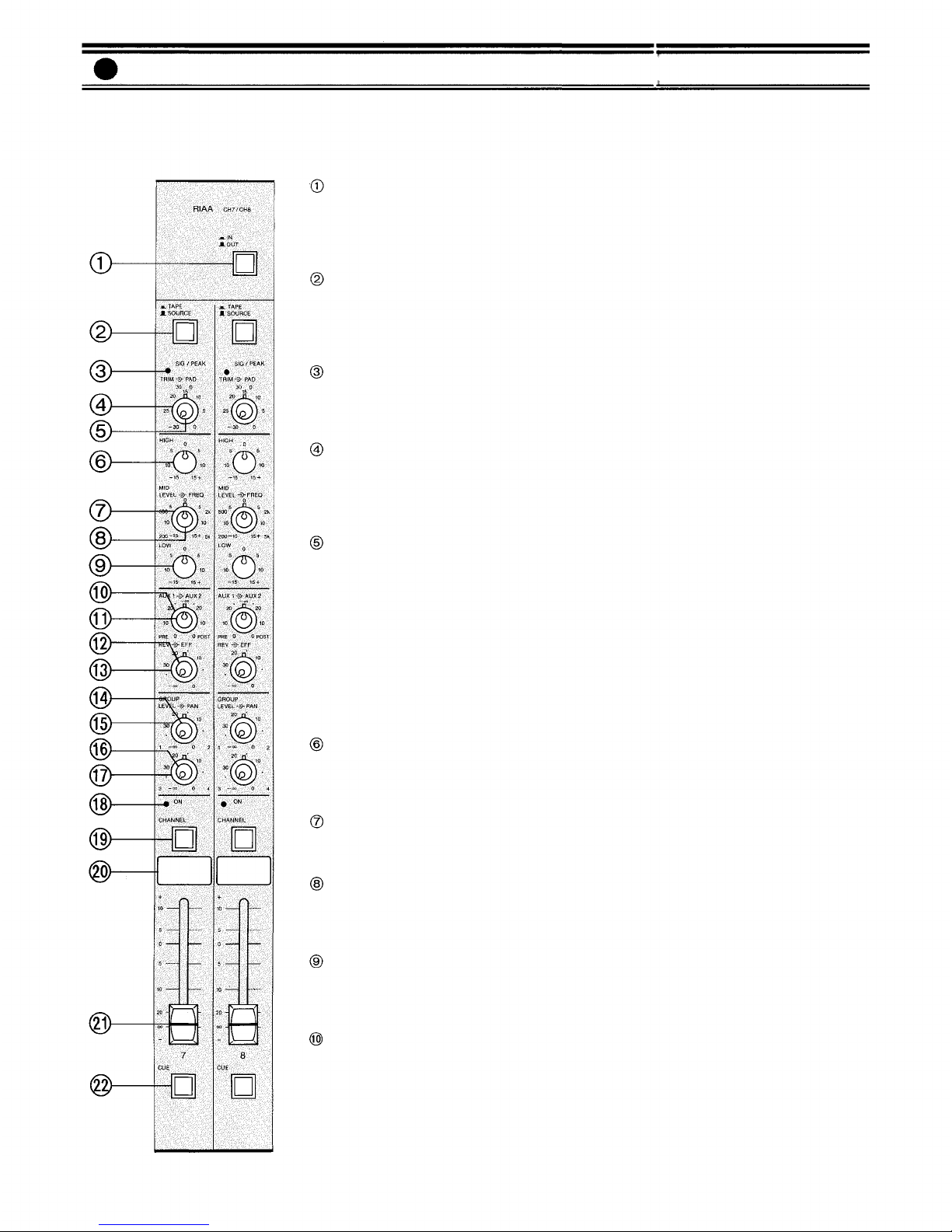
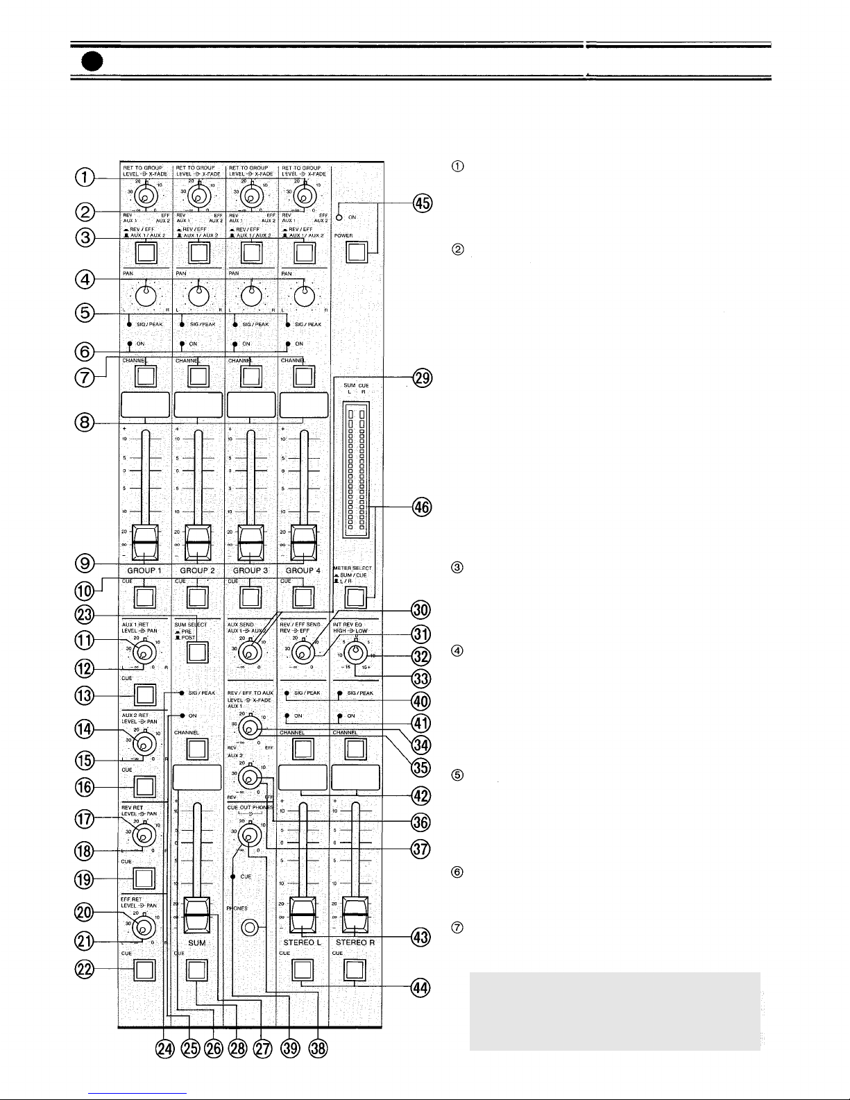
Level Control for Effect and Reverb Return to Aux 1
(REV/EFF TO AUX, LEVEL AUX 1)
This control governs the amount of reverb signal
(built-in or outboard) returned through the reverb
return jack (REV RET), and effect signal returned
through the effect return jack (EFF RET) to AUX 1
mixing buss. The signals of REV RET and EFF RET
are controlled simultaneously.
Cross-fade Control to Aux 1 (REV/EFF TO AUX,
X-FADE)
When this control is in the center position, the REV
RET and EFF RET signals are equally assigned to the
AUX 1 mixing buss. Rotating the control counter-
clockwise decreases the EFF RET signal level,
keeping the original level of the REV RET signal.
Rotating the control clockwise decreases the REV
RET signal level, keeping the original level of the
EFF RET signal.
Level Control for Effect and Reverb Return to Aux 2
(REV/EFF TO AUX, LEVEL AUX 2)
This control governs the amount of reverb signal
(built-in or outboard) returned through the reverb
return jack (REV RET), and effect signal returned
through the effect return jack (EFF RET) to AUX 2
mixing buss. The signal ofREV RET and EFF RET are
controlled simultaneously.
Cross-Fade Control to Aux 2 (REV/EFF TO AUX,
X-FADE)
When the control is in the center position, the REV
RET and EFF RET signals are equally assigned to the
AUX 2 mixing buss. Rotating the control counter-
clockwise decreases the signal level of the EFF RET,
keeping the original level of the REV RET signal.
Rotating the control clockwise decreases the signal
level of the REV RET, keeping the original level of
the EFF RET signal.
Cue Out Level Control and Cue ON LED Indicator
(CUE
OUT,
CUE)
The cue out level control adjusts both the stereo L
and R signals and the Cue in (L, R) signal fed to the
Cue output on the rear panel (CUE OUT) and permits
stereo monitoring when the cue switch is "off".
When the cue switch is "on", the control adjusts the
corresponding cue signal. When two or more of the
cue switches are "on", the control adjusts the
corresponding combined cue signals. The cue on
LED lights when one of the cue switches is "on".
Headphone Level Control and Jack (PHONES)
The phones level control adjusts both the stereo L
and R signals and the Cue IN (L, R) signal fed to the
phones output and permits stereo monitoring when
the cue switch is "off". When the cue switch is "on",
the control adjusts the corresponding cue signal.
When two or more of the cue switches are "on", the
control adjusts the corresponding combined cue
signals. The headphone jack will accept any stereo
headphone with 8 ohms impedance, or higher.
Signal/Peak LED Indicator (SIG/PEAK)
The LED indicator lights green when the stereo out L
or R signals reach more than -30dB, and turns to red
when the stereo out L or R signals reach -3dB below
clipping, giving a visual reference of adjustment of
the stereo L or R faders. (See NOTE 1)
Stereo Channel ON Indicator and Channel ON/OFF
Switch (CHANNEL ON)
The LED indicator lights orange when the channel
switch is "on".
Writing Block
Stereo Left and Right Fader (STEREO L, R)
The fader provides continuously variable adjust-
ment of the stereo L or R output, and the signal level
to the Sum out channel when the sum select switch
is set in the "POST" position.
Cue Switch (CUE)
The cue switch permits monitoring the pre stereo L,
R fader signals through the headphones and cue out.
Power LED indicator and Switch (POWER)
The power switch alternately turns AC power to the
D-5.5 "on" and "off". The LED indicator lights when
the switch is "on".
Dual LED Bargraph Meter and Meter Select Switch
(METER SELECT, SUM/CUE, L/R)
The meter indicates the sum output (left side) and
cue output (right side) when the meter select switch
is set in the "push" position, and indicates the stereo
L output (left side) and stereo R output (right side)
when the meter select switch is set in the "release"
position.
— 9 —

RCA Stereo L & R Post
Accessory Patch Points
(POST IN/OUT)
These RCA pin jacks are unba-
lanced, with a nominal level of —
10dB. Input jack impedance is
10k ohms, and output jack impe-
dance is 1k ohms. The Accessory
jacks allow signal processing and
effect devices to be inserted into
the signal path. The regular sig-
nal path is interrupted when a
plug is inserted into the Acces-
sory In jack.
RCA Group Pre Accessory
Patch Points (PRE IN/OUT)
These RCA pin jacks are unba-
lanced, with a nominal level of
-10dB. Input jack impedance is
10k ohms, and output jack impe-
dance is 1k ohms. The Accessory
jacks allow signal processing and
effect devices to be inserted into
the signal path. The regular sig-
nal path is interrupted when a
plug is inserted into the Acces-
sory in jack.
RCA Group Post Accessory
Patch Points (POST IN/OUT)
These RCA pin jacks are unba-
lanced, with a nominal level of
—10dB. Input jack impedance is
10k ohms, and output jack impe-
dance is 1k ohms. The Accessory
jacks allow signal processing and
effect devices to be inserted into
the signal path. The regular sig-
nal path is interrupted when a
plug is inserted into the Acces-
sory in jack.
AC Power Cord
The power cord is of the three-
wire type with proper grounding
facilities built-in. (6ft.)
Earth Terminal
This terminal can be used to
ground other devices to the D-5.5
to reduce hum and shock hazard.
Aux 2 Send Jack (AUX 2 SEND)
This 1/4" phone jack can be used
either as a monitor send, or in
conjunction with the Aux 2 Re-
turn jack to connect an outboard
effects device (ie., delay or re-
verb) to the D-5.5. The Aux 2
Send jack should be connected to
the input of the effect. Nominal
output level is +4dB with an
impedance of 1k ohms.
Pushbutton Circuit Breaker (1A)
(PUSH RESET)
This breaker is designed to pro-
tect the D-5.5 in the event of
internal or external fault. Wait
about two minutes after correct-
ing the fault and push the button
to reset the system and restore
proper operation.
L & R Cue Buss Output
(CUE
OUT
L/R)
These 1/4" phone jacks provide
the same signal as the headphone
output, and are used for monitor-
ing the signals of the cue buss or
stereo L and R busses through
monitor speakers.
This jack has a nominal output
level of +4dB and an impedance
of 1k ohms.
Aux 1 Send Jack (AUX 1 SEND)
This 1/4" phone jack can be used
either as a monitor send, or in
conjunction with the Aux 1 Re-
turn jack to connect an outboard
effects device (ie., delay or re-
verb) to the D-5.5. The Aux 1
Send jack should be connected to
the input of the effect. Nominal
output level is +4dB with an
impedance of 1k ohms.
Sum Output jacks
(SUM OUTPUT)
The unbalanced RCA pin jack,
1/4" phone jack and electronical-
ly balanced XLR connector are
wired in parallel. The RCA jack
has a nominal output level of
-l0dB and an impedance of 1k
ohms, and the 1/4" phone jack
has a nominal output level of
+4dB and an impedance of 1k
ohms. The XLR connector has a
nominal output level of +4dB
and an impedance of 1k ohms.
All jacks may be used simul-
taneously.
Ground Lift Switch (GND)
These switch are assigned to the
XLR Sum Output and Stereo L &
R connectors, and are used to
avoid ground loops and induced
hum that sometimes occur when
connecting the D-5.5's XLR Sum
Output or Stereo L & R Output
with other equipment. Sliding
the Ground Lift Switch from the
NORMAL position to the LIFT
position breaks the ground con-
nection and may reduce hum and
noise. For most applications the
witch should be left in the NOR-
MAL position.
Effect Return Jack (EFF RET)
This 1/4" phone jack is used in
conjunction with the Effect Send
jack to connect an outboard
effects device (ie., delay or re-
verb) to the D-5.5. The Effect
Return jack should be connected
to the output of the effect.
Nominal input level is — 20d B
with an impedance of 10k ohms.
Reverb Return Jack (REV RET)
This 1/4" phone jack is used in
conjunction with the Reverb
send jack to connect an outboard
effects device (ie., delay or re-
verb) to the D-5.5. The Effect
Return jack should be connected
to the output of the effect device.
Nominal input level is -20dB
with an impedance of 10k ohms.
When a plug is inserted into this
jack, the built-in reverb circuitry
is automatically cut off.
CAUTION - The ground pin on
the AC plug should not be re-
moved under any circumstances.
If the D-5.5 must be used on an
AC circuit with no ground or and
open ground, then a suitable
grounding adapter should be
used and its ground terminal
should be securely attached to a
good earth connection. Failure to
do so will result in increased
noise and shock hazard.
Aux 1 Return Jack (AUX 1 RET)
This 1/4" phone jack can be used
in conjunction with the Aux 1
Send jack to connect an outboard
effects device (ie., delay or re-
verb) to the D-5.5. The Aux 1
Return jack should be connected
to the output of the effect.
Nominal input level is — 20dB
with an impedance of 10k ohms.
Aux 2 Return Jack (AUX 2 RET)
This 1/4" phone jack can be used
in conjunction with the Aux 2
Send jack to connect an outboard
effects device (ie., delay or re-
verb) to the D-5.5. The Aux 2
Return jack should be connected
to the output of the effect.
Nominal input level is -20dB
with an impedance of 10k ohms.
Effect Send Jack (EFF SEND)
This 1/4" phone jack is used in
conjunction with the Effect Re-
turn jack to connect an outboard
effects device (ie., delay or re-
verb) to the D-5.5. The Effect
Send jack should be connected to
the input of the effect. Nominal
output level is +4dB with an
impedance of Ik ohms.
Reverb Send Jack (REV SEND)
This 1/4" phone jack is used in
conjunction with the Reverb Re-
turn jack to connect an outboard
effects device (ie., delay or re-
verb) to the D-5.5. The Reverb
Send jack should be connected to
the input of the effect. Nominal
output level is +4dB with an
impedance of 1k ohms.
Rear Panel (D-5.5)
RCA Sum Post Accessory
Patch Points
(POST IN/OUT)
These RCA pin jacks are unba-
lanced, with a nominal level of
—l0dB. Input jack impedance is
10k ohms, and output jack impe-
dance is 1k ohms. The Accessory
jacks allow signal processing and
effect devices to be inserted into
the signal path, the regular signal
path is interrupted when a plug
is inserted into the Accessory in
jack.
RCA Sum Pre Accessory
Patch Point
(PRE IN/OUT)
These RCA pin jacks are unba-
lanced, with a nominal level of
—l0dB. Input jack impedance is
10k ohms, and output jack impe-
dance is 1k ohms. The Accessory
jacks allow signal processing and
effect devices to be inserted into
the signal path. The regular sig-
nal path is interrupted when a
plug is inserted into the Acces-
sory in jack.
Stereo L & R output jacks
(ST L & ST R OUTPUT)
The unbalanced RCA pin jacks,
1/4" phone jacks and electroni-
cally balanced XLR connectors
are wired in parallel. The RCA
jack has a nominal output level of
—l0dB and an impedance of 1k
ohms, and the 1/4" phone jack
has a nominal output level of
+4dB and an impedance of 1k
ohms. The XLR connectors have
a nominal output level of +4dB
and an impedance of 1k ohms.
All jacks may be used simul-
taneously.
RCA Stereo L & R Pre
Accessory Patch Points
(PRE IN/OUT)
These RCA pin jacks are unba-
lanced, with a nominal level of
—l0dB. Input jack impedance is
10k ohms, and output jack impe-
dance is 1k ohms. The Accessory
jacks allow signal processing and
effect devices to be inserted into
the signal path. The regular sig-
nal path is interrupted when a
plug is inserted into the Acces-
sory in jack.
Rear Panel (D-5.5)
Group Output jacks
(GROUP OUTPUT)
The unbalanced RCA pin jacks
and 1/4" phone jacks are wired in
parallel. The RCA jack has a
nominal output level of — 10dB
and an impedance of 1k ohms,
while the 1/4" jack has a nominal
output level of +4dB and an
impedance of 1k ohms. The jacks
may be used simultaneously.
RCA Tape Input (TAPE IN)
These RCA pin jacks are unba-
lanced, with a nominal level of
-20dB and impedance of 10k
ohms, and accept input sources
from -20dB to + 10dB. Proper
adjustment of both trim control
(TRIM) and input fader ensure
optimum signal-to-noise ratio
and minimum distortion.
Direct Output (DIRECT OUT)
The Direct Output on each chan-
nel utilizes an unbalanced RCA
pin jack with an impedance of 1k
ohms and a level of -10dB. The
Direct Output is post-EQ/post-
fader, and is useful for recording
and for sending individual in-
struments to a main PA mixer
through direct boxes.
RCA Post Accessory Patch
Points (POST IN/OUT)
These RCA pin jacks are unba-
lanced, with a nominal level of
-10dB. Input jack impedance is
10k ohms, ana! output jack impe-
dance is 1k ohms. The Accessory
jacks allow signal processing and
effect devices to be inserted into
the signal path. The regular sig-
nal path is interrupted when a
plug is inserted into the Acces-
sory In jack.
RCA Pre Accessory Patch
Points (PRE IN/OUT)
These RCA pin jacks are unba-
lanced, with a nominal level of
-10dB. Input jack impedance is
10k ohms, and output jack impe-
dance is 1k ohms. The Accessory
jacks allow signal processing and
effect devices to be inserted into
the signal path. The regular sig-
nal path is interrupted when a
plug is inserted into the Acces-
sory in jack.
1/4" phone Channel Input (IN-
PUT)
This jack is a standard 1/4" phone
jack, with a nominal level of
-40dB and an impedance of
100k ohms, and accepts input
sources from -40dB to +20dB.
Proper adjustment ofthe pad and
tirm control (PAD/TRIM) and in-
put fader ensure optimum signal-
to-noise ratio and minimum dis-
tortion. When a plug is inserted
into the 1/4" input jack, the cor-
responding XLR mic input or
phono input is automatically
switched out of the input circuit-
ry-
Phantom Power Switches
(PHANTOM1~8)
The phantom power switch on
each input channel permits the
user to supply 48V DC through
the input connectors to a conde-
nser microphone. If phantom
power is not required, the switch
must be in the "off" position.
Earth Terminal
These may be used to provide
ground connection for tape decks
or turntables.
MIDI Thru Connectors
(MIDI THRU)
The MIDI signal from the MIDI
Inputconnector (MIDI I N, A/B) is
split and sent unaltered to the
four MIDI Thru connectors on the
D-5.5, and to six more MIDI Thru
connectors on the D-5.5E, if used.
Each of the MIDI Thru jacks can
be connected to a different synth-
esizer's MIDI Input jack, allow-
ing one MIDI keyboard or se-
quencer to control up to four
other MIDI synths. (ten when
using the D-5.5E and sixteen
when using the two D-5.5E's.)
Balanced XLR Microphone In-
put
(MIC)
The XLR-type microphone input
connectors are electronically ba-
lanced with a nominal level of
—60dB and an input impedance
of 1k ohms, and will accept sig-
nals from -60dB to 0dB. Phan-
tom powering is provided for use
with condenser-type mic-
rophones (see PHANTOM), and
once again the proper adjustment
of Pad and Trim control (PAD/
RTIM) and Input Fader will in-
sure optimum signal-to-noise
ratio and minimum distortion.
The mic input is automatically
disconnected when either the
corresponding the 1/4" phone
jack is used.
MIDI Input DIN Connectors
(MIDI IN, A/B)
These connectors will accept the
MIDI output of any synthesizer,
sequencer, or other MIDI device.
Use of non-MIDI-standard DIN
cables, or of cables longer than
5m (16'5") may result in improp-
er operation and data loss.
RCA Phono (RIAA)
Inputs (PHONO)
These RCA pin jacks have a
nominal level of — 50dB and an
impedance of 50k ohms, and
accept input sources from -50dB
to +10dB. Proper adjustment of
the pad and trim control (PAD/
TRIM) and input fader ensure
optimum signal-to-noise ratio
and minimum distortion. When
using a turntable with magnetic
cartridge, place the phono EQ
IN/OUT switch on the front panel
to the "in" position.
Buss Link Connector (BUSS
LINK)
This connector is used to link the
D-5.5 with the D-5.5E. Expander.
A six-foot connecting cord is
included with the D-5.5E.
L & R Cue Input (CUE IN L/R)
These 1/4" phone jacks allow
access to the stereo cue buss.
This feature is especially conve-
nient during recording applica-
tions. These jacks have a nominal
input level of -10dB with an
impedance of 10k ohms.
— 11 —— 10 — — 12 —

Front Panel (D-5.5E)
* The names of the functions on the D-5.5E are specified below as function of the input channel on the D-5.5 is
the same as the D-5.5E. Difference in functions are explained.
Power LED indicator and Switch (POWER)
The power switch alternately turns AC power to the D-5.5E "on" and "off".
The LED indicator lights when the switch is "on".
Tape/Source Switch (TAPE/SOURCE)
Signal/Peak LED Indicator (SIG/PEAK)
Input Level Selector (PAD)
Input Trim Control (TRIM)
High Equalizer Control (HIGH)
Mid Equalizer Center Frequency Control (MID FREQ)
Mid Equalizer Control (MID LEVEL)
Low Equalizer Control (LOW)
AUX 1 Control (AUX 1)
AUX 2 Control (AUX 2)
Reverb Control (REV)
Effects Control (EFF)
Group Assign Control 1 and 2 (GROUP LEVEL)
Group Assign Pan Control 1 and 2 (GROUP PAN)
Group Assign Control 3 and 4 (GROUP LEVEL)
Group Assign Pan Control 3 and 4 (GROUP PAN)
Channel Switch ON Indicator (CHANNEL ON)
Channel ON/OFF Switch (CHANNEL)
Writing Block
Input Fader
Cue Switch (CUE)
— 13 —

AC Power Cord
(6
ft.)
Pushbutton Circuit Breaker
(1A)
(PUSH RESET)
This breaker is designed to
protect the D-5.5E in the
event of internal or external
fault. Wait about two mi-
nutes after correcting the
fault and push the button to
reset the system and restore
proper operation.
MIDI Thru Connectors
(MIDI THRU)
The MIDI signal from the
MIDI input connector (MIDI
IN) is split and sent un-
altered to the four MIDI Thru
connectors on the D-5.5, and
to six more MIDI Thru con-
nectors on the D-5.5E, if
used. Each of the MIDI Thru
jacks can be connected to a
different synthesizer's MIDI
input jack, allowing one
MIDI keyboard or sequencer
to control up to four other
MIDI synths. (ten when using
the D-5.5E and sixteen when
using the two D-5.5E's.)
Earth Terminal
Balanced XLR Microphone
Input (MIC)
Phantom Power Switches
(PHANTOM 9~20)
1/4" Phone Channel
Input (INPUT)
RCA Pre Accessory
Patch Points
(PRE IN/OUT)
RCA Post Accessory
Patch Points
(POST IN/OUT)
Direct Output
(DIRECT OUT)
RCA Tape Input
(TAPE IN)
* The names of the functions on the D-5.5E are specified below as connection of the
input channel on the D-5.5 is the same as the D-5.5E. Difference in functions and
connection are explained.
Rear Panel (D-5.5E)
Buss Link Connector
(BUSS LINK OUT)
This connector is used to
link the D-5.5E Expander
with the D-5.5. A six-foot
connecting cord is included
with the D-5.5E.
Buss Link Connector
(BUSS LINK IN)
This connector is used to
link the D-5.5E Expander
with another D-5.5E Expan-
der.
— 14 —

Block Diagrams
D-5.5 BLOCK DIAGRAM
D-5.5E BLOCK DIAGRAM
— 15 —

D-5.5 LEVEL DIAGRAM
Level Diagrams
D-5.5E LEVEL DIAGRAM
— 16 —

D-5.5E ONLY
Stereo phone jack is wired : Tip=Left, Ring=Right and Sleave=Common.
All XLR type connectors are electronically balanced.
The XLR type connectors are wired as follows Pin No.l-Ground, Pin No.2-Cold (Low), Pin No.3-Hot (High)
OUTPUT SPECIFICATIONS (D-5.5, D-5.5E)
D-5.5EONLY
All XLR type connectors are electronically balanced.
The XLR type connectors are wired as follows. Pin No.1-Ground, Pin No.2-Cold (Low), Pin No.3-Hot (High)
0dB is referenced to 0.775V RMS
Connector
¼" PHONE JACK
RCA PIN JACK
XLR-3-32TYPE
¼" PHONE JACK
RCA PIN JACK
¼" PHONE JACK
RCA PIN JACK
RCA PIN JACK
¼" PHONE JACK
¼" STEREO
PHONE JACK
Output Level
Nominal
MAX. Before Clip
For Use With Nominal
Actual Source Impedance
Output
GROUP 1~4
STEREO L & R SUM
AUX1 SEND, AUX2 SEND
REV SEND, EFF SEND
ACCESSORY OUT
PRE/POST (INPUT, GROUP,
STEREO, SUM)
DIRECT OUT 1~8
<9~20>
CUE OUT L & R
PHONES
Input
MIC 1~8
<9~20>
INPUT 1~8
<9~20>
PAD
0
30
0
30
TAPE 1~8
<9~20>
PHONO (RIAA) 7 & 8
ACCESSORY IN PRE/POST
(INPUT, GROUP, STEREO,
SUM)
AUX1 RET, AUX2 RET
REV
RET,
EFF RET
CUE IN L & R
Actual Load
Impedance
For Use
With Nominal
INPUT SPECIFICATIONS (D-5.5, D-5.5E)
Input Level (Trim "0" to Trim "-30")
Nominal
-60dB(0.78mV)
to -30dB (25mV)
-30dB (25mV)
to 0dB (780mV)
-40dB (7.8mV)
to -10dB (250mV)
-10dB (250mV)
to + 20dB (7.8V)
-20dB (78mV)
to + 10dB (2.5V)
-50dB (2.5mV)
to -20dB (78mV) at 1kHz
-10dB (250mV)
-20dB (78mV)
-10dB (250mV)
MAX. Before Clip
-40dB (7.8mV)
to -10dB (250mV)
-10dB (250mV)
to +20dB (7.8V)
-20dB (78mV)
to +10dB (2.5V)
+10dB (2.5V)
to +40dB (78V)
0dB (780mV)
to +30dB (25V)
-30dB (25mV)
to 0dB (780mV) at 1kHz
+ 10dB (2.5V)
EXCEPT GROUP, STERO,
SUM. ACCESSORY IN POST
+6dB (1.6V)
+10dB (2.5V)
+24dB(12V)
Connector
XLR-3-31 TYPE
¼" PHONE JACK
RCA PIN JACK
RCA PIN JACK
RCA PIN JACK
¼" PHONE JACK
¼" PHONE JACK
0dB is referenced to 0.775V RMS
Accessory (D-5.5E ONLY)
BUSS LINK CABLE 6ft. 1
* 0dB is referenced to 0.775V RMS
Specifications are subject to change without notice.
Weight
D-5.5, D-5.5E
22kg (48.5lbs)
Dimensions (W×D×H)
Power Consumption
D-5.5 41W
D-5.5E 39W
Meter ("0" = Nominal level of STEREO, SUM OUT and CUE bus)
pair of 12 segment bargraph LED meter for STEREO L, R or SUM,
CUE
Phantom Power
48V DC is applied to MIC Input for powering condenser mic-
rophones
Sig./Peak Indicator
Equalization
LOW ±15dB 20Hz Shelving
MID ±15dB 200Hz to 5kHz Variable Peaking
HIGH ±15dB 20kHz Shelving
Sig. (Green) LED turn on at -30dB below nominal level
Peak (Red) LED turn over from Sig. (Green) at -3dB below clipping
Maximum Voltage Gain
MIC IN to SUM OUT
MIC IN to STEREO OUT
MIC IN to GROUP OUT
INPUT to GROUP OUT
INPUT to AUX½, REV, EFF SEND
AUX½, REV, EFF RET to GROUP OUT
All Fader minimum
Master (GROUP, STEREO or SUM) Fader
Nominal, D-5.5 only
Master (GROUP) Fader Nominal, D-5.5E con-
nection
Master (GROUP) and One Input Fader
Nominal
Equivalent Input Noise (MIC IN)
Equivalent Input Noise IHF-A weighted (MIC IN)
Hum and Noise (20Hz to 20kHz)
Total Harmonic Distortion
Less than
Less than
(MIC
IN)
(INPUT)
GENERAL SPECIFICATIONS
Frequency Response
+0dB, -0.5dB 50Hz to 20kHz
+0dB, -3.0dB 20Hz to 50kHz
Specifications (D-5.5, D-5.5E)
MICROPHONES
or LOWER
IMP. LINES
or LOWER
IMP. LINES
or LOWER
IMP. LINES
or LOWER
IMP. LINES
or LOWER
IMP. LINES
Lines
Lines
Lines
Lines
Lines
Lines
or higher
+4dB
(1.2V)
-10dB (250mV)
+4dB (1.2V)
+4dB (1.2V)
-10dB (250mV)
+4dB (1.2V)
+ 10dB (250mV)
-10dB (250mV)
+4dB (1.2V)
+20dB (7.8V)
+6dB (1.6V)
+20dB (7.8V)
+ 20dB (7.8V)
+ 6dB (1.6V)
+20dB (7.8V)
+ 20dB (7.8V)
+ 10dB (2.5V)
+ 20dB (7.8V)
-6dB (390mV)/8
+ 20dB (7.8V)/OPEN
104dB
94dB
84dB
64dB
54dB
34dB
-125dB*
-127dB*
-100dB*
-70dB*
-65dB*
-61dB*
0.3%
0.1%
+4dB*
+4dB*
1kHz
1kHz
— 17 —

Rack Mounting Instructions
The D-5.5 and D-5.5E are designed for either console or rack-mount use, using a pair of
brackets (included). The following procedure should be observed for the rack-mount use.
1. Remove both side panels
and armrest
unscrewing
and removing 6 screws.
2. Mount the brackets on both
sides of the chassis, using the
screws removed from the
side panels.
3. The rear panel
and blank
panel
should be inter-
changed to allow for easy
connection when the D-5.5
and D-5.5E are rack
mounted.
a. Remove the rear panel corner frame and blank panel
b. Put the rear panel in the original position of the blank panel.
c. Put the corner frame back in place.
d. Put the blank panel in the original position of the rear panel.
WARNING
The D-5.5 and D-5.5E contain voltage levels that may be hazardous to human life. Always
disconnect the power cord from wall outlet prior to removing either unit's outer case.
— 18 —

Procedure for Changing Internal Switch Setting
NOTE:
The internal switches have been provided for added
versatility when using the D-5.5 and D-5.5E in a
variety of applications.
AUX 1 / AUX 2 SEND PRE/POST EQ SELECTION
SWITCH: Each input features an auxiliary send control
for use as either an additional effects send, or as an
on-stage monitor send. You should note that the Aux 1
and 2 control are a "split" pot with the detent
position (12o'clock) being the off position. Typically,
the control would be rotated clockwise ("post") when
used as an effects send. This enables the effects level to
be automatically increased as the input channel level
increases. Obviously, since this signal is also derived
"post" EQ, any changes made in the input channel's EQ
settings will be reflected in the effects signal. When the
AUX 1 or 2 control is to be used as an on-stage
monitoring send, the control would typically be rotated
counter clockwise ("pre"). This allows the on-stage
monitor mix to operate independently of the input
channel's fader. In other words, any change in the input
channel's fader will not affect the level of the monitor
mix. The Aux Send Pre/Post EQ Selection Switch is
active only when the Aux 1 or 2 Control is used in the
"pre" (counter clockwise) position. When the switch is
set to the "pre" EQ position, the input channel's EQ
controls will not affect the on-stage monitor mix. This is
particularly desirable when the input source is a
microphone. Since an on-stage monitor system is
normally operated near acoustic feedback, a change in
EQ (especially an increase in high frequencies) may
cause ringing or squealing (feedback) through the
on-stage monitor speaker system. However, when the
input source is a synthesizer, musical instrument, etc.,
which is not so susceptible to feedback, you may desire
to place the switch in the "post" EQ position so that the
input channel EQ will affect that instrument in the
monitor mix.
NOTE:
The Aux 1 and 2 controls are unable to independently
derive the pre or post EQ signal via the pre/post EQ
selection switch, but always derive the same signal.
Also the selection switch provides the pre or post EQ
signal for the cue switch.
WARNING
The D-5.5 and D-5.5E contain voltage levels that may be
hazardous to human life. Always disconnect the power
cord from wall outlet prior to removing either unit's
outer case.
1. Disconnect the power cord from the wall outlet.
2. Remove the four screws that secure the bottom panel
to the main chassis, and carefully remove the panel
(See
Fig 1)
Fig l
INPUT
CHANNEL
PCB
PRE
POST
POST
PRE
PRE
POST
BUSS LINK
CONNECTOR
Fig 2
3. Refer to block diagrams and Figure 2 for location and
orientation of switches.
4. Set switches to desired positions.
5. Carefully replace the bottom panel and secure with
four screws.
6. The Aux send pre/post EQ switch is factory preset at
"POST" position (post-EQ).
— 19 —

*Dimensions with brackets
D-5.5E
*Dimensions with brackets
Appearance
D-5.5
FREQUENCY RESPONSE
INPUT EQ CHARACTERISTICS
Characteristics Diagrams
FREQUENCY
FREQUENCY
LEVEL
LEVEL
— 20 —

Toa Electric Co., Ltd.
KOBE, JAPAN
Printed in Japan
133-02-748-80
This manual suits for next models
1
Table of contents
Other Toa Music Mixer manuals