7
ANGEL G7
© 2005 WDP LTD.
LCD MENUSDual External LCD Menus in Safe Mode: Basic Menu – Advanced Menu
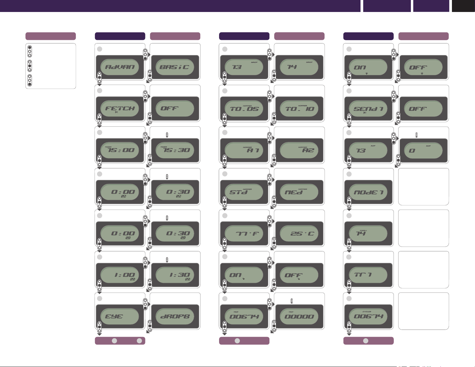
DUAL EXTERNAL LCD MENUS IN SAFE MODE
– BASIC MENU
FEATURE MENU
ALLOCATION
EXTERNAL
VIEW
EXTERNAL
ADJUST PARAMETER
MENU BASIC YES YES Basic/Adv
FETCH BASIC YES YES ON/OFF
TIMER BASIC YES YES 0.5-30min
A1 BASIC YES YES 0.5-30min
A2 BASIC YES YES 0.5-30min
A3 BASIC YES YES 0.5-30min
ANGEL EYE TEST BASIC NO YES Pass/Fail
VIEWABLE EXTERNAL MENU
The ANGEL has a number of features that may only be adjusted or viewed
on the LCD screen. The menu that is displayed can be split into two main
categories - Basic and Advanced. There is a division between basic and
advanced menus. As default, the menu divisions are factory set.
• This is a basic viewing menu that is designed for speed of use and allows you
to quickly view basic menu items; these are settings for the items you are
most likely to use whilst at a tournament.
• Any menu items that may change the performance of the ANGEL CANNOT be
adjusted externally e.g. Dwell, Trigger Offset and Mode.
FACTORY DEFAULT BASIC MENU SETTINGS
MENU
Allows you to select either Basic or Advanced menu options.
FETCH
Allows you to put your ANGEL in receiver mode so that it will receive data/
settings transmitted from other ANGEL markers or PDA’s.
TIMER, A1, A2, A3 FEATURE
This is a fully interactive game timer with 3 independent alarms and will allow
you and your team members to play in unison. The timer may be set in 30
second increments from 0 to 30 minutes. The 3 independent alarms may also
be set in 30 second increments giving you a very versatile game timer and
alarm system. Once the alarms are set they will be activated by the first trigger
pull after making the ANGEL LIVE.
ANGEL EYE TEST FEATURE – Whilst the ANGEL is in SAFE Mode.
• From the Basic or Advanced menu select Angel Eyes Test option using
the middle button externally or the blue button internally.
• Press the bottom button externally and the display will show ‘dropB’.
• Drop a paintball into the breech.
• When the paintball is detected the display will show ‘PASS’.
• Failure to obtain the ‘PASS’ message is an indication that the Angel
Eyes need cleaning or servicing.
DUAL EXTERNAL LCD MENUS IN SAFE MODE
– ADVANCED MENU
FEATURE MENU
ALLOCATION
EXTERNAL
VIEW
EXTERNAL
ADJUST PARAMETER
MENU ADV & BASIC YES YES Basic/Adv
FETCH ADV & BASIC YES YES ON/OFF
TIMER ADV & BASIC YES YES 0.5-30min
A1 ADV & BASIC YES YES 0.5-30min
A2 ADV & BASIC YES YES 0.5-30min
A3 ADV & BASIC YES YES 0.5-30min
ANGEL EYE TEST ADV & BASIC NO YES Pass/Fail
MROF ADVANCED YES YES 8-25bps
Hopper T Time ADVANCED YES YES 0.01-1.0 Secs
Hopper A Time ADVANCED YES YES 1-4 Shots
Hopper Type ADVANCED YES YES 1-16 Levels
TEMP ADVANCED YES YES °C / °F
VIBRATOR ADVANCED YES YES ON/OFF
TRIP ADVANCED YES YES Re-Zero
BACKLIGHT ADVANCED YES YES ON/OFF
SEND ADVANCED YES YES ON/OFF
ROF ADVANCED YES YES Re-Zero
MODE ADVANCED YES NO Where Applicable
DWELL ADVANCED YES NO 9-20m/s
TRIGGER OFFSET ADVANCED YES NO 1-20 Levels
CYCLES ADVANCED YES NO Non-Resetable
ID ADVANCED YES NO Non-Resetable
VIEWABLE EXTERNAL MENU
• This is an advanced viewing menu that allows you to view the full menu for the
items you are most likely to use whilst setting up your ANGEL.
• Any menu items that may change the performance of the ANGEL CANNOT be
adjusted externally e.g. Dwell, Trigger Offset and Mode.
FACTORY DEFAULT ADVANCED MENU SETTINGS
In addition to the seven items in the Basic menu, the Advanced menu contains
the following:
MROF
This allows you to tune your maximum rate of fire whilst the Angel Eyes modes
are OFF. The MROF should not be set greater than your loader is capable of
delivering. When the Angel Eyes are switched OFF the MROF is capped at 15.
HOPPER (LOADER) T TIME FEATURE
This allows the user to set the hopper (loader) activation time and is settable
from 0.1 to 2.0 seconds. This is the time period that the intellifeed will supply a
signal output for the hopper (loader).
HOPPER (LOADER) A ACTIVATION FEATURE
This allows the user to set the hopper (loader) activation point and can be set to
activate on the following;
A1 = Activates on every shot
A2 = Activates of a ROF of 2 shots or greater
A3 = Activates of a ROF of 3 shots or greater
A4 = Activates of a ROF of 4 shots or greater
HOPPER (LOADER) TYPE
This allows you to select the correct Angel Eye settings for the type of loader
that you are using. Once you have selected the correct setting the Angel Eyes
program will intelligently adjust itself to the variable speeds of your loader.
1-4 = 9v Agitator type loaders
5-8 = 12-18v Agitator type loaders
9-12 = Force-fed type loaders
13-16 = Only Very Fast force-fed type loaders (Ensure that your loader is at
maximum performance and reliability otherwise you may encounter problems
related to the loader)
TEMP FEATURE
This allows you to select Fahrenheit or Centigrade and monitors the
environmental temperature that the marker is exposed to.
VIBRATOR FEATURE
Should the game timer vibrator alarm function not be required this feature
allows you to disable the vibrator. The game timer will still function with the
vibrator disabled but no interactive alarms will activate.
TRIP FEATURE
This is a resettable shot counter that allows you to view the total number of
shots you have fired, and can be referred to at any stage, eg. per game, per day
or per event.
BACKLIGHT FEATURE
This allows you to switch the display backlight on/off.
SEND IR FEATURE
This allows you to switch on the infra red transmitter and be capable of
transmitting infra red data to other ANGELs. SEND IR will transmit the Game
Timer and its alarms information and will also switch on the vibrator and reset
the trip meter.
ROF FEATURE
This will record your highest rate of fire achieved shooting your ANGEL. The data
is constantly updated with the highest reading achieved should it exceed the
previous readings to ensure that you record the latest data. You can reset this
when necessary.
• Ensure a barrel blocking device is fitted to the ANGEL.
• Ensure the hopper is removed from the ANGEL.
• Ensure that there are no paintballs in the ANGEL.
WARNING ADHERE STRICTLY TO THESE
AND ALL OTHER SAFETY
INSTRUCTIONS AND GUIDELINES
• Ensure a barrel blocking device is fitted to the ANGEL.
• Ensure the hopper is removed from the ANGEL.
• Ensure that there are no paintballs in the ANGEL.
WARNING ADHERE STRICTLY TO THESE
AND ALL OTHER SAFETY
INSTRUCTIONS AND GUIDELINES