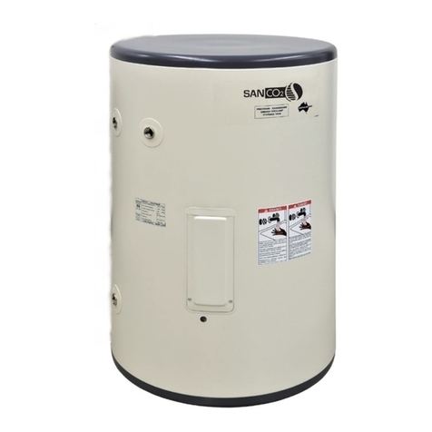
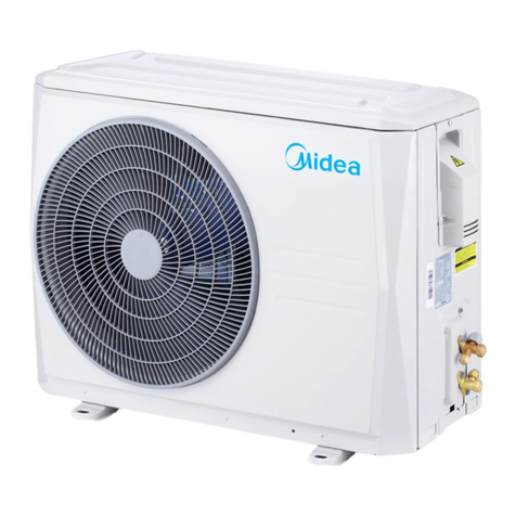
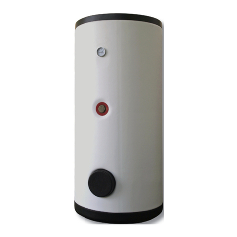
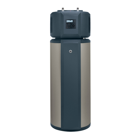
ECO2 Systems SANCO2 SAN-43SSAQA User manual

SANCO2Heat Pump – Owner’s Manual
Page 1 of 28
Sanden Heat Pump –Installation Manual
Page 1 of 40
.
Page title
Covering model numbers for residence
Heat Pump Unit GS3-45HPA-US
This appliance is not to be installed by unqualified and unlicensed persons,
please read and understand this manual prior to installing and operating the unit.
※This manual is for TO BE USED
by the installing Contractor
only.
20916702 (K)
Sanden Heat Pump –Owner’s Manual
Page 1 of 24
Page title
Covering model numbers for residence
Heat Pump Unit GS3-45HPA-US
This appliance is not to be installed by unqualified and
unlicensed persons, please read and understand this manual
prior to installing and operating the unit.
OOwwnneerr’’ss mmaannuuaall
Owner’s Manual
SANCO2Heat Pump Water Heater with Natural Refrigerant(CO2)
Heat Pump Units
Tanks
: GS4-45HPC
GS4-45HPC-D
: SAN-43SSAQA
SAN-83SSAQA
SAN-119GLBK
This appliance is not to be used by persons (including children) with reduced
physical, sensory or mental capabilities, or lack of experience and knowledge,
unless they have been given supervision or instruction.
Children being supervised not to play with the appliance.
This appliance is not to be installed by unqualied and
unlicensed persons, please read and understand this manual
prior to installing and operating the unit.

SANCO2Heat Pump – Owner’s Manual
Page 2 of 28
PATENTS
This water heater may be protected by one or more patents or registered designs in the name of ECO2 System LLC
TRADE MARKS
® Registered trademark of ECO2 Systems LLC
Note: Every care has been taken to ensure accuracy in preparation of this publication.
No liability can be accepted for any consequences that may arise as a result of its application.
Contents
Page title …………………………………………………………………………………………………… 1
Contents …………………………………………………………………………………………………… 2
Introduction………………………………………………………………………………………………… 3
How It Works……………………………………………………………………………………………… 3
Installation Details ……………………………………………………………………………………… 8
Trouble Shooting Guide …………………………………………………………………………… 9
Error Codes ……………………………………………………………………………………………… 10
Filling the System & Bleeding Air ……………………………………………………………… 11
Mains Power/Electrical Installation …………………………………………………………… 12
Electrical Connections ……………………………………………………………………………… 12
How to Connect Main Power …………………………………………………………………… 13
How to Connect Thermistor Cable …………………………………………………………… 14
Standard System Operation ……………………………………………………………………… 14
System Operation If Connected to Dry Contact ………………………………………… 15
Water Supply Quality ………………………………………………………………………………… 16
Technical Data …………………………………………………………………………………………… 17
Warranty Policy ………………………………………………………………………………………… 19
Registration for Warranty …………………………………………………………………………… 24
Memo ………………………………………………………………………………………………………… 25

SANCO2Heat Pump – Owner’s Manual
Page 3 of 28
Sanden Heat Pump – Owner’s Manual
Page 3 of 20
Introduction
The Sanden Heat Pump Water Heater System has been designed using the latest
refrigeration technology to remove the heat from the air to heat water. The refrigerant we
use is CO
2
which does not contribute to global warming so it allows us to help keep a clean
healthy earth for future generations.
We have also considered the power requirement. By using CO
2
as the refrigerant we have
produced one of the most energy efficient units currently available. It’s even more efficient
when connected to off-peak power
and the noise level is so low it will operate
unobtrusively throughout the night.
How it works
The Heat Pump Water Heater System heats water by transferring the heat from the
surrounding air to the water using a refrigerant. The refrigerant is heated by a heat
exchanger that absorbs heat from the surrounding air (Figure 1).
Figure 1: Heat Pump Water Heater System
Note: Operating conditions may vary depending on the type of off-peak tariff that is
available in your area. The unit must have a minimum of 5 hours continuous power
available at all time to allow the unit to operate without affecting reliability.
63
Sanden Heat Pump –Owner’s Manual
Page 3 of 24
Introduction
The Sanden Sanco2 Heat Pump Water Heater System has been designed using the latest
refrigeration technology to remove the heat from the air to heat water. The refrigerant used
is CO2 which does not contribute to global warming so it allows us to help keep a clean
healthy earth for future generations.
We have also considered the power requirement. By using CO2 as the refrigerant, we have
produced one of the most energy efficient units currently available. It is even more efficient
when connected to demand response power and the noise level is so low it will operate
unobtrusively throughout the night.
How it works
The Sanden Sanco2 Heat Pump Water Heater System heats water by transferring the heat
from the surrounding air to the water using a refrigerant. The refrigerant is heated by a
heat exchanger that absorbs heat from the surrounding air (Figure 1).
Figure 1: Heat Pump Water Heater System
Note:
The unit must have a minimum of 5 hours continuous power available at all time to allow
the unit to operate without affecting reliability.
SANCO2
How It Works
Air bleeding valves
145°F
(63°C)-
Cold Water & Hot Water Connections on Tank shown are only 3/4" NPT size on SAN-
43SSAQA & SAN-83SSAQA Tanks

SANCO2Heat Pump – Owner’s Manual
Page 4 of 28
■The extent of the possible harm or damage caused by misuse of the product falls into the following classications.
Danger Indicates an imminently hazardous situation that will result in death
or serious injury in case it is not avoided.
Warning The column with this classication indicates “the extent of harm that
includes the possibility of death or serious injury”.
Caution The column with this classication indicates “the extent of harm/damage
that includes the possibility of injury or damage to property”.
■The type of content to be observed can be explained with the following pictorial classications.
Indicates content requiring “attention”.
Indicates content that is prohibited.
Indicates content with “instructions” that need to be fully followed.
Sanden Heat Pump – Owner’s Manual
Page 4 of 20
Do not touch the tap while hot water is being
supplied
Hot water heater temperature over 125°F can cause severe burns instantly or death from scalding.
Children, disabled and elderly are at the highest risk of scalding.
Feel water temperature before bathing or showering.
Temperature Time to Produce a Serious Burn
120°F(49°C) More than 5minutes
125°F(52°C) 1-1/2 to 2minutes
130°F(54°C) About 30 seconds
135°F(57°C) About 10 seconds
140°F(60°C) Less than 5 seconds
145°F(63°C) Less than 3 seconds
150°F(66°C) About 1-1/2 seconds
155°F(68°C) About 1 second
Teble courtesy of Shriners Burn Institute
Danger
HOT!!
BURN

SANCO2Heat Pump – Owner’s Manual
Page 5 of 28
If the water heater has been subjected to re, ood, natural disasters or physical damage, DO NOT operate the
water heater again until it has been checked by a qualied service technician.
Failure to do so will cause injury.
Hydrogen gas can be produced in a hot water tank served by this water heater that has not been used for two
weeks or more. Hydrogen gas is extremely dangerous since it is ammable.
It is recommended to open the water faucet for few minutes before using any electrical appliance connected to
the hot water system.
If hydrogen gas is stored inside of a tank, there is a noise of air bleeding, in case that sound is heard, please do
not use re around the unit.
Sanden Heat Pump – Owner’s Manual
Page 4 of 20
Do not touch the tap while hot water is being
supplied
Do not touch the faucet while hot water is being
supplied.
Warning
Please wear gloves when you touch unit.

SANCO2Heat Pump – Owner’s Manual
Page 6 of 28
Sanden Heat Pump – Owner’s Manual
Page 5 of 20
LPG
・Please contact the Dealer about insulating the pipes.
・Contact the Dealer for repair.
Warning

SANCO2Heat Pump – Owner’s Manual
Page 7 of 28
Sanden Heat Pump – Owner’s Manual
Page 6 of 20
Check the installation conditions of the unit.
Installation of the unit in the following places could result
in accidents or failure and the performance of the unit
not being guaranteed.
· Anywhere the lowest temperature reached is below
minus 10 degrees centigrade
· Indoors (Applies only to the heat pump unit)
· Anywhere not completely flat, unstable or where
drainage is difficult
· Ensure not to put anything around the heat pump unit.
Could result in poor performance and unexpected
problems.
In the winter in particular please pay attention to any
snow coverage.
Could significantly i
nfluence performance and lead to failure.
Please select a place where noise an
d vibration while operating will
not bother your neighbours.
Could harmfully inuence performance and lead to failure.
Caution
· Wipe the unit with a soft dry cloth and do not use
chemical items when cleaning.
· Do not use gasoline, benzene, thinners, or any polishing
compounds.
Check the installation conditions of the unit.
Installation of the unit in the following places could result
in accidents or failure and the performance of the unit
not being guaranteed.
· Anywhere the lowest temperature reached is under
14 degrees Fahrenheit
· Indoors (Applies only to the heat pump unit)
· Anywhere not completely at, unstable or where
drainage is difcult
· Ensure not to put anything around the heat pump unit.
Could result in poor performance and unexpected problems.
In the winter in particular please pay attention to any
snow coverage.

SANCO2Heat Pump – Owner’s Manual
Page 8 of 28
Sanden Heat Pump –Installation Manual
Page 4 of 40
Installation details
This Sanden SANCO₂ Heat Pump Water Heater System must be installed by licensed
personnel in accordance with local building codes:
Installing contractor should be licensed by applicable state/province and municipal
authorities to install an Electrical & Plumbing product.
The unit has been designed for heating potable domestic hot water. Any other
usage, such as use for DHW in combination with space heating requires both a
heat exchanger suitable for local codes to be installed on the system to separate
potable and non-potable water and consultation with Sanden.
The unit is designed to operate when connected to the water supply with a
maximum operating pressure of 95PSI (655 kPa). To ensure the mains pressure
does not exceed this, first check incoming cold water mains pressure, and then a
pressure regulating device must be connected to the water supply line.
This system delivers hot water exceeding 120 oF (50 oC).
Installation of a temperature tempering device is MANDATORY to avoid potential
scalds and burns.
The unit must be stored and transported in an upright position. Failure to do so may
render the unit faulty. Such failure is not covered under any warranty agreements.
Failure to comply with the above conditions will void the warranty.
ECO2 Systems.
Sanden Heat Pump –Owner’s Manual
Page 7 of 24
Installation details
This Sanden Eco Hot water Heat Pump System must be installed by licensed personnel in
accordance with local building codes:
Installing contractor should be licensed by applicable state/province and municipal
authorities to install an Electrical & Plumbing product.
The unit has been designed for heating potable domestic hot water and any other
usage, such as space heating requires a heat exchanger suitable for local codes to
be installed on the system to separate potable and non-potable water.
The unit is designed to operate when connected to the water supply with a
maximum operating pressure of 95PSI (655 kPa). To ensure the mains pressure
does not exceed this, first check incoming cold water mains pressure, and then a
pressure regulating device must be connected to the water supply line.
This system delivers hot water exceeding 120 oF (50 oC).
Installation of a temperature tempering device is MANDATORY to avoid potential
scalds and burns.
The unit must be stored and transported in an upright position. Failure to do so may
render the unit faulty. Such failure is not covered under any warranty agreements.
Failure to comply with the above conditions will void the warranty.
California Proposition 65 WARNING
This product contains chemicals known to the State of California to cause
cancer, birth defects or other reproductive harm.
Sanden Heat Pump –Installation Manual
Page 4 of 40
Installation details
This Sanden SANCO₂ Heat Pump Water Heater System must be installed by licensed
personnel in accordance with local building codes:
Installing contractor should be licensed by applicable state/province and municipal
authorities to install an Electrical & Plumbing product.
The unit has been designed for heating potable domestic hot water. Any other
usage, such as use for DHW in combination with space heating requires both a
heat exchanger suitable for local codes to be installed on the system to separate
potable and non-potable water and consultation with Sanden.
The unit is designed to operate when connected to the water supply with a
maximum operating pressure of 95PSI (655 kPa). To ensure the mains pressure
does not exceed this, first check incoming cold water mains pressure, and then a
pressure regulating device must be connected to the water supply line.
This system delivers hot water exceeding 120 oF (50 oC).
Installation of a temperature tempering device is MANDATORY to avoid potential
scalds and burns.
The unit must be stored and transported in an upright position. Failure to do so may
render the unit faulty. Such failure is not covered under any warranty agreements.
Failure to comply with the above conditions will void the warranty.
Installation Details
if the Cold
Water mains pressure is above 75 PSI.
Sanden Heat Pump –Installation Manual
Page 4 of 40
Installation details
This Sanden SANCO₂ Heat Pump Water Heater System must be installed by licensed
personnel in accordance with local building codes:
Installing contractor should be licensed by applicable state/province and municipal
authorities to install an Electrical & Plumbing product.
The unit has been designed for heating potable domestic hot water. Any other
usage, such as use for DHW in combination with space heating requires both a
heat exchanger suitable for local codes to be installed on the system to separate
potable and non-potable water and consultation with Sanden.
The unit is designed to operate when connected to the water supply with a
maximum operating pressure of 95PSI (655 kPa). To ensure the mains pressure
does not exceed this, first check incoming cold water mains pressure, and then a
pressure regulating device must be connected to the water supply line.
This system delivers hot water exceeding 120 oF (50 oC).
Installation of a temperature tempering device is MANDATORY to avoid potential
scalds and burns.
The unit must be stored and transported in an upright position. Failure to do so may
render the unit faulty. Such failure is not covered under any warranty agreements.
Failure to comply with the above conditions will void the warranty.
75PSI (520 kPa).

SANCO2Heat Pump – Owner’s Manual
Page 9 of 28
Sanden Heat Pump – Owner’s Manual
Page 9 of 20
Trouble Shooting Guide
If you are faced with a problem in using our Hot Water Heat Pump system, please check
the following items, before seeking professional help.
For those problems not listed in the list above, an inspection provided by a skilled engineer
is required. Please contact your local Dealer.
Caution:
Do not turn off the electricity supplied to the heat pump system even if you go away from
home and do not use hot water for a long while.
If the system is equipped with freeze protect heaters, also do not turn off the power supply
to the heaters.
Failure to do so may cause the pipes to crack, due to freezing.
Status Considerable Causes Action to Take
No hot water
comes out of
water tap
Temperature
of hot water is
too low
Small or no hot water is left in
the storage tank.
- Stop using hot water and wait for about 1
hour
- Consider a change of the electricity
supply off-peak mode (Length of power-
supply hours may be too short for the
water heating cycle to cover the hot water
consumption)
Air removing procedure from the
heat pump system may be
insufficient.
- Open the water drain plugs on the Heat
Pump Unit to remove air from water circuit.
(Be careful for burning)
Filter on cold inlet connector may
be blocked.
- Check the filter and remove if there is any
blockage
Water flow speed may be
dropped due to the heat pump
piping bend, blockage or crush.
- Check for any piping bend or crush and
remove if any
Pipes may be frozen. - If frozen area is found on the piping, melt
the ice on the pipe and provide a heat
insulation
Stop valve is closed. - Open the valve
Air absorption is not sufficient
due to a blockage on the
evaporator.
-Remove the object blocking the air flow
through the evaporator
(e.g. fallen leaves, grass, snow, etc.)
For those problems not listed in the list above, an inspection provided by a skilled engineer is
required. Please contact your local distributor.
Caution:
Do not shut the electricity supplied to the Heat Pump system off even if you go away from home
and do not use hot water for a long while.
If the system is equipped with freeze protection heaters, also do not shut the power supply to the
heaters.
Failure to do so may cause a crack on the pipes due to the pipes getting frozen.
Sanden Heat Pump –Owner’s Manual
Page 8 of 24
Trouble shooting guide
If you face a problem while using our Heat Pump water heater system, please check the
following table prior to calling for support.
For those problems not listed above, an inspection provided by a skilled engineer is
required. Please contact the distributor.
Caution:
Do not shut the electricity supplied to the Heat Pump system off even if you go away from
home and do not use hot water for a long while.
If the system is equipped with freeze protect heaters, also do not shut the power supply to
the heaters.
Failure to do so may cause a crack on the pipes due to the pipes getting frozen.
Status
Considerable Causes
Action to Take
No hot water
comes out of
water tap
Temperature
of hot water is
too low
Small or no hot water is left in
the storage tank.
- Stop using hot water and wait for about 1
hour
- Consider a change of the electricity
supply off-peak mode (Length of power-
supply hours may be too short for the
water heating cycle to cover the hot water
consumption)
Air removing procedure from the
heat pump system may be
insufficient.
- Open the water drain plugs on the Heat
Pump Unit to remove air from water circuit.
(Be careful for burning)
Filter on cold inlet connector may
be blocked.
- Check the filter and remove if there is any
blockage
Water flow speed may be
dropped due to the heat pump
piping bend, blockage or crush.
- Check for any piping bend or crush and
remove if any
Pipes may be frozen.
- If frozen area is found on the piping, melt
the ice on the pipe and provide a heat
insulation
Stop valve is closed.
- Open the valve
Air absorption is not sufficient
due to a blockage on the
evaporator.
-Remove the object blocking the air flow
through the evaporator
(e.g. fallen leaves, grass, snow, etc.)
bleeding
bleed air from water circuit.
Sanden Heat Pump –Installation Manual
Page 4 of 40
Installation details
This Sanden SANCO₂ Heat Pump Water Heater System must be installed by licensed
personnel in accordance with local building codes:
Installing contractor should be licensed by applicable state/province and municipal
authorities to install an Electrical & Plumbing product.
The unit has been designed for heating potable domestic hot water. Any other
usage, such as use for DHW in combination with space heating requires both a
heat exchanger suitable for local codes to be installed on the system to separate
potable and non-potable water and consultation with Sanden.
The unit is designed to operate when connected to the water supply with a
maximum operating pressure of 95PSI (655 kPa). To ensure the mains pressure
does not exceed this, first check incoming cold water mains pressure, and then a
pressure regulating device must be connected to the water supply line.
This system delivers hot water exceeding 120 oF (50 oC).
Installation of a temperature tempering device is MANDATORY to avoid potential
scalds and burns.
The unit must be stored and transported in an upright position. Failure to do so may
render the unit faulty. Such failure is not covered under any warranty agreements.
Failure to comply with the above conditions will void the warranty.

SANCO2Heat Pump – Owner’s Manual
Page 10 of 28
Error
code Error contents
E1 Main PCB error
E2 Control PCB error
E6 Compressor booting error
E7 Fan motor locked
E8 High inlet current error
E9 Water circulation pump error
EC High water outlet error
F3 Discharged temperature error
F5 Communication error between main PCB
to control PCB
FA High pressure side error
H0 High water outlet error
H3 Pressure switch error
H6 Compressor revolution error
H7 Tank temperature thermistor error
H8 Current error
Sanden Heat Pump – Owner’s Manual
Page 10 of 20
Error Codes
When an error has occurred, a red LED on the operation panel turns on and an error code
is displayed on the LED display. The panel does not turn to the display sleep mode while
the error code is shown.
Figure 3 Error Code example
Below is the list of the error codes. If the corrective action does not solve the error problem,
a malfunction of the PCB is highly likely.
Error
code
Error contents
Error
code
Error contents
H9 HP ambient(outdoor)
temperature thermistor error F5 Communication error between main
PCB to control PCB
HC HP water outlet(outgoing)
temperature thermistor error E8 High inlet current error
J3 HP discharge temperature
thermistor error H8 Current error
J5 HP suction temperature thermistor
error L4 High temperature of module error
J6 HP defrost temperature thermistor
error L5 High outlet current error
J8 HP water inlet(return)
temperature thermistor error P4 Module temperature thermistor
error
H7 Tank temperature thermistor error U2 High voltage error
E6 Compressor booting error HJ Water circuit error
H6 Compressor revolution error EC High water outlet error
U0 Refrigerant leakage error E9 Water circulation pump error
E1 Main PCB error E7 Fan motor locked
E2
L7 Control PCB error F3 Discharged temperature error
Error
code Error contents
H9 HP ambient(outdoor) temperature
thermistor error
HC HP water outlet(outgoing) temperature
thermistor error
HJ Water circuit error
J3 HP discharge temperature thermistor
error
J5 HP suction temperature thermistor error
J6 HP defrost temperature thermistor error
J8 HP water inlet(return) temperature
thermistor error
L4 High temperature of module error
L5 High outlet current error
L7 Control PCB error
P4 Module temperature thermistor error
U0 Refrigerant leakage error
U2 High voltage error

SANCO2Heat Pump – Owner’s Manual
Page 11 of 28
The following steps must be taken to ensure all air is bled from the system.
Incorrect bleeding of air may cause the water temperature to vary during operation.
Ensure that all piping to tank unit and heat pump unit are installed and
connections are tight, then open the Cold Water Supply Valve to the system.
Push up the lever on the PR valve to open, and ll the tank unit with water.
Conrm that water comes out of the relief valve, and then close the lever.
Open the hot water faucets to bleed air from the house piping system.
Close the faucets after no air is seen in the water.
Open the 3 x water bleed screws on the heat pump unit.
Close the plugs after no air is seen in the water.
Leave the hot water faucets open for 3 minutes.
Close the faucet after no air can be seen in the water.
Supply power to the heat pump unit.
Display shows "1200" then "Clock setting mode" is started with operating "Air bleeding
process" at the same time.
In case nish time setting or nothing is operated for 1 minute, "Clock setting mode" is
terminated and "APon" will be displayed on the monitor.
"Air bleeding process" will be done in 5 minutes.
Once it's nished, current time will be shown on monitor.
Sanden Heat Pump – Owner’s Manual
Page 11 of 20
Removing air from the system
Please note:
Plumbing work should only be completed by a licensed plumber
• The following steps must be taken to ensure all air is removed from the system.
Incorrect removal of air may cause the water temperature to vary.
• Plumb pipes to the tank unit and the heat pump unit.
• Push up the lever on the PTR valve to open, and fill the tank unit with water.
• Confirm that the water comes out of the relief valve and then close the lever.
• Open the hot water taps in the home to remove air.
• Close the hot water taps in the home after no air is confirmed in the water.
• Open the water drain plug on the heat pump unit.
• Close the plug after no air is confirmed in the water.
• Connect the power to the heat pump unit.
• Air removing process (Refer to figure 4)
1. Switching to Air Removing Mode
Long press the “Up” and “Down” keys to switch to the “Heat Setting Mode”.
2. Press the “Up” or “Down” keys to switch to the “Air Removing Mode” and press
the “Enter” key. Press the “Up” keys again to display “APon”, then press the
“Enter” key.
After 5 minutes, the air removing mode will automatically finish and the display will
show [Air ] again.
• Open the hot water taps in the home to remove air.
• Close the hot water taps in the home after no air is confirmed in the water.
*Caution
If air removing mode is not completed, the system will not start the heating cycle.
Figure 4: Air removing process
PR valve lever
PR valve to open,
Figure 4: Air bleeding process
Open
The air bleeding valve
CAUTION : Be sure to follow the procedure below.
If the procedure is not followed, the pump may run idle and be damaged.
Filling the System & Bleeding Air
Open the faucet to bleed air. Close the faucet
after no air bubbles can be seen in the water.
Open the 3 x air bleeding screws on the Heat
Pump Unit.
Close the valve after no air is conrmed in the
water supply.
Then connect power to the Heat Pump Unit.
Open faucet.
CAUTION : One Air bleeding screw is located underneath the heat pump unit!

SANCO2Heat Pump – Owner’s Manual
Page 12 of 28
Sanden Heat Pump –Owner’s Manual
Page 11 of 24
Mains Power/Electrical Installation
All Electrical Wiring should be done in accordance with the latest edition of the
National Electrical Code (NEC) and all local State/Province and Municipality codes.
The power requirement for the system is a dedicated 15 amp circuit fitted with a
circuit breaker. This circuit may be connected to constant power or off-peak power.
A local disconnect should be installed adjacent to the Heat Pump unit in
accordance to NEC and local codes.
Installation of this system must be carried out only by a qualified installation
technician (electrical or plumbing).
Electrical connections
Breaker size and wiring must be sized per NEC rules for the rating plate amperage,
MCA and MOP or Max Circuit Breaker.
Power Supply is 208/230V-1Ph-60Hz
Verify that the tank unit is full of water and the
water shut off valves are open before turning on the
power.
How to connect Main Power
Remove the terminal block cover (Philips head screwdriver required)
Connect the power wiring to the terminal block per the wiring diagram/manual.
Ensure ground wire is connected.
Secure the power supply wiring below the terminal block with the screw clamp
fitting.
Attach the terminal block cover and piping cover back on the heat pump unit.
Electrical Connections

SANCO2Heat Pump – Owner’s Manual
Page 13 of 28
Sanden Heat Pump –Owner’s Manual
Page 11 of 24
Mains Power/Electrical Installation
All Electrical Wiring should be done in accordance with the latest edition of the
National Electrical Code (NEC) and all local State/Province and Municipality codes.
The power requirement for the system is a dedicated 15 amp circuit fitted with a
circuit breaker. This circuit may be connected to constant power or off-peak power.
A local disconnect should be installed adjacent to the Heat Pump unit in
accordance to NEC and local codes.
Installation of this system must be carried out only by a qualified installation
technician (electrical or plumbing).
Electrical connections
Breaker size and wiring must be sized per NEC rules for the rating plate amperage,
MCA and MOP or Max Circuit Breaker.
Power Supply is 208/230V-1Ph-60Hz
Verify that the tank unit is full of water and the
water shut off valves are open before turning on the
power.
How to connect Main Power
Remove the terminal block cover (Philips head screwdriver required)
Connect the power wiring to the terminal block per the wiring diagram/manual.
Ensure ground wire is connected.
Secure the power supply wiring below the terminal block with the screw clamp
fitting.
Attach the terminal block cover and piping cover back on the heat pump unit.
How to Connect Main Power
Remove the power box cover (Philips head screwdriver required)
Connect the power wiring to the terminal block per the wiring diagram/manual.
Ensure ground wire is connected.
Secure the power supply wiring below the terminal block with the screw clamp tting.
Re attach the power box cover to the heat pump unit.
Figure 5: Connect power
0.5mm~1mm
Power wire
Core
·Heat Pump 208/230V Power Wiring must use solid copper wire.
·Appropriately sized ring or fork terminals are recommended for easier connection.
Power supply
208/230V
Black
White
Green/Yellow
Power line
Ground
5×M4 Screws
Wire holder band

SANCO2Heat Pump – Owner’s Manual
Page 14 of 28
Sanden Heat Pump –Owner’s Manual
Page 12 of 24
Figure 5: Power connection
System operation using continuous power
The system runs its water heating cycle once a day to fill up the storage tank unit
with heated water.
If the block out time function is selected the unit will not operate during the block out
times – this function is typically used on installations that have time of use electricity
tariffs.
The water heating cycle operation starts automatically when the residual hot water
in the tank unit is less than 40 gallons (150 litres).
The system will not run if the electrical power supply is cut off (i.e. if it is connected
to demand response power). However, the system will automatically start operation,
once the electric power is restored.
Power supply
208/230V
Wire holder band
Power line
Ground
How to Connect Thermistor Cable
Remove the piping cover.
Connect the thermistor cable line to the terminal block.
Fix the thermister cable with the code clip and conduit clip.
Attach the piping cover back on the heat pump unit.
Conduit clip
Code clip
Thermistor cable
White
Green
Green
Blue
Black
25mm
or
less
Standard System Operation
The system will not run if the power supply is cut off.

SANCO2Heat Pump – Owner’s Manual
Page 15 of 28
Sanden Heat Pump –Owner’s Manual
Page 13 of 24
System operation if connected to Demand Response power
There are no special settings for the Demand Response. The system will run once
power becomes available and the temperature in the tank drops below the set point
of the tank thermistor.
If connecting the unit to Demand Response power, ensure that the off peak tariff
provides a minimum of 5 hours continuous power, as it can take at least four hours
to fill the tank unit with hot water.
If the ambient temperature is lower than 50oF (10oC) this can be longer.
If the unit is connected to Demand Response power and hot water consumption has
been higher than normal, hot water might not be available until the next power
supply cycle.
Daily frequency and amount of hot water consumption may also affect the duration
of the heating cycle operation.
Select the electrical supply mode that best suits the customer’s hot water
consumption. The type of off-peak connection may need to be changed
if hot water supply is not maintained as required.
The basic system installation is now complete; the unit is now ready for initial filling,
air purge and then start up.
Check the Installation against the Installation Check list provided
at the end of this manual
Ensure that the work site is tidy; Sanden International recommends the use of Slim Duct or
Fortress product to cover water piping on the outside of the house
Caution
Use copper wiring
208/230V Power
Ground Wire
Breaker Box
Figure 6: Outline of electrical system connections
208/230V Power
Ground Wire
System Operation If Connected to Dry Contact
There are no special settings for the Dry contact input. The system will run once dry
contact input becomes available and the temperature in the tank drops below the set
point of the tank thermistor.
If the Unit is connected to Dry Contact and Hot Water consumption has been higher
than normal, hot water may not be available until the closure of the Dry Contact.
Daily frequency and amount of hot water consumption may also affect the duration of
the heating cycle operation.
Sanden Heat Pump –Owner’s Manual
Page 12 of 24
Figure 5: Power connection
System operation using continuous power
The system runs its water heating cycle once a day to fill up the storage tank unit
with heated water.
If the block out time function is selected the unit will not operate during the block out
times – this function is typically used on installations that have time of use electricity
tariffs.
The water heating cycle operation starts automatically when the residual hot water
in the tank unit is less than 40 gallons (150 litres).
The system will not run if the electrical power supply is cut off (i.e. if it is connected
to demand response power). However, the system will automatically start operation,
once the electric power is restored.
Power supply
208/230V
Wire holder band
Power line
Ground
bleeding and then start up.
ECO2 Systems LLC recommends the use of Slim Duct or

SANCO2Heat Pump – Owner’s Manual
Page 16 of 28
Sanden Heat Pump –Owner’s Manual
Page 14 of 24
Water Supply Quality (Supplemental)
Chloride and PH
In areas with a high concentration of chloride in the water, that water can cause
corrosion and subsequent failures. Where the chloride level exceeds 0.1 ounces per
gallons (200 mg/litre), the warranty is no longer valid on to the heat pump unit and tank
unit.
PH is a measure of whether the water is alkaline or acid. In an acidic water supply, the
water can attack the parts and cause them to fail.
No warranty coverage is given on the heat pump unit and tank unit where the PH is
less than 6.0.
Supply Water with a PH less than 6.0 may be treated to raise the PH.
It is recommended that an analysis of the Supply Water be conducted before
connecting the Heat pump unit to the system.
Figure 7 Chlorides and PH
Change of water supply
Changing, or alternating, from one water supply to another can have a detrimental
effect on the operation and/or life expectation of the water tank unit cylinder, PR valve,
water heating circulation and the heat exchanger in the system.
Where there is a changeover from one water supply to another, for example, a
rainwater tank supply, desalinated water supply, public recirculated water supply or
water brought in from another supply, then water chemistry information should be
sought from the supplier or the water should be tested to ensure it meets the warranty
requirements in this installation manual.
Water Supply Quality
Chloride, Water Hardness and pH
In high chloride water supply areas, the water can corrode some parts and cause them
to fail. Where the chloride level exceeds 0.1 ounces per gallons (200 mg/litre) or Water
Hardness level exceeds 0.1 ounces per gallons (200 mg/litre) warranty does not apply
to the heat pump unit and tank unit. pH is a measure of whether the water is alkaline or
acid. In an acidic water supply, the water can attack the parts and cause them to fail.
No warranty applies to the heat pump unit and tank unit where the pH is less than 6.5
or more than 8.0. The water supply from a rainwater tank unit in a metropolitan area is
likely to be corrosive due to the dissolution of atmospheric contaminants. Water with
a pH less than 6.5 may be treated to raise the pH. It is recommended that an analysis
of the water from a rainwater tank be conducted before connecting this type of water
supply to the system.

SANCO2Heat Pump – Owner’s Manual
Page 17 of 28
*SAN-119GLBK tank is a glass-lined steel tank with a 10 year warranty.
Note: Materials and specifications are subject to change without notice.
All dimensions displayed in inches. Heat Pump Stainless Steel
Storage Tank*
Eco2 Systems LLC
P.O. Box 1358, Walled Lake, MI 48390
Phone: 1-844-726-3262 or 1-844-SANDCO2
Email: info@sandenwaterheater.com
Website: www.sandenwaterheater.com
For more information, please call 1-844-SANDCO2 or email info@sandenwaterheater.com.
Specifications
35-1/4"11"
32-1/2"
3/4"
2-3/4"5"
4-3/4" 23" 4-3/4"
27-1/2
1/2"3-3/4"1/2"
14-1/4"
Sanden Dealer
YEAR
LABOR
0
C
Outdoor Unit (Heat Pump) Model No. GS3-45HPA-US
REV 011620
3
Specifi cations
Water Temperature Setting 130 ºF to 175 ºF
Ambient Air Operating Temperature -20ºF to +110ºF
Heat Pump Capacity 15,400 Btu/h
Heat Pump Capacity 4.5 kW
Heat Pump COP 5.2
Refrigerant Type R744 (CO2)
Compressor Type Inverter
Power Voltage 208/230v –1Ph – 60Hz
Breaker Size 15 Amps
MCA 13 Amps
Outdoor Operating Noise Level 37 dB
Weight 106 lbs
Pipe Size (Tank to Heat Pump) 1/2" (Hot & Cold)
Max Length Inc Vertical 50 ft
Max Vertical Separation 16 ft
Max Water Pressure 95 Psig
Performance 43-gal. sys. 83-gal. sys. 119-gal. sys.
Uniform Energy Factor 2.85 3.34 3.23
First Hour Rating 65 gallons 109 gallons 130 gallons
Tank Model No: SAN-43SSAQA SAN-83SSAQA SAN-119GLBK*
AHeight 38-
1
/
8
"68-
7
/
8
”63-
3
/
5”
BHot Water Outlet & PR Valve 29-
1
/
2
"60-
1
/
4
”56”
CHeat Pump Return 29-
1
/
2
"60-
1
/
4
”60-
1
/
4
"
DSensor Port 9-
3
/
4
" 40
3
/
8
”56”
E
Cold Water Inlet / Cold Water to HP
8-
3
/
4
"8-
3
/
4
”4”
FDiameter 24-
1
/
2
"24-
1
/
2
”28”
Weight (lbs) 88 lbs 115 lbs 345 lbs
Tank Capacity (gallons) 43 gallons 83 gallons 119 gallons
Warranty 15 years 15 years 10 years*
Connection Sizes
Cold Water Inlet
3
/
4
" NPT
Hot Water Outlet
3
/
4
" NPT
Cold Water to Heat Pump
3
/
4
" NPT
Hot Water Return from Heat Pump
3
/
4
” NPT
Pressure Relief Valve Setting (Psig)
125 Psig
*
Storage Tank Dimensions
Technical Data
(11/2" SAN-119GLBK)
(11/2" SAN-119GLBK)
125/150 Psig

SANCO2Heat Pump – Owner’s Manual
Page 18 of 28
Sanden Heat Pump –Owner’s Manual
Page 17 of 24
GS3-45HPA-US Dimensions
Specification
Refrigerant type
R744(CO2)
Mass volume
22 oz. (650g)
Setting Outlet water temp
130~175°F
Product weight
106lb (48 kg)
Thermal capacity
4.5 kw
Fan motor FLA
0.3A , 70W
Water pump FLA
0.2A , 30W
Compressor RLA / LRA
7.5 / 9.8A
MCA
13A
Circuit Breaker Size
15A
Design Pressure(High / Low)
1885 /1059 PSI
Max inlet water temperature
110°F
Protection Raining Class
IPX4
Max, Operating water Pressure
700kPa
GS4-45HPC/GS4-45HPC-D Dimensions
Refrigerant type R744(CO2)
Mass volume 25.4oz (720g)
Setting Outlet water temp 145/150°F
Product weight GS4-45HPC 108lb (49kg)
GS4-45HPC-D 110lb (50kg)
Thermal capacity 4.5 kw
Power consumption of drain pan heater ※132W
Fan motor FLA 0.3A / 30W
Water pump FLA 0.6A / 60W
Compressor RLA / LRA 5.0A / 9.0A
MCA 7.2A
Circuit Breaker Size 15A
Design Pressure(High/Low) 1740/1160 PSI
Max inlet water temperature 100°F
Protection Raining Class IPX4
Max, Operating water Pressure 125 Psig
2.7”32.48”0.91”
1.02”
14.02”
1.18”
12.88”
2.95”
4.82”
16.24”
3.86”
DRAIN CONNECTOR
HP INLET (COLD WATER) PT1/2 HP OUTLET (HOT WATER) PT1/2
4.82” 22.83”
2.39”0.88” 11.81”
25.94”0.63”
26.57”
5.85” 1.08”
Unit:inch
2.76”
9.89”14.2”
5.91”
1.41”
※GS4-45HPC-D only

SANCO2Heat Pump – Owner’s Manual
Page 19 of 28
Sanden Heat Pump –Owner’s Manual
Page 17 of 24
GS3-45HPA-US Dimensions
Specification
Refrigerant type
R744(CO2)
Mass volume
22 oz. (650g)
Setting Outlet water temp
130~175°F
Product weight
106lb (48 kg)
Thermal capacity
4.5 kw
Fan motor FLA
0.3A , 70W
Water pump FLA
0.2A , 30W
Compressor RLA / LRA
7.5 / 9.8A
MCA
13A
Circuit Breaker Size
15A
Design Pressure(High / Low)
1885 /1059 PSI
Max inlet water temperature
110°F
Protection Raining Class
IPX4
Max, Operating water Pressure
700kPa
1 | Page
SANCO2 Warranty Policy 12-01-2020
Residential Warranty Policy covering the following Model #’s :
Heat Pump : GS4-45HPC
Storage Tanks : SAN-43SSAQA, SAN-83SSAQA, SAN-119GLBK
Warranty Conditions as of December 1st 2020 to the Original Owner Only
1. Warranty period
Subject to the Warranty Conditions and Exclusions stated below, the Eco2 Systems LLC Heat
Pump Water Heater System with the corresponding model numbers warranted in Residential /
Combi DHW & Heating applications ONLY (For Commercial applications as defined the
warranty is covered in a separate document) as follows:
1-1. Residential DHW application ; Heat Pump unit
Eco2 Systems LLC warrants all parts & labor on the SANCO₂system for a period of 3 years
from date of installation and a further 7 years on Parts only excluding shipping costs.
Labor costs are paid per the payment cost schedule published by Eco2 Systems LLC and
revised from time to time at Eco2 Systems LLC’s requirement (Exhibit A).
Should at any time during the 10 year Parts warranty any component directly part of the CO₂
refrigerant circuit fail, where replacement of that component would require opening of the
refrigerant circuit, Eco2 Systems LLC will replace the Heat Pump unit in it’s entirety. If this failure
occurs in the first 3 years of operation, then Labor costs will be paid per Exhibit A.
1-2. Residential DHW application ; Tank
Eco2 Systems LLC warrants that the SAN-43SSAQA, SAN-83SSAQA tanks will be free from
defects for 10 years at 100% replacement, and for a further 5 years under a pro-rated scale,
culminating in warranty ending after 15 years from date of installation.
Failure in Year 11: 80% of replacement value
Failure in Year 12: 60% of replacement value
Failure in Year 13: 40% of replacement value
Failure in Year 14: 20% of replacement value
SAN-119GLBK tanks have a warranty of 10 years only at 100% replacement value.
2 | Page
SANCO2 Warranty Policy 12-01-2020
1-3. Combined DHW/Heating application
When used in a Combined DHW/Heating System application providing that the winter design
(99%) temperature must be above 22˚F and with a single heat pump unit serving a heating load
of less than 10,000 Btu/h in addition to a minimum DHW demand of 20 Gallons per day then the
warranty period will be amended to that stated below.
1-3.1. Combined DHW/Heating application ; Heat Pump unit
Eco2 Systems LLC warrants all parts & labor on the SANCO₂combi system for a period of 2
years from date of installation and a further 5 years on Parts only excluding shipping costs.
Labor costs are paid per the payment cost schedule published by Eco2 Systems LLC and
revised from time to time at Eco2 Systems LLC’s requirement.
1-3.2. Combined DHW/Heating application ; Tank
The Storage tank warranty period is unaffected by the usage in a Combined DHW/Heating
system and remains unchanged from the warranty period stated previously.
2. Warranty Conditions – All Residential Applications
2-1. The Eco2 Systems LLC Heat Pump Water Heater System must be installed in accordance with
the installation instructions supplied with the Heat Pump Water Heater System, all relevant
industry practices and in accordance with all applicable relevant plumbing codes plus
statutory/local requirements of the state/province/municipality of the location where the water
heater is installed.
2-2. Where a failed component or Heat Pump Water Heater System is replaced under warranty, the
balance of the original warranty period will remain effective. The replaced part or complete new
Heat Pump Water Heater System does not carry a new warranty.
2-3. Warranty period only applies from the verified date of system installation, if such a date cannot
be verified then the warranty will be deemed to have started using a date calculated after 2 (two)
months have elapsed from the date of unit manufacture.
Heat Pumps : GS4-45HPC/GS4-45HPC-D

SANCO2Heat Pump – Owner’s Manual
Page 20 of 28
2 | Page
SANCO2 Warranty Policy 12-01-2020
1-3. Combined DHW/Heating application
When used in a Combined DHW/Heating System application providing that the winter design
(99%) temperature must be above 22˚F and with a single heat pump unit serving a heating load
of less than 10,000 Btu/h in addition to a minimum DHW demand of 20 Gallons per day then the
warranty period will be amended to that stated below.
1-3.1. Combined DHW/Heating application ; Heat Pump unit
Eco2 Systems LLC warrants all parts & labor on the SANCO₂combi system for a period of 2
years from date of installation and a further 5 years on Parts only excluding shipping costs.
Labor costs are paid per the payment cost schedule published by Eco2 Systems LLC and
revised from time to time at Eco2 Systems LLC’s requirement.
1-3.2. Combined DHW/Heating application ; Tank
The Storage tank warranty period is unaffected by the usage in a Combined DHW/Heating
system and remains unchanged from the warranty period stated previously.
2. Warranty Conditions – All Residential Applications
2-1. The Eco2 Systems LLC Heat Pump Water Heater System must be installed in accordance with
the installation instructions supplied with the Heat Pump Water Heater System, all relevant
industry practices and in accordance with all applicable relevant plumbing codes plus
statutory/local requirements of the state/province/municipality of the location where the water
heater is installed.
2-2. Where a failed component or Heat Pump Water Heater System is replaced under warranty, the
balance of the original warranty period will remain effective. The replaced part or complete new
Heat Pump Water Heater System does not carry a new warranty.
2-3. Warranty period only applies from the verified date of system installation, if such a date cannot
be verified then the warranty will be deemed to have started using a date calculated after 2 (two)
months have elapsed from the date of unit manufacture.
3 | Page
SANCO2 Warranty Policy 12-01-2020
2-4. Where the Heat Pump Water Heater System is installed in a position that does not allow safe
operating practices, such as not installing a properly size metal drain pan if installed in an area
where leakage from the tank or it’s connections would result in damage to the area adjacent to
the heat pump or the storage tank.
2-5. The cost of accessing the site safely, including the cost of additional materials handling and/or
safety equipment, shall be the owner's responsibility.
2-6. The warranty only applies to the Heat Pump Water Heater System (heat pump & storage tank)
and original or genuine (company) component replacement parts and therefore does not cover
any plumbing or electrical parts supplied by the installer and not an integral part of the Heat
Pump Water Heater System. Such parts would include but not limited to; pressure regulating
valves, isolation valves, solenoid valves, electrical switches, pumps, trace heating, fuses or any
other field supplied parts used in the installation of the Eco2 Systems LLC Heat Pump Water
Heater System.
2-7. The Heat Pump Water Heater System must be sized to the hot water demand in accordance
with the guidelines in the current Eco2 Systems LLC Heat Pump Water Heater System literature
and application guides and training information.
2-8. This warranty is for parts only, any and all labor costs associated with diagnosis, removal of the
faulty part and installation of replacement parts will solely be the owner’s responsibility except
where covered by the labor warranty section of this warranty.
3. Warranty Exclusions
Repair and replacement work will be carried out as set out in the Eco2 Systems LLC Heat Pump
Water Heater System warranty. However the following exclusions may void the warranty and
may incur additional service charges and/or cost of parts:
3-1. Accidental damage to the Heat Pump Water Heater System or any component, including: Acts
of God, failure due to misuse, incorrect installation, attempts to repair the water heater other
than by an Eco2 Systems LLC accredited service agent or the Eco2 Systems LLC service dept.
This manual suits for next models
4
Table of contents
Other ECO2 Systems Water Heater manuals
Popular Water Heater manuals by other brands

Viessmann
Viessmann VITOCELL 300B Installation and service instructions

A.O. Smith
A.O. Smith HSE-SBS 6 user guide

Unical
Unical SERBHA 300 Installation and maintenance instructions
Magontec
Magontec CORREX MP 1.9-900 operating instructions
andrews
andrews 32/143 Installation guide, operation and service manual

A.O. Smith
A.O. Smith 710 ASME Service manual

OSO HOTWATER
OSO HOTWATER Delta Coil DC120 installation manual
Haier
Haier FCD-JTHC100A-III (E) user manual

Heatworks
Heatworks MODEL 3 User manual & installation guide
aldes
aldes T.Flow Hygro+ installation instructions

Noritz
Noritz GQ-2457WS US owner's guide

Wijas
Wijas POW-LCD 12 Installation and operation manual
