ECO2 Systems SANCO2 GS4-45HPC User manual
SANCO2Heat Pump – Installation Manual
Page 1 of 44
Sanden Heat Pump –Installation Manual
Page 1 of 40
.
Page title
Covering model numbers for residence
Heat Pump Unit GS3-45HPA-US
This appliance is not to be installed by unqualified and unlicensed persons,
please read and understand this manual prior to installing and operating the unit.
※This manual is for TO BE USED
by the installing Contractor
only.
20916710 (K)
Installation Manual
SANCO2Heat Pump Water Heater with Natural Refrigerant(CO2)
Heat Pump Unit
Tanks
: GS4-45HPC
: SAN-43SSAQA
SAN-83SSAQA
SAN-119GLBK
※This manual is for TO BE USED by the installing Contractor only.

SANCO2Heat Pump – Installation Manual
Page 2 of 44
PATENTS
This water heater may be protected by one or more patents or registered designs in the name of ECO2 Systems LLC
TRADE MARKS
® Registered trademark of ECO2 Systems LLC
Note: Every care has been taken to ensure accuracy in preparation of this publication.
No liability can be accepted for any consequences that may arise as a result of its application.
Contents
Page title …………………………………………………………………………………………………… 1
Contents …………………………………………………………………………………………………… 2
Introduction………………………………………………………………………………………………… 3
How It Works……………………………………………………………………………………………… 3
Installation Details ……………………………………………………………………………………… 4
Installation Location …………………………………………………………………………………… 5
Heat Pump Unit Installation ……………………………………………………………………… 6
Water Piping Installation
-
Heat Pump Unit & Tank …………………………………… 7
Heat Pump Unit Water Piping …………………………………………………………………… 9
Mains Power/Electrical Installation …………………………………………………………… 10
Electrical Connections ……………………………………………………………………………… 10
How to Connect Main Power……………………………………………………………………… 10
How to Connect Tank Thermistor Cable to Heat Pump Unit ……………………… 12
Standard System Operation ……………………………………………………………………… 15
System Operation If Connected to Dry Contact ………………………………………… 15
How to Connect Dry Contact……………………………………………………………………… 16
Filling the System & Bleeding Air ……………………………………………………………… 17
Freeze Protection ……………………………………………………………………………………… 18
Commissioning Mode ………………………………………………………………………………… 21
How to Switch to Commissioning Mode …………………………………………………… 21
Error Codes ……………………………………………………………………………………………… 26
Water Supply Quality ………………………………………………………………………………… 29
Technical Data …………………………………………………………………………………………… 30
Wiring Diagram ………………………………………………………………………………………… 33
Warranty Policy ………………………………………………………………………………………… 34
Check Sheet ……………………………………………………………………………………………… 40
Replace Controller Assembly …………………………………………………………………… 41
Memo ………………………………………………………………………………………………………… 42
SANCO2Heat Pump – Installation Manual
Page 3 of 44
Sanden Heat Pump –Installation Manual
Page 3 of 40
Introduction
The Sanden SANCO₂ Heat Pump Water Heater System has been designed using the
latest refrigeration technology to remove the heat from the air to heat water. The
refrigerant we use is CO2 which does not contribute to global warming so it allows us to
help keep a clean healthy earth for future generations.
By using CO2 as the refrigerant, we have produced one of the most energy efficient units
currently available. It is even more efficient when connected to demand response power
and the noise level is so low it will operate unobtrusively at any time.
How it works
The Sanden SANCO₂ Heat Pump Water Heater System heats water by transferring the
heat from the surrounding air to the water using a refrigerant. The refrigerant is heated by
a heat exchanger that absorbs heat from the surrounding air (Figure 1).
Figure 1: Heat Pump Water Heater System
Note:
The unit must have a minimum of 5 hours continuous power available at all time to allow
the unit to operate without affecting reliability.
How It Works
Air bleeding
valves

SANCO2Heat Pump – Installation Manual
Page 4 of 44
Sanden Heat Pump –Installation Manual
Page 4 of 40
Installation details
This Sanden SANCO₂ Heat Pump Water Heater System must be installed by licensed
personnel in accordance with local building codes:
Installing contractor should be licensed by applicable state/province and municipal
authorities to install an Electrical & Plumbing product.
The unit has been designed for heating potable domestic hot water. Any other
usage, such as use for DHW in combination with space heating requires both a
heat exchanger suitable for local codes to be installed on the system to separate
potable and non-potable water and consultation with Sanden.
The unit is designed to operate when connected to the water supply with a
maximum operating pressure of 95PSI (655 kPa). To ensure the mains pressure
does not exceed this, first check incoming cold water mains pressure, and then a
pressure regulating device must be connected to the water supply line.
This system delivers hot water exceeding 120 oF (50 oC).
Installation of a temperature tempering device is MANDATORY to avoid potential
scalds and burns.
The unit must be stored and transported in an upright position. Failure to do so may
render the unit faulty. Such failure is not covered under any warranty agreements.
Failure to comply with the above conditions will void the warranty.
SANCO2.
Sanden Heat Pump –Owner’s Manual
Page 7 of 24
Installation details
This Sanden Eco Hot water Heat Pump System must be installed by licensed personnel in
accordance with local building codes:
Installing contractor should be licensed by applicable state/province and municipal
authorities to install an Electrical & Plumbing product.
The unit has been designed for heating potable domestic hot water and any other
usage, such as space heating requires a heat exchanger suitable for local codes to
be installed on the system to separate potable and non-potable water.
The unit is designed to operate when connected to the water supply with a
maximum operating pressure of 95PSI (655 kPa). To ensure the mains pressure
does not exceed this, first check incoming cold water mains pressure, and then a
pressure regulating device must be connected to the water supply line.
This system delivers hot water exceeding 120 oF (50 oC).
Installation of a temperature tempering device is MANDATORY to avoid potential
scalds and burns.
The unit must be stored and transported in an upright position. Failure to do so may
render the unit faulty. Such failure is not covered under any warranty agreements.
Failure to comply with the above conditions will void the warranty.
California Proposition 65 WARNING
This product contains chemicals known to the State of California to cause
cancer, birth defects or other reproductive harm.
Sanden Heat Pump –Installation Manual
Page 4 of 40
Installation details
This Sanden SANCO₂ Heat Pump Water Heater System must be installed by licensed
personnel in accordance with local building codes:
Installing contractor should be licensed by applicable state/province and municipal
authorities to install an Electrical & Plumbing product.
The unit has been designed for heating potable domestic hot water. Any other
usage, such as use for DHW in combination with space heating requires both a
heat exchanger suitable for local codes to be installed on the system to separate
potable and non-potable water and consultation with Sanden.
The unit is designed to operate when connected to the water supply with a
maximum operating pressure of 95PSI (655 kPa). To ensure the mains pressure
does not exceed this, first check incoming cold water mains pressure, and then a
pressure regulating device must be connected to the water supply line.
This system delivers hot water exceeding 120 oF (50 oC).
Installation of a temperature tempering device is MANDATORY to avoid potential
scalds and burns.
The unit must be stored and transported in an upright position. Failure to do so may
render the unit faulty. Such failure is not covered under any warranty agreements.
Failure to comply with the above conditions will void the warranty.
Installation Details
Sanden Heat Pump –Installation Manual
Page 5 of 40
Installation location
For the most efficient operation of the heat pump unit, the optimum location is the
warmest side of the property and there should be sufficient space for the air to
circulate through the unit.
The tank unit should be located as close as possible to the most frequently used
hot water outlet such as a bathroom. It may be located either outside or inside. The
heat pump unit must be located outside and as close as practicable to the tank unit
but not further than 50ft (15m) away from the tank.
Ensure sufficient clearance around the heat pump unit to allow air to circulate and
provide adequate space for service maintenance of the unit (Figure 3).
Although the heat pump unit is very quiet, it is preferable to avoid installing it
directly below a bedroom window.
Install the heat pump unit in an area which allows sufficient ventilation. Poor
ventilation may cause the unit to short cycle and this could increase power
consumption by more than 10%.
Do not install the heat pump unit in a confined space without making provision for
intake or exhaust airflow for the unit.
If the heat pump unit is installed facing a wall, exhaust air may stain the wall.
Figure 3: Restrictions on where the heat pump unit can be installed (overhead view)
※1Unit should have a minimum of 18” or 500mm space above the unit to ensure correct operation
2Discharge Air blowing against a wall/obstacle in front of the unit may stain the wall/obstacle
3If the unit is not able to operate with adequate airflow due to obstacles and reduced clearances,
Then heating output will be reduced by approx. 10% and power consumption increased by approx.10%
4For optimum operation install the unit per the above or in a location with no obstacles
Flat wall installation
Corner installation
>6” 㼛㼞㻌㻝 㻡 㻜 㼙㼙 㼏㼘㼑㼍㼞㼍㼚㼏㼑
>6” 㼛㼞㻌㻝 㻡 㻜 㼙㼙 㼏㼘㼑㼍㼞㼍㼚㼏㼑
>6” 㼛㼞㻌㻝 㻡 㻜 㼙㼙 㼏㼘㼑㼍㼞㼍㼚㼏㼑
>6” 㼛㼞㻌
㻝㻡㻜㼙㼙 㼏㼘㼑㼍㼞㼍㼚㼏㼑
>8” or
㻞㻜㻜㼙㼙 㼏㼘㼑㼍㼞㼍㼚㼏㼑
>12” or
㻟㻜㻜㼙㼙 㼏㼘㼑㼍㼞㼍㼚㼏㼑
Caution: Water fitting side must have 12” clearance.
24”is desirable
㻲㼞㼛㼚㼠
㻲㼞㼛㼚㼠
㻲㼞㼛㼚㼠
㻲㼞㼛㼚㼠

SANCO2Heat Pump – Installation Manual
Page 5 of 44
Sanden Heat Pump –Installation Manual
Page 4 of 40
Installation details
This Sanden SANCO₂ Heat Pump Water Heater System must be installed by licensed
personnel in accordance with local building codes:
Installing contractor should be licensed by applicable state/province and municipal
authorities to install an Electrical & Plumbing product.
The unit has been designed for heating potable domestic hot water. Any other
usage, such as use for DHW in combination with space heating requires both a
heat exchanger suitable for local codes to be installed on the system to separate
potable and non-potable water and consultation with Sanden.
The unit is designed to operate when connected to the water supply with a
maximum operating pressure of 95PSI (655 kPa). To ensure the mains pressure
does not exceed this, first check incoming cold water mains pressure, and then a
pressure regulating device must be connected to the water supply line.
This system delivers hot water exceeding 120 oF (50 oC).
Installation of a temperature tempering device is MANDATORY to avoid potential
scalds and burns.
The unit must be stored and transported in an upright position. Failure to do so may
render the unit faulty. Such failure is not covered under any warranty agreements.
Failure to comply with the above conditions will void the warranty.
Sanden Heat Pump –Installation Manual
Page 5 of 40
Installation location
For the most efficient operation of the heat pump unit, the optimum location is the
warmest side of the property and there should be sufficient space for the air to
circulate through the unit.
The tank unit should be located as close as possible to the most frequently used
hot water outlet such as a bathroom. It may be located either outside or inside. The
heat pump unit must be located outside and as close as practicable to the tank unit
but not further than 50ft (15m) away from the tank.
Ensure sufficient clearance around the heat pump unit to allow air to circulate and
provide adequate space for service maintenance of the unit (Figure 3).
Although the heat pump unit is very quiet, it is preferable to avoid installing it
directly below a bedroom window.
Install the heat pump unit in an area which allows sufficient ventilation. Poor
ventilation may cause the unit to short cycle and this could increase power
consumption by more than 10%.
Do not install the heat pump unit in a confined space without making provision for
intake or exhaust airflow for the unit.
If the heat pump unit is installed facing a wall, exhaust air may stain the wall.
Figure 3: Restrictions on where the heat pump unit can be installed (overhead view)
※1Unit should have a minimum of 18” or 500mm space above the unit to ensure correct operation
2Discharge Air blowing against a wall/obstacle in front of the unit may stain the wall/obstacle
3If the unit is not able to operate with adequate airflow due to obstacles and reduced clearances,
Then heating output will be reduced by approx. 10% and power consumption increased by approx.10%
4For optimum operation install the unit per the above or in a location with no obstacles
Flat wall installation
Corner installation
>6” 㼛㼞㻌㻝 㻡 㻜 㼙㼙 㼏㼘㼑㼍㼞㼍㼚㼏㼑
>6” 㼛㼞㻌㻝 㻡 㻜 㼙㼙 㼏㼘㼑㼍㼞㼍㼚㼏㼑
>6” 㼛㼞㻌㻝 㻡 㻜 㼙㼙 㼏㼘㼑㼍㼞㼍㼚㼏㼑
>6” 㼛㼞㻌
㻝㻡㻜㼙㼙 㼏㼘㼑㼍㼞㼍㼚㼏㼑
>8” or
㻞㻜㻜㼙㼙 㼏㼘㼑㼍㼞㼍㼚㼏㼑
>12” or
㻟㻜㻜㼙㼙 㼏㼘㼑㼍㼞㼍㼚㼏㼑
Caution: Water fitting side must have 12” clearance.
24”is desirable
㻲㼞㼛㼚㼠
㻲㼞㼛㼚㼠
㻲㼞㼛㼚㼠
㻲㼞㼛㼚㼠
2
Do not place the unit to an area where leakage of the unit will result in damage.
Sanden Heat Pump –Installation Manual
Page 5 of 40
Installation location
For the most efficient operation of the heat pump unit, the optimum location is the
warmest side of the property and there should be sufficient space for the air to
circulate through the unit.
The tank unit should be located as close as possible to the most frequently used
hot water outlet such as a bathroom. It may be located either outside or inside. The
heat pump unit must be located outside and as close as practicable to the tank unit
but not further than 50ft (15m) away from the tank.
Ensure sufficient clearance around the heat pump unit to allow air to circulate and
provide adequate space for service maintenance of the unit (Figure 3).
Although the heat pump unit is very quiet, it is preferable to avoid installing it
directly below a bedroom window.
Install the heat pump unit in an area which allows sufficient ventilation. Poor
ventilation may cause the unit to short cycle and this could increase power
consumption by more than 10%.
Do not install the heat pump unit in a confined space without making provision for
intake or exhaust airflow for the unit.
If the heat pump unit is installed facing a wall, exhaust air may stain the wall.
Figure 3: Restrictions on where the heat pump unit can be installed (overhead view)
※1Unit should have a minimum of 18” or 500mm space above the unit to ensure correct operation
2Discharge Air blowing against a wall/obstacle in front of the unit may stain the wall/obstacle
3If the unit is not able to operate with adequate airflow due to obstacles and reduced clearances,
Then heating output will be reduced by approx. 10% and power consumption increased by approx.10%
4For optimum operation install the unit per the above or in a location with no obstacles
Flat wall installation
Corner installation
>6” 㼛㼞㻌㻝 㻡 㻜 㼙㼙 㼏㼘㼑㼍㼞㼍㼚㼏㼑
>6” 㼛㼞㻌㻝 㻡 㻜 㼙㼙 㼏㼘㼑㼍㼞㼍㼚㼏㼑
>6” 㼛㼞㻌㻝 㻡 㻜 㼙㼙 㼏㼘㼑㼍㼞㼍㼚㼏㼑
>6” 㼛㼞㻌
㻝㻡㻜㼙㼙 㼏㼘㼑㼍㼞㼍㼚㼏㼑
>8” or
㻞㻜㻜㼙㼙 㼏㼘㼑㼍㼞㼍㼚㼏㼑
>12” or
㻟㻜㻜㼙㼙 㼏㼘㼑㼍㼞㼍㼚㼏㼑
Caution: Water fitting side must have 12” clearance.
24”is desirable
㻲㼞㼛㼚㼠
㻲㼞㼛㼚㼠
㻲㼞㼛㼚㼠
㻲㼞㼛㼚㼠
6″(150mm) or more
※A
※A
6″(150mm) or more
※A 14″(350mm) or more in case of the height of wall is less than 47″(1200mm)
24″(600mm) or more in case of the height of wall is more than 47″(1200mm)
Sanden Heat Pump –Installation Manual
Page 5 of 40
Installation location
For the most efficient operation of the heat pump unit, the optimum location is the
warmest side of the property and there should be sufficient space for the air to
circulate through the unit.
The tank unit should be located as close as possible to the most frequently used
hot water outlet such as a bathroom. It may be located either outside or inside. The
heat pump unit must be located outside and as close as practicable to the tank unit
but not further than 50ft (15m) away from the tank.
Ensure sufficient clearance around the heat pump unit to allow air to circulate and
provide adequate space for service maintenance of the unit (Figure 3).
Although the heat pump unit is very quiet, it is preferable to avoid installing it
directly below a bedroom window.
Install the heat pump unit in an area which allows sufficient ventilation. Poor
ventilation may cause the unit to short cycle and this could increase power
consumption by more than 10%.
Do not install the heat pump unit in a confined space without making provision for
intake or exhaust airflow for the unit.
If the heat pump unit is installed facing a wall, exhaust air may stain the wall.
Figure 3: Restrictions on where the heat pump unit can be installed (overhead view)
※1Unit should have a minimum of 18” or 500mm space above the unit to ensure correct operation
2Discharge Air blowing against a wall/obstacle in front of the unit may stain the wall/obstacle
3If the unit is not able to operate with adequate airflow due to obstacles and reduced clearances,
Then heating output will be reduced by approx. 10% and power consumption increased by approx.10%
4For optimum operation install the unit per the above or in a location with no obstacles
Flat wall installation
Corner installation
>6” 㼛㼞㻌㻝 㻡 㻜 㼙㼙 㼏㼘㼑㼍㼞㼍㼚㼏㼑
>6” 㼛㼞㻌㻝 㻡 㻜 㼙㼙 㼏㼘㼑㼍㼞㼍㼚㼏㼑
>6” 㼛㼞㻌㻝 㻡 㻜 㼙㼙 㼏㼘㼑㼍㼞㼍㼚㼏㼑
>6” 㼛㼞㻌
㻝㻡㻜㼙㼙 㼏㼘㼑㼍㼞㼍㼚㼏㼑
>8” or
㻞㻜㻜㼙㼙 㼏㼘㼑㼍㼞㼍㼚㼏㼑
>12” or
㻟㻜㻜㼙㼙 㼏㼘㼑㼍㼞㼍㼚㼏㼑
Caution: Water fitting side must have 12” clearance.
24”is desirable
㻲㼞㼛㼚㼠
㻲㼞㼛㼚㼠
㻲㼞㼛㼚㼠
㻲㼞㼛㼚㼠
12
″
300
6″(150mm) or more
6″(150mm) or more
Installation Location
66ft(20m)
SANCO2Heat Pump – Installation Manual
Page 6 of 44
Sanden Heat Pump –Installation Manual
Page 6 of 40
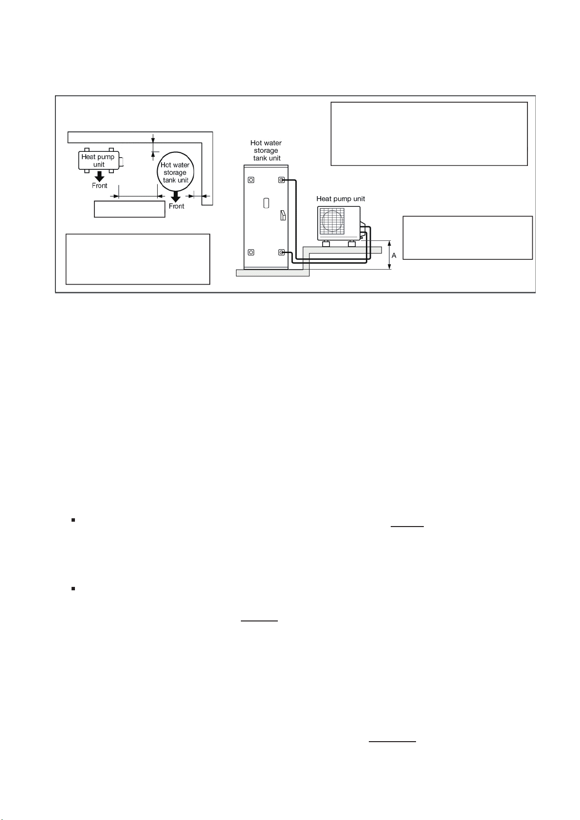
Figure 4: Restrictions on installation with the space between the tank unit and the
heat pump unit
Heat pump Unit Installation
The surface to which the heat pump unit is installed must be firm, preferably a
concrete pad or block. If the surface is firm there is no need to fix the unit to a base
surface, unless there is a likelihood of high wind or local vibration.
If the heat pump unit and tank unit are to fixed, appropriate fixing devices for the
weight/expected duty should be used. It is permissible to install the Heat Pump on
the side of a wall provide an adequate support is used.
Note: For California installation the Tank section water heater must be braced,
anchored, or strapped to avoid falling or moving during an earthquake. For Tank
size over 52 Gallons (236l) consult your local building jurisdiction for appropriate
bracing designs.
Note: For Florida installation the Heat Pump unit should be installed in accordance
with all local codes regarding Hurricane winds.
Use appropriately treated lumber or pre-fabricated “pump ups” to raise the Heat
Pump unit 4”-6” from the ground – this will allow defrost condensate to drain. In
areas with significant snowfall ensure unit is mounted above the anticipated
snowfall depth.
A Pressure Relief (PR) valve MUST be installed during the installation of the tank
unit. This is installed in a defined point near the top of the tank unit. The PR Valve
must have clear drainage where escaping steam or water can flow freely. PR Valve
setting should be 100 Psig.
The installation site must be well drained so that any water accumulating (such as
rain or pipe leakage) will drain away and not enter the heat pump unit and the tank
unit.
Supply water pressure must be a minimum of 29 PSI (200 kPa) to ensure Heat
Pump unit operation – If pressure is below 29 PSI install a booster pump to water
supply.
Caution
Keep the piping run to a minimum
as the longer the pipe run, the
greater the potential for heat loss
.
Side view
Overhead view
Standard layout
(A) Difference in height between
the base of tank and base of
Heat pump should be no more
than: 16ft(
5
m) Max.
>24” or 600mm
(Minimum Separation
Maximum pipe length
50
ft
(
15
m)
per
line between Tank & Heat Pump
Unit.
Maximum number of bends
–
6, use
long radius bends not street “L’s”
2”or
more
2”or
more
Sanden Heat Pump –Installation Manual
Page 6 of 40
Figure 4: Restrictions on installation with the space between the tank unit and the
heat pump unit
Heat pump Unit Installation
The surface to which the heat pump unit is installed must be firm, preferably a
concrete pad or block. If the surface is firm there is no need to fix the unit to a base
surface, unless there is a likelihood of high wind or local vibration.
If the heat pump unit and tank unit are to fixed, appropriate fixing devices for the
weight/expected duty should be used. It is permissible to install the Heat Pump on
the side of a wall provide an adequate support is used.
Note: For California installation the Tank section water heater must be braced,
anchored, or strapped to avoid falling or moving during an earthquake. For Tank
size over 52 Gallons (236l) consult your local building jurisdiction for appropriate
bracing designs.
Note: For Florida installation the Heat Pump unit should be installed in accordance
with all local codes regarding Hurricane winds.
Use appropriately treated lumber or pre-fabricated “pump ups” to raise the Heat
Pump unit 4”-6” from the ground – this will allow defrost condensate to drain. In
areas with significant snowfall ensure unit is mounted above the anticipated
snowfall depth.
A Pressure Relief (PR) valve MUST be installed during the installation of the tank
unit. This is installed in a defined point near the top of the tank unit. The PR Valve
must have clear drainage where escaping steam or water can flow freely. PR Valve
setting should be 100 Psig.
The installation site must be well drained so that any water accumulating (such as
rain or pipe leakage) will drain away and not enter the heat pump unit and the tank
unit.
Supply water pressure must be a minimum of 29 PSI (200 kPa) to ensure Heat
Pump unit operation – If pressure is below 29 PSI install a booster pump to water
supply.
Caution
Keep the piping run to a minimum
as the longer the pipe run, the
greater the potential for heat loss
.
Side view
Overhead view
Standard layout
(A) Difference in height between
the base of tank and base of
Heat pump should be no more
than: 16ft(
5
m) Max.
>24” or 600mm
(Minimum Separation
Maximum pipe length
50
ft
(
15
m)
per
line between Tank & Heat Pump
Unit.
Maximum number of bends
–
6, use
long radius bends not street “L’s”
2”or
more
2”or
more
3
6″(150mm)
or more
2″(50mm)
or more
24″(600mm) or more
Appropriately treated lumber or pre-fabricated “pump ups” MUST be used to raise
the Heat Pump unit 4”-6” from the ground – this will allow defrost condensate to
drain. In areas with signicant snowfall ensure unit is mounted above the anticipated
snowfall depth.
Wall Brackets and other mounting solutions are also available from ECO2 Systems LLC
.
Sanden Heat Pump –Installation Manual
Page 6 of 40
Figure 4: Restrictions on installation with the space between the tank unit and the
heat pump unit
Heat pump Unit Installation
The surface to which the heat pump unit is installed must be firm, preferably a
concrete pad or block. If the surface is firm there is no need to fix the unit to a base
surface, unless there is a likelihood of high wind or local vibration.
If the heat pump unit and tank unit are to fixed, appropriate fixing devices for the
weight/expected duty should be used. It is permissible to install the Heat Pump on
the side of a wall provide an adequate support is used.
Note: For California installation the Tank section water heater must be braced,
anchored, or strapped to avoid falling or moving during an earthquake. For Tank
size over 52 Gallons (236l) consult your local building jurisdiction for appropriate
bracing designs.
Note: For Florida installation the Heat Pump unit should be installed in accordance
with all local codes regarding Hurricane winds.
Use appropriately treated lumber or pre-fabricated “pump ups” to raise the Heat
Pump unit 4”-6” from the ground – this will allow defrost condensate to drain. In
areas with significant snowfall ensure unit is mounted above the anticipated
snowfall depth.
A Pressure Relief (PR) valve MUST be installed during the installation of the tank
unit. This is installed in a defined point near the top of the tank unit. The PR Valve
must have clear drainage where escaping steam or water can flow freely. PR Valve
setting should be 100 Psig.
The installation site must be well drained so that any water accumulating (such as
rain or pipe leakage) will drain away and not enter the heat pump unit and the tank
unit.
Supply water pressure must be a minimum of 29 PSI (200 kPa) to ensure Heat
Pump unit operation – If pressure is below 29 PSI install a booster pump to water
supply.
Caution
Keep the piping run to a minimum
as the longer the pipe run, the
greater the potential for heat loss
.
Side view
Overhead view
Standard layout
(A) Difference in height between
the base of tank and base of
Heat pump should be no more
than: 16ft(
5
m) Max.
>24” or 600mm
(Minimum Separation
Maximum pipe length
50
ft
(
15
m)
per
line between Tank & Heat Pump
Unit.
Maximum number of bends
–
6, use
long radius bends not street “L’s”
2”or
more
2”or
more
125
Heat Pump Unit Installation
66ft(20m)
23ft(7m)
bottom of
SANCO2Heat Pump – Installation Manual
Page 7 of 44
Sanden Heat Pump –Installation Manual
Page 7 of 40
Note:
The entire system is set up and fully functional when supplied. Once all the water and
electric connections have been made, the system will operate automatically provided that
mains power is available.
The only adjustments to the unit are to set the desired hot water supply temperature & set
the current time on the operation panel under the top housing cover, especially if the block
out time setting is desired. See Set point adjustment, current time setting, and block out
time section on page 19.
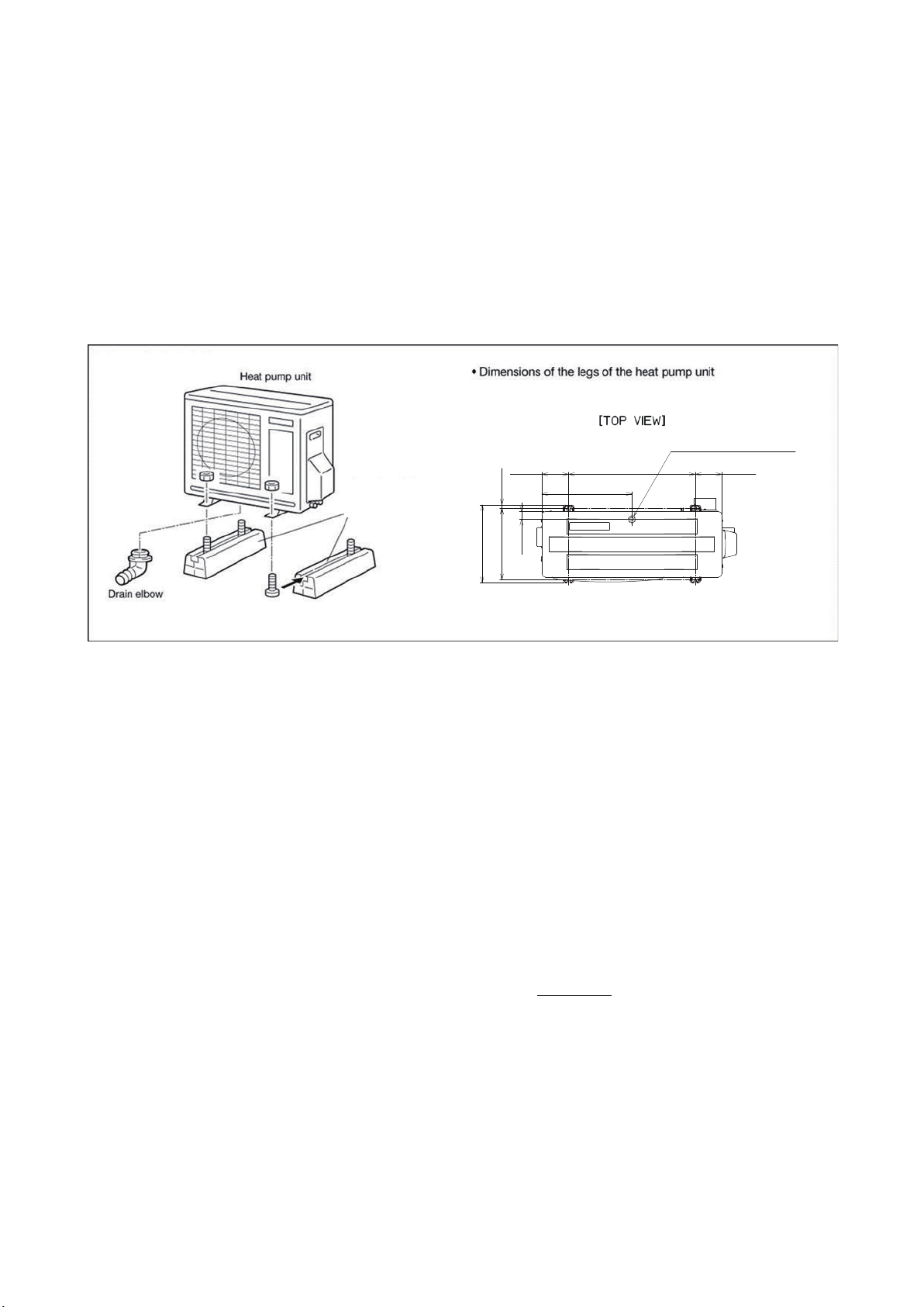
Figure 5: Heat pump installation example and dimensions
Attach the drain elbow to the drain opening located on the bottom of the heat pump
unit. The drain elbow is included in the installation kit for the heat pump unit.
Attach a drain hose with 5/8 inch (16mm) of inner diameter to the drain elbow to guide
the drained water to an appropriate drain.
Water Piping Installation – Heat Pump Unit & Tank
All piping that connects to the water supply must be installed by a licensed contractor.
The water supplied to the system must comply with the potable water quality standard.
Use of water that does not comply with this standard could result in a malfunction of
the system.
Description
PH
TDS
(Total
Dissolved
Solids)
Total
Hardness
(calcium Ion
concentration)
Aluminium
Chlorides
Copper
Iron
Manganese
Zinc
Maximum
Levels
6.0
to
9.0
Up to
500 ppm
Up to
200ppm or
12 grains
hardness
Up to
0.2 ppm
Up to
200
ppm
Up to
1.0
ppm
Up
to
0.3
ppm
Up to
0.05 ppm
Up
to 5
ppm
The water supply must have a pressure of 29 PSI (200 kPa) or higher.
A drain trap must be installed on the drain pipe if water is to be drained to a drain pan.
Unit Weight
106lbs
(㼀㻻㻼㻌㼂㻵㻱㼃)
4
108lbs
Sanden Heat Pump –Installation Manual
Page 7 of 40
Note:
The entire system is set up and fully functional when supplied. Once all the water and
electric connections have been made, the system will operate automatically provided that
mains power is available.
The only adjustments to the unit are to set the desired hot water supply temperature & set
the current time on the operation panel under the top housing cover, especially if the block
out time setting is desired. See Set point adjustment, current time setting, and block out
time section on page 19.
Figure 5: Heat pump installation example and dimensions
Attach the drain elbow to the drain opening located on the bottom of the heat pump
unit. The drain elbow is included in the installation kit for the heat pump unit.
Attach a drain hose with 5/8 inch (16mm) of inner diameter to the drain elbow to guide
the drained water to an appropriate drain.
Water Piping Installation – Heat Pump Unit & Tank
All piping that connects to the water supply must be installed by a licensed contractor.
The water supplied to the system must comply with the potable water quality standard.
Use of water that does not comply with this standard could result in a malfunction of
the system.
Description
PH
TDS
(Total
Dissolved
Solids)
Total
Hardness
(calcium Ion
concentration)
Aluminium
Chlorides
Copper
Iron
Manganese
Zinc
Maximum
Levels
6.0
to
9.0
Up to
500 ppm
Up to
200ppm or
12 grains
hardness
Up to
0.2 ppm
Up to
200
ppm
Up to
1.0
ppm
Up
to
0.3
ppm
Up to
0.05 ppm
Up
to 5
ppm
The water supply must have a pressure of 29 PSI (200 kPa) or higher.
A drain trap must be installed on the drain pipe if water is to be drained to a drain pan.
Unit Weight
106lbs
(㼀㻻㻼㻌㼂㻵㻱㼃)
4.82"22.83"
4.82"
16.24"
14.02"
0.59"12.88"
1.41"
DRAIN CONNECTOR
Unit:inch
top housing cover & especially if the block out time setting is desired.
set the current time on the operation panel under the
Sanden Heat Pump –Installation Manual
Page 6 of 40
Figure 4: Restrictions on installation with the space between the tank unit and the
heat pump unit
Heat pump Unit Installation
The surface to which the heat pump unit is installed must be firm, preferably a
concrete pad or block. If the surface is firm there is no need to fix the unit to a base
surface, unless there is a likelihood of high wind or local vibration.
If the heat pump unit and tank unit are to fixed, appropriate fixing devices for the
weight/expected duty should be used. It is permissible to install the Heat Pump on
the side of a wall provide an adequate support is used.
Note: For California installation the Tank section water heater must be braced,
anchored, or strapped to avoid falling or moving during an earthquake. For Tank
size over 52 Gallons (236l) consult your local building jurisdiction for appropriate
bracing designs.
Note: For Florida installation the Heat Pump unit should be installed in accordance
with all local codes regarding Hurricane winds.
Use appropriately treated lumber or pre-fabricated “pump ups” to raise the Heat
Pump unit 4”-6” from the ground – this will allow defrost condensate to drain. In
areas with significant snowfall ensure unit is mounted above the anticipated
snowfall depth.
A Pressure Relief (PR) valve MUST be installed during the installation of the tank
unit. This is installed in a defined point near the top of the tank unit. The PR Valve
must have clear drainage where escaping steam or water can flow freely. PR Valve
setting should be 100 Psig.
The installation site must be well drained so that any water accumulating (such as
rain or pipe leakage) will drain away and not enter the heat pump unit and the tank
unit.
Supply water pressure must be a minimum of 29 PSI (200 kPa) to ensure Heat
Pump unit operation – If pressure is below 29 PSI install a booster pump to water
supply.
Caution
Keep the piping run to a minimum
as the longer the pipe run, the
greater the potential for heat loss
.
Side view
Overhead view
Standard layout
(A) Difference in height between
the base of tank and base of
Heat pump should be no more
than: 16ft(
5
m) Max.
>24” or 600mm
(Minimum Separation
Maximum pipe length
50
ft
(
15
m)
per
line between Tank & Heat Pump
Unit.
Maximum number of bends
–
6, use
long radius bends not street “L’s”
2”or
more
2”or
more

SANCO2Heat Pump – Installation Manual
Page 8 of 44
Sanden Heat Pump –Installation Manual
Page 8 of 40
This product cannot be connected to a solar water heater.
The piping must be insulated with MINIMUM ¾” to 1” closed cell insulation.
Self Regulating Heat tape (3-5W per foot) must be installed on both Water Lines to the
Heat Pump to protect the water piping in areas with design temperatures below 27°F.
If the piping needs brazing, make sure that all flux and flux splatter is wiped away with
a wet cloth. When brazing, ensure connections are protected using a wet cloth.
As the hot-water supply pipe will expand and contract, use sleeves when penetrating
through concrete walls or slabs.
With buried piping, an outer cover will need to be used that has had both ends sealed
to avoid any ingress of rain.
Use only heat-resistant and corrosive-resistant material to seal the pipe joints.
Cutting and wrenching the piping material may result in oil and dust adhering to it. After
processing, clean the material with a mild detergent before doing any piping work and
smooth the edges to remove any scratches and burrs. (After flowing water through it
verify whether any debris has accumulated on the filter of the faucet and heat pump
unit pipe.)
When using PTFE sealing tape, ensure that no tape is sticking out of the threads.
Any heat-resistant PVC piping use is NOT recommended due to high outlet water
temperature for between the heat pump and the tank as well as the tank and the
mixing valve.
Follow the manufacturer’s instruction manual for the type of bond, amount to be
applied, curing time, and other specifications.
If any bond or flux has entered the tank unit and the hot water has a chemical/acrid
smell, take the following countermeasures.
a) After heating the water in the tank unit, drain it and clean inside the tank unit. Fill
the tank unit with 26 gallons (100 litres) of water and exchange twice.
b) Clean or change the filter.
c) Fill up the tank unit.
d) Drain water from the relief valve for one to two minutes.
e) Run water from all the hot water supply faucets in the house for about ten minutes
to clean inside the pipes.
5-8W

SANCO2Heat Pump – Installation Manual
Page 9 of 44
Bleed the air from the system according to the instructions below on Page 17.
Make sure all the necessary devices are mounted to the pipes as shown in diagram.
If the heat pump unit piping is kinked or clogged or the air inside was not bled during
the test operation, temperature of the supplied hot water may become inconsistent.
Sanden Heat Pump –Installation Manual
Page 8 of 40
This product cannot be connected to a solar water heater.
The piping must be insulated with MINIMUM ¾” to 1” closed cell insulation.
Self Regulating Heat tape (3-5W per foot) must be installed on both Water Lines to the
Heat Pump to protect the water piping in areas with design temperatures below 27°F.
If the piping needs brazing, make sure that all flux and flux splatter is wiped away with
a wet cloth. When brazing, ensure connections are protected using a wet cloth.
As the hot-water supply pipe will expand and contract, use sleeves when penetrating
through concrete walls or slabs.
With buried piping, an outer cover will need to be used that has had both ends sealed
to avoid any ingress of rain.
Use only heat-resistant and corrosive-resistant material to seal the pipe joints.
Cutting and wrenching the piping material may result in oil and dust adhering to it. After
processing, clean the material with a mild detergent before doing any piping work and
smooth the edges to remove any scratches and burrs. (After flowing water through it
verify whether any debris has accumulated on the filter of the faucet and heat pump
unit pipe.)
When using PTFE sealing tape, ensure that no tape is sticking out of the threads.
Any heat-resistant PVC piping use is NOT recommended due to high outlet water
temperature for between the heat pump and the tank as well as the tank and the
mixing valve.
Follow the manufacturer’s instruction manual for the type of bond, amount to be
applied, curing time, and other specifications.
If any bond or flux has entered the tank unit and the hot water has a chemical/acrid
smell, take the following countermeasures.
a) After heating the water in the tank unit, drain it and clean inside the tank unit. Fill
the tank unit with 26 gallons (100 litres) of water and exchange twice.
b) Clean or change the filter.
c) Fill up the tank unit.
d) Drain water from the relief valve for one to two minutes.
e) Run water from all the hot water supply faucets in the house for about ten minutes
to clean inside the pipes.
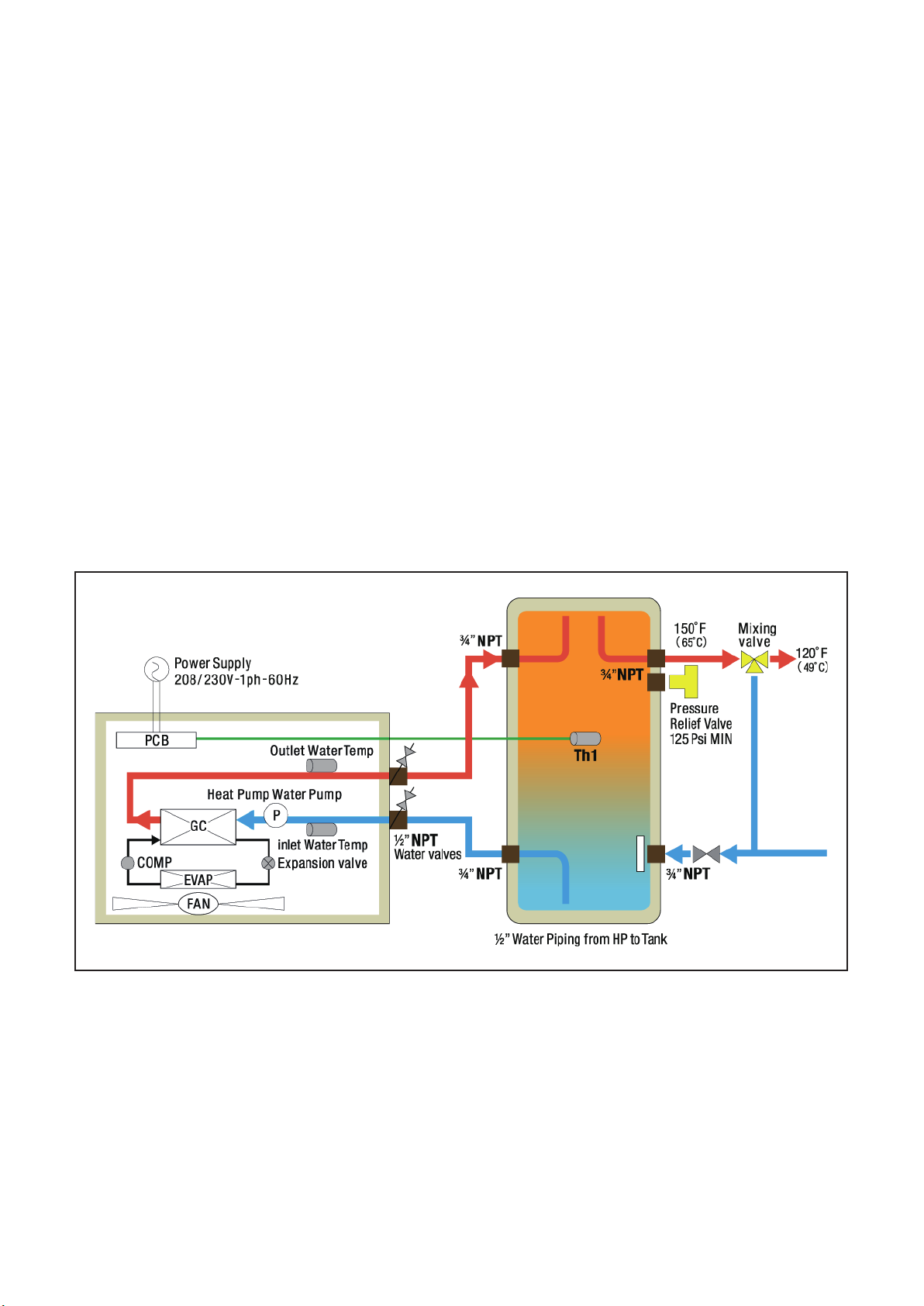
Figure 5: Reguired System piping (Typical System piping)
Sanden Heat Pump –Installation Manual
Page 9 of 40
Heat Pump Unit Water piping
ALL PIPING BETWEEN HEAT PUMP & TANK SHOULD BE ½” NO EXCEPTIONS
Connect the heat pump unit COLD supply to the tank unit fitting marked Cold Supply. –
½” NPT Connection (Certain early units may use ½” BSP connections).
Connect the heat pump unit HOT return to the tank unit fitting marked Hot Return – ½”
NPT Connection (Certain early units may use ½” BSP connections).
Connect the mains water supply to the lower fitting on the tank unit marked Cold Water
Inlet.
Connect the hot water supply pipe to the top of the tank unit marked Hot Water Outlet.
Install the PR valve to the fitting on the tank unit marked PR valve, pipe from PR valve
directly to a Building drain; do not install any shut off valve between PR valve and
Building drain.
Run water through the pipe(s) to remove any debris inside before connecting the
pipe(s).
After all the piping connections are completed, run water through the system.
Remove the air from the system according to the instructions below on Page 15.
Make sure all the necessary devices are mounted to the pipes as shown in diagram.
If the heat pump unit piping is kinked or clogged or the air inside was not removed
during the test operation, temperature of the supplied hot water may become
inconsistent.
Figure 6: System piping (Typical System piping)
Piping
WATER
. (Use 1/2” BSP
to 1/2” NPT connection adapter.)
. (Use 1/2” BSP
to 1/2” NPT connection adapter.)
HOT WATER
1/2"
1/2"
Notes :
Isolation Valves shown in typical positions
Union type connections and Isolation valves
recommended for ease of installation and service
Condensate drain line from base of Heat Pump
not shown, pipe to drain or other location in
1/2"
accordance with local codes
Tank Temperature sensor connecting Tank
to Heat Pump not shown
Piping between Tank and Heat Pump
66ft Maximum length, 23ft Maximum vertical separation
To/from bottom of Tank to bottom of Heat Pump
No more than 6 x Elbows/Bends
Insulate ALL piping external to the building
with minimum 3/4" Closed Cell insulation
Check coldest expected ambient temperature
to determine if Trace Heat Kit FG2-6L is required 1/2"
ECO-FPVKT3540 Power Outage kit also available
Cold Water Inlet should be regulated to below 95 Psi
Cold Water Inlet from Building
Title : SANCO2 Heat Pump unit & Storage Tank Standard Installation
Drg # :ECO2-GSHP-001 Drawn : JLM Rev : 01 Reissue 10/2020
©2020 Eco2 Systems LLC
11/19/2019
HEAT
PUMP
Hot Out
HEAT
PUMP
Cold In
GS4-45HPC HEAT PUMP
DHW STORAGE
TANK
COLD
TANK
to HP
HOT
HP to
TANK
DHW
COLD
IN
DHW
HOT
OUT
PRV
PIPE to
DRAIN
Mixed Outlet to
Building/Home
Cold Water
to Anti Scald
Valve
Hot Water
to Anti Scald
Valve
Anti Scald
Valve -
Supplied with
System

SANCO2Heat Pump – Installation Manual
Page 10 of 44
How to Connect Main Power
Remove the power box cover (Philips head screwdriver required).
Connect the power wiring to the terminal block per the wiring diagram/manual.
Ensure ground wire is connected.
Secure the eld power supply wiring below the terminal block with the screw
clamp tting.
Re attach the power box cover to the heat pump unit.
Sanden Heat Pump –Installation Manual
Page 10 of 40
Mains Power/Electrical Installation
All Electrical Wiring should be done in accordance with the latest edition of the
National Electrical Code (NEC) and all local State/Province and Municipality codes.
The power requirement for the system is a dedicated 15 amp circuit fitted with a
circuit breaker. This circuit may be connected to constant power or off-peak power.
A local disconnect should be installed adjacent to the Heat Pump unit in
accordance to NEC and local codes.
Installation of this system must be carried out only by a qualified installation
technician (electrical, HVAC or plumbing).
Electrical connections
Breaker size and wiring must be sized per NEC rules for the rating plate amperage,
MCA and MOP or Max Circuit Breaker.
Power Supply is 208/230V-1Ph-60Hz
Verify that the tank unit is full of water and the
water shut off valves are open before turning on the
power.
How to connect Main Power
Remove the terminal block cover (Philips head screwdriver required)
Connect the power wiring to the terminal block per the wiring diagram/manual.
Ensure ground wire is connected.
Secure the field power supply wiring below the terminal block with the screw clamp
fitting.
Re attach the terminal block cover to the heat pump unit.
Electrical Connections
SANCO2Heat Pump – Installation Manual
Page 11 of 44
Figure 6:Main Power Connection
0.5mm〜1mm
Power wire
Core
Heat Pump 208/230V Power Wiring must use solid copper wire.
Appropriately sized ring or fork terminals are recommended for easier connection.
Power supply
208/230V
Black
Wihte
Green/Yellow
Power line
Ground
5×M4 Screws
Wire holder band
Sanden Heat Pump –Installation Manual
Page 10 of 40
Mains Power/Electrical Installation
All Electrical Wiring should be done in accordance with the latest edition of the
National Electrical Code (NEC) and all local State/Province and Municipality codes.
The power requirement for the system is a dedicated 15 amp circuit fitted with a
circuit breaker. This circuit may be connected to constant power or off-peak power.
A local disconnect should be installed adjacent to the Heat Pump unit in
accordance to NEC and local codes.
Installation of this system must be carried out only by a qualified installation
technician (electrical, HVAC or plumbing).
Electrical connections
Breaker size and wiring must be sized per NEC rules for the rating plate amperage,
MCA and MOP or Max Circuit Breaker.
Power Supply is 208/230V-1Ph-60Hz
Verify that the tank unit is full of water and the
water shut off valves are open before turning on the
power.
How to connect Main Power
Remove the terminal block cover (Philips head screwdriver required)
Connect the power wiring to the terminal block per the wiring diagram/manual.
Ensure ground wire is connected.
Secure the field power supply wiring below the terminal block with the screw clamp
fitting.
Re attach the terminal block cover to the heat pump unit.

SANCO2Heat Pump – Installation Manual
Page 12 of 44
Sanden Heat Pump –Installation Manual
Page 12 of 40
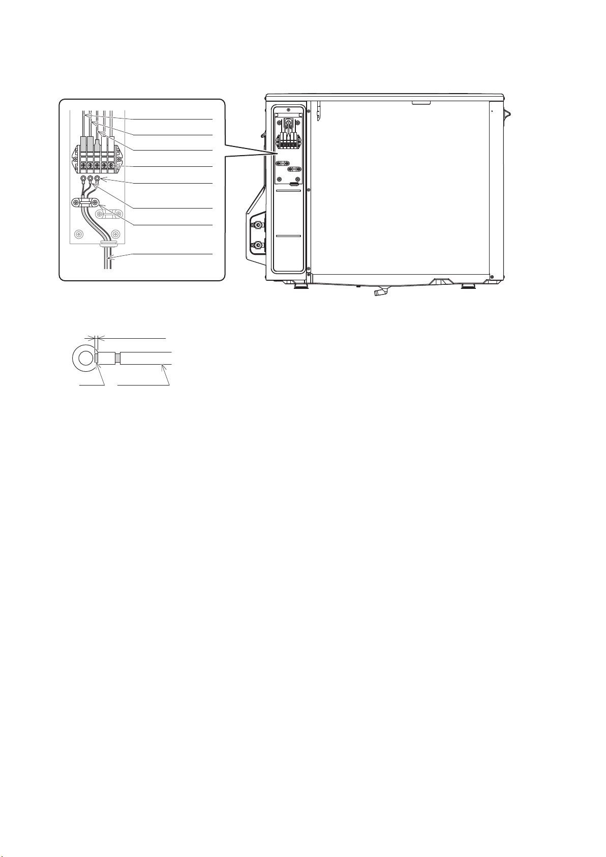
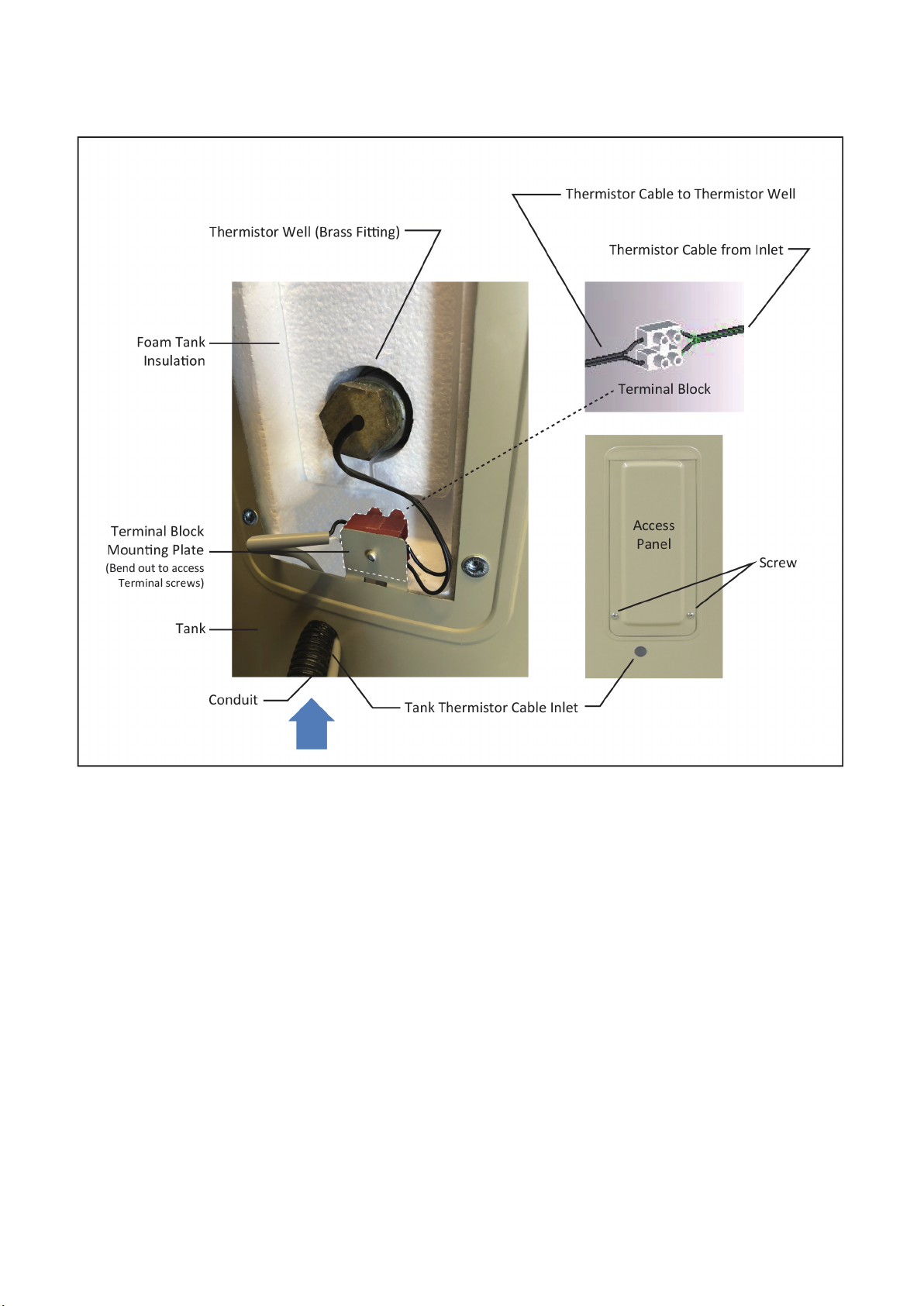
How to connect Tank thermistor cable to Heat Pump unit
The thermistor cable and conduit length are provided to cover 16.5 feet between the
tank and the Heat Pump.
If the units are located closer, the thermistor cable and conduit may be cut to the
desired length (Figure 8).
If the units are further apart, the thermistor cable may be extended by connecting an
18-2 AWG Shielded wire to the existing thermistor cable – connections are not
polarity sensitive.
Attach the conduit connector to the conduit end. Push the conduit into the opening on
the connector until the conduit does not go any further. Pull the conduit several times
to ensure the connector is fixed properly to the conduit.
Unscrew and carefully remove the terminal block cover on the tank. Do not use
unnecessary force to remove the cover as this could pull and break the cable coming
out of the tank unit.
Attach the connector on the end of the thermistor conduit coming from the heat pump
unit side to the opening on the bottom of the cover on the tank unit.
Confirm the gasket is adhered to the thread of the conduit connector before attaching
the connector to the cover. If the gasket is not present, there is a risk of water getting
inside the cover and this may result in a malfunction of the terminal block.
Connect the thermistor cables to the bottom of the terminal block.
Replace the terminal block cover back onto the tank unit and tighten the screws.
Note :
SAN-119GLBK tank does not include an access panel / terminal block.
7
How to Connect Tank Thermistor Cable to Heat Pump Unit
SANCO2Heat Pump – Installation Manual
Page 13 of 44
Sanden Heat Pump –Installation Manual
Page 12 of 40
How to connect Tank thermistor cable to Heat Pump unit
The thermistor cable and conduit length are provided to cover 16.5 feet between the
tank and the Heat Pump.
If the units are located closer, the thermistor cable and conduit may be cut to the
desired length (Figure 8).
If the units are further apart, the thermistor cable may be extended by connecting an
18-2 AWG Shielded wire to the existing thermistor cable – connections are not
polarity sensitive.
Attach the conduit connector to the conduit end. Push the conduit into the opening on
the connector until the conduit does not go any further. Pull the conduit several times
to ensure the connector is fixed properly to the conduit.
Unscrew and carefully remove the terminal block cover on the tank. Do not use
unnecessary force to remove the cover as this could pull and break the cable coming
out of the tank unit.
Attach the connector on the end of the thermistor conduit coming from the heat pump
unit side to the opening on the bottom of the cover on the tank unit.
Confirm the gasket is adhered to the thread of the conduit connector before attaching
the connector to the cover. If the gasket is not present, there is a risk of water getting
inside the cover and this may result in a malfunction of the terminal block.
Connect the thermistor cables to the bottom of the terminal block.
Replace the terminal block cover back onto the tank unit and tighten the screws.
Note :
SAN-119GLBK tank does not include an access panel / terminal block.
Figure 7: Connecting tank unit thermistor cable - SAN Tanks shown as example
SANCO2Heat Pump – Installation Manual
Page 14 of 44
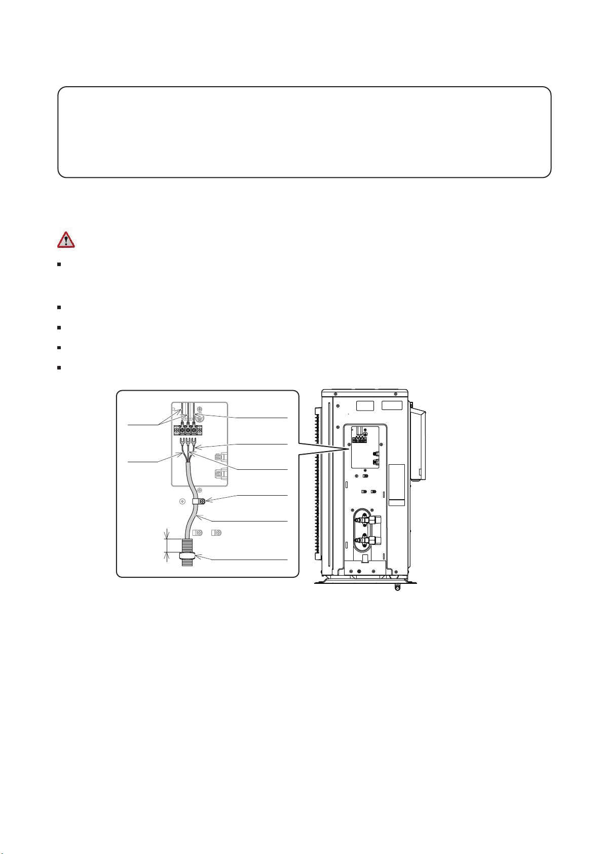
Electrical Installation
Please note:
All Electrical Wiring should be done in accordance with the latest
edition of the National Electrical Code (NEC) and all local State/
Province and Municipality codes.
Remove the piping cover.
Connect the thermistor cable line to the terminal block.
Installation of this system must be carried out only by a qualied installation
technican (electrical, HVAC or plumbing).
Fix the thermistor cable with the code clip and conduit clip.
Attach the piping cover back on the heat pump unit.
Conduit clip
Code clip
Thermistor cable
Wihte
Green
Green
Blue
Black
25mm
or
less
Figure 8:Connecting Heat Pump unit thermistor cable
Sanden Heat Pump –Owner’s Manual
Page 7 of 24
Installation details
This Sanden Eco Hot water Heat Pump System must be installed by licensed personnel in
accordance with local building codes:
Installing contractor should be licensed by applicable state/province and municipal
authorities to install an Electrical & Plumbing product.
The unit has been designed for heating potable domestic hot water and any other
usage, such as space heating requires a heat exchanger suitable for local codes to
be installed on the system to separate potable and non-potable water.
The unit is designed to operate when connected to the water supply with a
maximum operating pressure of 95PSI (655 kPa). To ensure the mains pressure
does not exceed this, first check incoming cold water mains pressure, and then a
pressure regulating device must be connected to the water supply line.
This system delivers hot water exceeding 120 oF (50 oC).
Installation of a temperature tempering device is MANDATORY to avoid potential
scalds and burns.
The unit must be stored and transported in an upright position. Failure to do so may
render the unit faulty. Such failure is not covered under any warranty agreements.
Failure to comply with the above conditions will void the warranty.
DANGER
SANCO2Heat Pump – Installation Manual
Page 15 of 44
Sanden Heat Pump –Installation Manual
Page 14 of 40
If the unit is connected to Demand Response power and hot water consumption has
been higher than normal, hot water might not be available until the next power
supply cycle.
Daily frequency and amount of hot water consumption may also affect the duration
of the heating cycle operation.
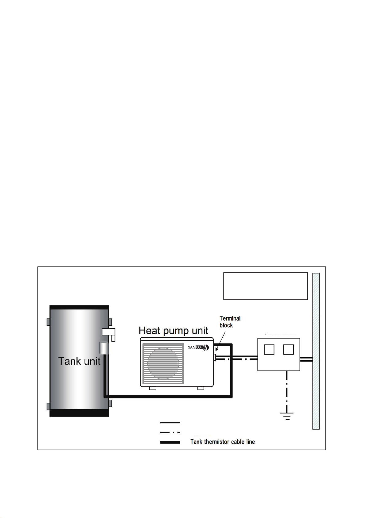
Figure 9: Outline of electrical system connections
The basic system installation is now complete; the unit is
now ready for initial water filling, air purge and then start up
Check the Installation against the Installation Check list
provided at the end of this manual
Ensure that the work site is tidy; Sanden International recommends the use of Slim Duct or
Fortress product to cover water piping on the outside of the house.
Caution
Use copper wiring
208/230V Power
Ground Wire
Breaker Box
Sanden Heat Pump –Installation Manual
Page 14 of 40
If the unit is connected to Demand Response power and hot water consumption has
been higher than normal, hot water might not be available until the next power
supply cycle.
Daily frequency and amount of hot water consumption may also affect the duration
of the heating cycle operation.
Figure 9: Outline of electrical system connections
The basic system installation is now complete; the unit is
now ready for initial water filling, air purge and then start up
Check the Installation against the Installation Check list
provided at the end of this manual
Ensure that the work site is tidy; Sanden International recommends the use of Slim Duct or
Fortress product to cover water piping on the outside of the house.
Caution
Use copper wiring
208/230V Power
Ground Wire
Breaker Box
Sanden Heat Pump –Installation Manual
Page 13 of 40
Figure 8: Connecting tank unit thermistor cable – GAUS Tanks shown as example
System operation using continuous Power Supply
If the block out time function is selected (setting is covered on Page 18) the unit will
not operate during the block out times – this function is typically used on
installations that have time of use electricity tariffs.
The water heating cycle operation starts automatically when the residual hot water
in the tank unit is less than 40 gallons (150 litres).
The system will not run if the electrical power supply is cut off. However, the system
will automatically start operation, once the electric power supply is restored.
System operation if connected to Demand Response Power
There are no special settings for the Demand Response. The system will run once
power becomes available and the temperature in the tank drops below the set point
of the tank thermistor.
If connecting the unit to Demand Response power ensure that the power supply
provides a minimum of 5 hours continuous power, as it can take at least four hours
to fill the tank unit with hot water.
If the ambient temperature is lower than 50oF (10oC) this can be longer.
Thermistor
cable
Gasket
Conduit
connector
Conduit
Terminal
block
Tank unit
Screw
22
System Operation If Connected to Dry Contact
Dry Contact input. The system will run once dry
power supply is cut off. However, the system will
automatically start operation, once the electric power supply is restored.
contact input is closed and the temperature in the tank drops below the set point of
the tank thermistor.
Dry Contact and hot water consumption has been higher
than normal, hot water might not be available until the next power supply cycle.
Standard System Operation
23
SANCO2Heat Pump – Installation Manual
Page 16 of 44
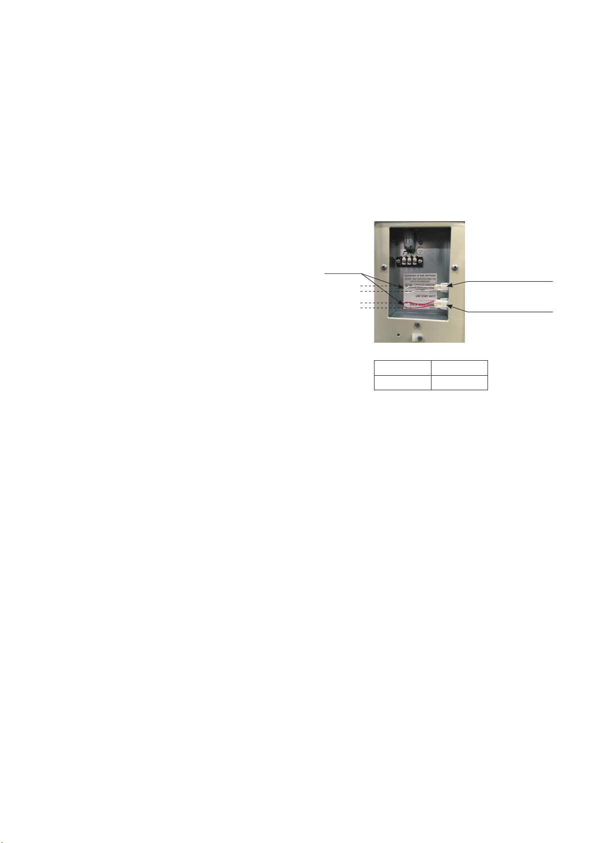
How to Connect Dry Contact
Dry Contact Purpose
・
UNIT START INPUT
Allow External ON/OFF switching of the Heat Pump –
Commonly used in Utility programs or other installations where having control of the Heat
Pump other than Tank temperature is required.
Note: Even should the unit be in the OFF mode via the Dry Contact the Freeze Protection
program may still start the unit depending on Ambient and Water temperatures.
・
ERROR SIGNAL OUTPUT
Send an error to Utility programs.
Installation of Dry Contact switching
Remove the pipe cover.
Locate the Dry Contact loop.
Cut the loop and strip wire from the two ends.
Wire to external utility, note the maximum
voltage and current requirements.
CAUTION : If voltage is applied to the Dry contact terminal from the outside switch, the
equipment will be damaged.
Unit Operation
・
UNIT START INPUT
When the switch is in the OPEN position the unit is OFF
(Exception – Unit will run if Freeze protection mode is activated)
When the switch is in the CLOSED position the unit is ON
The unit will now be controlled by the Tank Temperature Thermistor
Unit will run if the Tank temperature is below 113°F as sensed by the thermistor
・
ERROR SIGNAL OUTPUT
When an error has occurred, the switch is open.
UNIT START INPUT
Cut
ERROR SIGNAL
OUTPUT
To Utility
Contact specication
Voltage 5V
Current 2mA
Sanden Heat Pump –Installation Manual
Page 14 of 40
If the unit is connected to Demand Response power and hot water consumption has
been higher than normal, hot water might not be available until the next power
supply cycle.
Daily frequency and amount of hot water consumption may also affect the duration
of the heating cycle operation.
Figure 9: Outline of electrical system connections
The basic system installation is now complete; the unit is
now ready for initial water filling, air purge and then start up
Check the Installation against the Installation Check list
provided at the end of this manual
Ensure that the work site is tidy; Sanden International recommends the use of Slim Duct or
Fortress product to cover water piping on the outside of the house.
Caution
Use copper wiring
208/230V Power
Ground Wire
Breaker Box
SANCO2
The basic system installation is now complete; the unit is
now ready for initial water lling, bleeding and then start up
Check the Installation against the Installation Check list
provided at the end of this manual

SANCO2Heat Pump – Installation Manual
Page 17 of 44
Filling the System & Bleeding Air
The following steps must be taken to ensure all air is bled from the system.
Incorrect bleeding of air may cause the water temperature to vary during operation, and
lead to possible error codes.
・
Ensure that all piping to tank unit and heat pump unit are installed and connections are
tight, then open the Cold Water Supply Valve to the system.
・
Push up the lever on the PR valve to open, and ll the tank unit with water.
Conrm that water comes out of the relief valve, and then close the lever.
・
Open the hot water faucets to bleed air from the house piping system.
・
Close the faucets after no air is seen in the water.
・
Open the water drain plug on the heat pump unit.
Close the plugs after no air is seen in the water or a steady stream of water is present.
・
Supply power to the heat pump unit.
・
Display shows "1200" then "Clock setting mode" is started with operating "Air bleeding
process" at the same time.
・
In case nish time setting or nothing is operated for 1 minute, "Clock setting mode" is
terminated and "APon" will be displayed on the monitor.
・
"Air bleeding process" will be done in 5 minutes.
Once it's nished, current time will be shown on monitor.
・
Leave the hot water faucets open for 3 minutes.
Close the faucets after no air can be seen in the water.
Sanden Heat Pump – Owner’s Manual
Page 11 of 20
Removing air from the system
Please note:
Plumbing work should only be completed by a licensed plumber
• The following steps must be taken to ensure all air is removed from the system.
Incorrect removal of air may cause the water temperature to vary.
• Plumb pipes to the tank unit and the heat pump unit.
• Push up the lever on the PTR valve to open, and fill the tank unit with water.
• Confirm that the water comes out of the relief valve and then close the lever.
• Open the hot water taps in the home to remove air.
• Close the hot water taps in the home after no air is confirmed in the water.
• Open the water drain plug on the heat pump unit.
• Close the plug after no air is confirmed in the water.
• Connect the power to the heat pump unit.
• Air removing process (Refer to figure 4)
1. Switching to Air Removing Mode
Long press the “Up” and “Down” keys to switch to the “Heat Setting Mode”.
2. Press the “Up” or “Down” keys to switch to the “Air Removing Mode” and press
the “Enter” key. Press the “Up” keys again to display “APon”, then press the
“Enter” key.
After 5 minutes, the air removing mode will automatically finish and the display will
show [Air ] again.
• Open the hot water taps in the home to remove air.
• Close the hot water taps in the home after no air is confirmed in the water.
*Caution
If air removing mode is not completed, the system will not start the heating cycle.
Figure 4: Air removing process
PR valve lever
PR valve to open,
Figure 10: Air bleeding process
Sanden Heat Pump –Installation Manual
Page 14 of 40
If the unit is connected to Demand Response power and hot water consumption has
been higher than normal, hot water might not be available until the next power
supply cycle.
Daily frequency and amount of hot water consumption may also affect the duration
of the heating cycle operation.
Figure 9: Outline of electrical system connections
The basic system installation is now complete; the unit is
now ready for initial water filling, air purge and then start up
Check the Installation against the Installation Check list
provided at the end of this manual
Ensure that the work site is tidy; Sanden International recommends the use of Slim Duct or
Fortress product to cover water piping on the outside of the house.
Caution
Use copper wiring
208/230V Power
Ground Wire
Breaker Box
CAUTION : Air bleeding valve is located at the bottom of the heat pump unit!
Open
The air bleeding valve
Open the faucet to bleed air. Close the faucet
after no air bubbles can be seen in the water.
Open the air bleeding valve on the Heat Pump
Unit.
Close the valve after no air is conrmed in the
water supply.
Then connect power to the Heat Pump Unit.
Open faucet.

SANCO2Heat Pump – Installation Manual
Page 18 of 44
Sanden Heat Pump –Installation Manual
Page 16 of 40
Freeze protection
Even if the water pipes have been insulated, the piping can freeze if the
surrounding temperature falls below freezing (32oF). This could cause damage to
the equipment and piping so make sure the appropriate freeze protection measures
are taken.
Follow the instructions in the installation manual provided with the freeze protection
heat tape.
After completion of the piping, inspect the plumbing for any water leaks from the
joints before installing freeze protection.
Wrap the freeze protection heater around the pipes, up to the water connectors of
the Heat Pump unit.
Ensure the freeze protection heaters are connected to a 24 hours continuous
power supply.
It is important to fully explain the use and operation of the freeze protection heater
to the customer.
When turning off the power, because the unit will not be in use, ALL water
must be drained from the unit and piping.
Note: Heat tape that uses the outside temperature to energize, may not maintain
the temperature of the pipes correctly. It is important to use a heat tape that
directly senses the pipe’s temperature.
Figure 11: Details on wrapping thermal insulation around the piping connector
Heater
Insulation
Tapes
Thermal
Insulation
Band
Pipe wrapping Connection wrapping
Freeze protection valves can be installed for freeze protection during power outage.
Freeze Protection
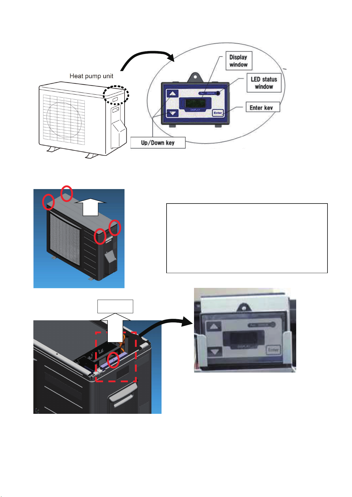
SANCO2Heat Pump – Installation Manual
Page 19 of 44
Sanden Heat Pump –Installation Manual
Page 16 of 40
Freeze protection
Even if the water pipes have been insulated, the piping can freeze if the
surrounding temperature falls below freezing (32oF). This could cause damage to
the equipment and piping so make sure the appropriate freeze protection measures
are taken.
Follow the instructions in the installation manual provided with the freeze protection
heat tape.
After completion of the piping, inspect the plumbing for any water leaks from the
joints before installing freeze protection.
Wrap the freeze protection heater around the pipes, up to the water connectors of
the Heat Pump unit.
Ensure the freeze protection heaters are connected to a 24 hours continuous
power supply.
It is important to fully explain the use and operation of the freeze protection heater
to the customer.
When turning off the power, because the unit will not be in use, ALL water
must be drained from the unit and piping.
Note: Heat tape that uses the outside temperature to energize, may not maintain
the temperature of the pipes correctly. It is important to use a heat tape that
directly senses the pipe’s temperature.
Figure 11: Details on wrapping thermal insulation around the piping connector
Heater
Insulation
Tapes
Thermal
Insulation
Band
Pipe wrapping Connection wrapping
Sanden Heat Pump – Installation Manual
Page 15 of 32
Figure 12 How to operate the controller
How to remove the operation panel
1.Remove Top Panel (4 screws)
2.Remove the screw
3.Pull up Operation Panel
Pull up
Operation Panel
Operation Panel

SANCO2Heat Pump – Installation Manual
Page 20 of 44
Sanden Heat Pump –Installation Manual
Page 17 of 40
Unit Operation
Time setting
This product contains a built-in clock..
As part of the water heating cycle logic refers to the current time, it is necessary to set the
clock before starting to use the product. The current time can be set in the Clock Setting
Mode as described below.
Note:
There is no need to adjust the time setting for the daylight saving period. Even if the
installation is conducted during the daylight saving period, the clock setting to the ordinary
time (not daylight saving time) is preferable.
1. Switching to Clock Setting Mode
With the display reading 000X (X being the time elapsed from starting the unit)
Press the “Enter” key to switch to the Clock Setting Mode.
Time Display starts flashing once the mode is switched.
2. Setting the Clock
The time setting can be adjusted by pressing “Up” and “Down” keys. Fast forward
and rewind are available by pressing and holding down either the Up or Down key.
3. Confirming Time Setting
After the clock is adjusted to the current time, press the Enter key to confirm the
setting. The time display stops flashing once the setting is finished.
Caution
The setting automatically cancels when no panel operation is performed for more
than 60 seconds in the Clock Setting Mode. If this occurs, changes made will not be
reflected to the setting. If the clock setting is rewound to a time that is earlier than
the time when a heating cycle is triggered, the system will start the heating cycle.
Note:
IF NO BUTTONS ARE PRESSED ON THE CONTROL PANEL FOR MORE THAN
60 SECONDS, THE DISPLAY GOES TO SLEEP AND THE PANEL IS BLANK
EXCEPT FOR THE OPERATION STATUS LIGHT
GREEN IS NORMAL, RED IS AN ERROR
SLEEP MODE IS TURNED OFF WHEN ANY BUTTON IS PRESSED (UP, DOWN
or ENTER).
Other manuals for SANCO2 GS4-45HPC
1
This manual suits for next models
3
Table of contents
Other ECO2 Systems Water Heater manuals


Popular Water Heater manuals by other brands

Harvia
Harvia CAULDRON Instructions for installation and use

Bosch
Bosch 10P Installation & operating instructions

Noritz
Noritz N-132M-ASME owner's guide

Webasto
Webasto Mazda 6 installation instructions

Bradford White
Bradford White RG1D Installation & operation instructions

Webasto
Webasto Thermo Top E installation instructions


