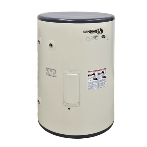
SANCO2Heat Pump – Installation Manual
Page 7 of 44
Sanden Heat Pump –Installation Manual
Page 7 of 40
Note:
The entire system is set up and fully functional when supplied. Once all the water and
electric connections have been made, the system will operate automatically provided that
mains power is available.
The only adjustments to the unit are to set the desired hot water supply temperature & set
the current time on the operation panel under the top housing cover, especially if the block
out time setting is desired. See Set point adjustment, current time setting, and block out
time section on page 19.
Figure 5: Heat pump installation example and dimensions
Attach the drain elbow to the drain opening located on the bottom of the heat pump
unit. The drain elbow is included in the installation kit for the heat pump unit.
Attach a drain hose with 5/8 inch (16mm) of inner diameter to the drain elbow to guide
the drained water to an appropriate drain.
Water Piping Installation – Heat Pump Unit & Tank
All piping that connects to the water supply must be installed by a licensed contractor.
The water supplied to the system must comply with the potable water quality standard.
Use of water that does not comply with this standard could result in a malfunction of
the system.
TDS
(Total
Dissolved
Solids)
Total
Hardness
(calcium Ion
concentration)
Up to
200ppm or
12 grains
hardness
The water supply must have a pressure of 29 PSI (200 kPa) or higher.
A drain trap must be installed on the drain pipe if water is to be drained to a drain pan.
Unit Weight
106lbs
(㼀㻻㻼㻌㼂㻵㻱㼃)
4.82"22.83"
4.82"
16.24"
14.02"
0.59"12.88"
1.41"
DRAIN CONNECTOR
Unit:inch
top housing cover & especially if the block out time setting is desired.
Sanden Heat Pump –Installation Manual
Page 6 of 40
Figure 4: Restrictions on installation with the space between the tank unit and the
heat pump unit
Heat pump Unit Installation
The surface to which the heat pump unit is installed must be firm, preferably a
concrete pad or block. If the surface is firm there is no need to fix the unit to a base
surface, unless there is a likelihood of high wind or local vibration.
If the heat pump unit and tank unit are to fixed, appropriate fixing devices for the
weight/expected duty should be used. It is permissible to install the Heat Pump on
the side of a wall provide an adequate support is used.
Note: For California installation the Tank section water heater must be braced,
anchored, or strapped to avoid falling or moving during an earthquake. For Tank
size over 52 Gallons (236l) consult your local building jurisdiction for appropriate
bracing designs.
Note: For Florida installation the Heat Pump unit should be installed in accordance
with all local codes regarding Hurricane winds.
Use appropriately treated lumber or pre-fabricated “pump ups” to raise the Heat
Pump unit 4”-6” from the ground – this will allow defrost condensate to drain. In
areas with significant snowfall ensure unit is mounted above the anticipated
snowfall depth.
A Pressure Relief (PR) valve MUST be installed during the installation of the tank
unit. This is installed in a defined point near the top of the tank unit. The PR Valve
must have clear drainage where escaping steam or water can flow freely. PR Valve
setting should be 100 Psig.
The installation site must be well drained so that any water accumulating (such as
rain or pipe leakage) will drain away and not enter the heat pump unit and the tank
unit.
Supply water pressure must be a minimum of 29 PSI (200 kPa) to ensure Heat
Pump unit operation – If pressure is below 29 PSI install a booster pump to water
supply.
Keep the piping run to a minimum
as the longer the pipe run, the
greater the potential for heat loss
(A) Difference in height between
the base of tank and base of
Heat pump should be no more
line between Tank & Heat Pump
long radius bends not street “L’s”
Unit Weight
GS4-45HPC:108lbs
GS4-45HPC-D:110lbs
(GS4-45HPC-D does not include a drain elbow.)
Sanden Heat Pump –Installation Manual
Page 7 of 40
Note:
The entire system is set up and fully functional when supplied. Once all the water and
electric connections have been made, the system will operate automatically provided that
mains power is available.
The only adjustments to the unit are to set the desired hot water supply temperature & set
the current time on the operation panel under the top housing cover, especially if the block
out time setting is desired. See Set point adjustment, current time setting, and block out
time section on page 19.
Figure 5: Heat pump installation example and dimensions
Attach the drain elbow to the drain opening located on the bottom of the heat pump
unit. The drain elbow is included in the installation kit for the heat pump unit.
Attach a drain hose with 5/8 inch (16mm) of inner diameter to the drain elbow to guide
the drained water to an appropriate drain.
Water Piping Installation – Heat Pump Unit & Tank
All piping that connects to the water supply must be installed by a licensed contractor.
The water supplied to the system must comply with the potable water quality standard.
Use of water that does not comply with this standard could result in a malfunction of
TDS
(Total
Dissolved
Solids)
Total
Hardness
(calcium Ion
concentration)
Up to
200ppm or
12 grains
hardness
The water supply must have a pressure of 29 PSI (200 kPa) or higher.
A drain trap must be installed on the drain pipe if water is to be drained to a drain pan.
Unit Weight
106lbs
(㼀㻻㻼㻌㼂㻵㻱㼃)
GS4 Unit Mounting Feet
Front Foot
Use 3/8” Diameter Screws
Slot Width “A” 7/16”
Slot Length “B” ¾”
Foot Length “C” 1”
Foot Width “D” 2”
C
B
A
D
Rear Foot
Use 3/8” Diameter Screws
Cut Out Width “A” 7/16”
Cut Out Length “B” ¾”
Foot Length “C” 1”
Foot Width “D” 2”
D
GS4 Unit Mounting Feet
Front Foot
Use 3/8” Diameter Screws
Slot Width “A” 7/16”
Slot Length “B” ¾”
Foot Length “C” 1”
Foot Width “D” 2”
C
B
A
A
B
C
D
Rear Foot
Use 3/8” Diameter Screws
Cut Out Width “A” 7/16”
Cut Out Length “B” ¾”
Foot Length “C” 1”
Foot Width “D” 2”
D
Sanden Heat Pump –Installation Manual
Page 7 of 40
Note:
The entire system is set up and fully functional when supplied. Once all the water and
electric connections have been made, the system will operate automatically provided that
mains power is available.
The only adjustments to the unit are to set the desired hot water supply temperature & set
the current time on the operation panel under the top housing cover, especially if the block
out time setting is desired. See Set point adjustment, current time setting, and block out
time section on page 19.
Figure 5: Heat pump installation example and dimensions
Attach the drain elbow to the drain opening located on the bottom of the heat pump
unit. The drain elbow is included in the installation kit for the heat pump unit.
Attach a drain hose with 5/8 inch (16mm) of inner diameter to the drain elbow to guide
the drained water to an appropriate drain.
Water Piping Installation – Heat Pump Unit & Tank
All piping that connects to the water supply must be installed by a licensed contractor.
The water supplied to the system must comply with the potable water quality standard.
Use of water that does not comply with this standard could result in a malfunction of
the system.
TDS
(Total
Dissolved
Solids)
Total
Hardness
(calcium Ion
concentration)
Up to
200ppm or
12 grains
hardness
The water supply must have a pressure of 29 PSI (200 kPa) or higher.
A drain trap must be installed on the drain pipe if water is to be drained to a drain pan.
Unit Weight
106lbs
(㼀㻻㻼㻌㼂㻵㻱㼃)
set the current time on the operation panel under the
Front Foot
Use 3/8" Diameter Screws
Rear Foot
Use 3/8" Diameter Screws
4
"A" 7/16"
"B" 3/4"
"C" 1"
"D" 2"
Sanden Heat Pump –Installation Manual
Page 6 of 40
Figure 4: Restrictions on installation with the space between the tank unit and the
heat pump unit
Heat pump Unit Installation
The surface to which the heat pump unit is installed must be firm, preferably a
concrete pad or block. If the surface is firm there is no need to fix the unit to a base
surface, unless there is a likelihood of high wind or local vibration.
If the heat pump unit and tank unit are to fixed, appropriate fixing devices for the
weight/expected duty should be used. It is permissible to install the Heat Pump on
the side of a wall provide an adequate support is used.
Note: For California installation the Tank section water heater must be braced,
anchored, or strapped to avoid falling or moving during an earthquake. For Tank
size over 52 Gallons (236l) consult your local building jurisdiction for appropriate
bracing designs.
Note: For Florida installation the Heat Pump unit should be installed in accordance
with all local codes regarding Hurricane winds.
Use appropriately treated lumber or pre-fabricated “pump ups” to raise the Heat
Pump unit 4”-6” from the ground – this will allow defrost condensate to drain. In
areas with significant snowfall ensure unit is mounted above the anticipated
snowfall depth.
A Pressure Relief (PR) valve MUST be installed during the installation of the tank
unit. This is installed in a defined point near the top of the tank unit. The PR Valve
must have clear drainage where escaping steam or water can flow freely. PR Valve
setting should be 100 Psig.
The installation site must be well drained so that any water accumulating (such as
rain or pipe leakage) will drain away and not enter the heat pump unit and the tank
unit.
Supply water pressure must be a minimum of 29 PSI (200 kPa) to ensure Heat
Pump unit operation – If pressure is below 29 PSI install a booster pump to water
supply.
Keep the piping run to a minimum
as the longer the pipe run, the
greater the potential for heat loss
(A) Difference in height between
the base of tank and base of
Heat pump should be no more
line between Tank & Heat Pump
long radius bends not street “L’s”


