13
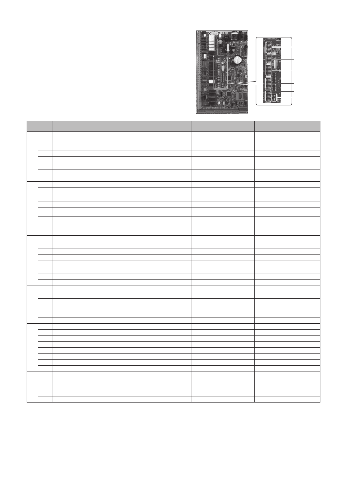
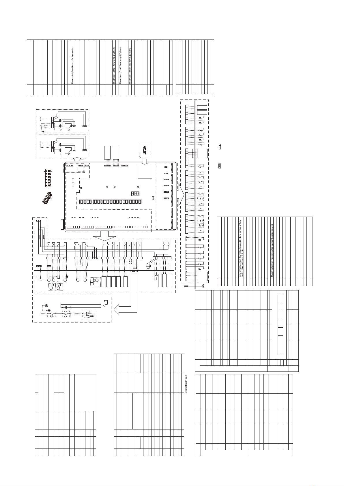
FTC WIRING DIAGRAM <PAC-IF07*B-E> Symbol Name
TB1 Terminal block <Power supply, Outdoor unit>
ECB2
Earth leakage circuit breaker for immersion heater
(Except PAC-IF071B-E)
MP1
Water circulation pump 1(Space heating & DHW)
MP2 Water circulation pump 2
(Space heating for Zone1)(Local supply)
MP3 Water circulation pump 3
(Space heating for Zone2)(Local supply)
MP4
Water circulation pump 4 (DHW)(Local supply)
3WV
(2WV1)
3-way valve (2-way valve 1)(Local supply)
2WV2a 2-way valve (For Zone 1)(Local supply)
2WV2b 2-way valve (For Zone 2)(Local supply)
MXV Mixing valve (Local supply)
IHT
heater(Except PAC-IF071B-E)
IH Immersion heater(Except PAC-IF071B-E)
IHC Contactor for immersion heater
(Except PAC-IF071B-E)
TH1 Thermistor (Room temp.)(Option)
TH2 Thermistor (Ref. liquid temp.)
(Included in PAC-IF071B-E)
THW1 Thermistor (Flow water temp.)
THW2 Thermistor (Return water temp.)
THW5A Thermistor (DHW tank upper water temp.)
(Included in PAC-IF073B-E)
THW5B Thermistor (DHW tank lower water temp.)
(Included in PAC-IF073B-E)
(Option for PAC-IF071/072B-E)
THW6
THW7 Thermistor (Zone1 return temp.)(Option)
THW8
THW9 Thermistor (Zone2 return temp.)(Option)
THW10 Thermistor (Mixing tank temp.)(Option)
THWB1
IN1 Room thermostat 1 (Local supply)
IN2 Flow switch 1 (Local supply)
IN3 Flow switch 2 (Local supply)
IN4 Demand control (Local supply)
IN5 Outdoor thermostat (Local supply)
IN6 Room thermostat 2 (Local supply)
IN7 Flow switch 3 (Local supply)
IN8 Electric energy meter 1 (Local supply)
IN9 Electric energy meter 2 (Local supply)
IN10 Heat meter (Local supply)
IN11 Smart grid ready input (Local supply)
IN12
INA1 Flow sensor (Option)
FLOW TEMP. CONTROLLER (FTC)
TBO.1-5
Terminal block <Outputs>
TBI.1-6 Terminal block <Signal Inputs, Thermistor>
F1 Fuse (IEC T10AL250V)
F2 Fuse (IEC T6.3AL250V)
SW1-6 DIP switch *See Table 3
X1-16 Relay
LED1 Power supply (FTC)
LED2 Power supply (Main remote controller)
LED3 Communication (FTC-Outdoor unit)
LED4 Reading or writing data to SD card
CNPWM
Pump speed control signal for MP1
CN108 SD card connector
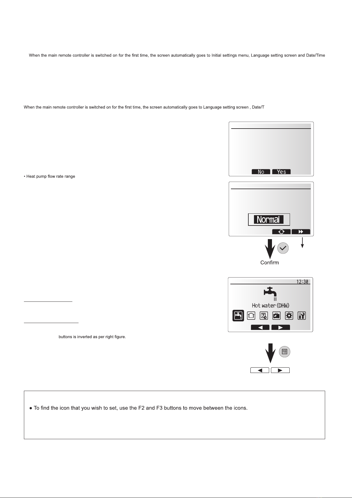
1. Symbols used in wiring diagram are, : connector, : terminal block. Function with asterisk (*) may not be available depending on model types.
2. Indoor unit and outdoor unit connecting wires have polarities, make sure to match terminal numbers (S1, S2, S3) for correct wirings.
3. Since the outdoor unit side electric wiring may change, be sure to check the outdoor unit electric wiring diagram for service.
4. When connecting a booster heater, the wiring method is different according to the type of built-in thermostat.
Please refer to the installation manual for details.
Table 4 Error Codes
Code Error
L3 Circulation water temperature overheat protection
L4 DHW tank water temperature overheat protection
L5 Indoor unit temperature thermistor (THW1, THW2, THW5B,
THW6, THW7, THW8, THW9) failure
L6 Circulation water freeze protection
L8 Heating operation error
L9
LA Pressure sensor failure
LB High pressure protection
LC Boiler circulation water temperature overheat protection
LD
Boiler temperature thermistor (THWB1) failure
LE Boiler operation error
LF Flow sensor failure
LH Boiler circulation water freeze protection
LJ DHW operation error (type of external plate HEX)
LL Setting errors of DIP switches on FTC control board
LP
P1 Thermistor (Room temp.) (TH1) failure
P2 Thermistor (Ref. liquid temp.) (TH2) failure
P6 Anti-freeze protection of plate heat exchanger
J0 Communication failure between FTC and wireless receiver
J1 - J8
Communication failure between wireless receiver and
wireless remote controller
J9
Communication failure between FTC (Master) and FTC
(Slave)
E0 - E5 Communication failure between main remote controller and
FTC
E6 - EF
Communication failure between FTC and outdoor unit
E9 Outdoor unit receives no signal from indoor unit.
EE Outdoor unit incorrect connection
U*, F*,A*
Outdoor unit failure
Table 1 Signal Inputs
Name
Terminal block
Connector
Item OFF (Open) ON (Short)
IN1 TBI.1 7-8 — Room thermostat
1 input *1
Refer to SW2-1 in
<Table 3 DIP Switch Functions>.
IN2 TBI.1 5-6 — Flow switch 1
input
Refer to SW2-2 in
<Table 3 DIP Switch Functions>.
IN3 TBI.1 3-4 — Flow switch 2
input (Zone1)
Refer to SW3-2 in
<Table 3 DIP Switch Functions>.
IN4 TBI.1 1-2 — Demand control
input Normal Heat source OFF/
Boiler operation *3
IN5 TBI.2 7-8 — Outdoor thermo-
stat input *2
Standard opera-
tion
Heater operation/
Boiler operation *3
IN6 TBI.2 5-6 — Room thermostat
2 input *1
Refer to SW3-1 in
<Table 3 DIP Switch Functions>.
IN7 TBI.2 3-4 — Flow switch 3
input (Zone2)
Refer to SW3-2 in
<Table 3 DIP Switch Functions>.
IN8 TBI.3 7-8 — Electric energy
meter 1
Refer to installation manual.
IN9 TBI.3 5-6 — Electric energy
meter 2
IN10
TBI.2 1-2 — Heat meter
IN11
TBI.3 3-4 — Smart grid ready
input
IN12
TBI.3 1-2 —
INA1
TBI.4 1-3 CN1A Flow sensor
*1. Set the ON/OFF cycle time of the room thermostat for 10 minutes or more;
otherwise the compressor may be damaged.
*2. If using outdoor thermostat for controlling operation of heaters, the lifetime of the
heaters and related parts may be reduced.
*3. To turn on the boiler operation, use the main remote controller to select “Boiler” in
“External input setting” screen in the service menu.
Table 2 Outputs
Name
Terminal block
Connector
Item OFF ON
OUT1
TBO.1 1-2 CNP1 Water circulation pump 1 output
(Space heating/cooling & DHW) OFF ON
OUT2
TBO.1 3-4 — Water circulation pump 2 output
(Space heating/cooling for Zone1) OFF ON
OUT3
TBO.1 5-6 —
Water circulation pump 3 output
(Space heating/cooling for Zone2) *1 OFF ON
2-way valve 2b output *2
OUT4
TBO.2 4-6 CNV1 3-way valve (2-way valve) output Heating DHW
OUT5
TBO.2 1-2 — Mixing valve output *1 Stop Close
TBO.2 2-3 Open
OUT6
TBO.5 5-6 — Booster heater 1 output OFF ON
OUT7
TBO.5 7-8 — Booster heater 2 output OFF ON
OUT8
TBO.4 7-8 — Cooling signal output OFF ON
OUT9
TBO.4 5-6 CNIH Immersion heater output OFF ON
OUT10
TBO.3 1-2 — Boiler output OFF ON
OUT11
TBO.3 5-6 — Error output Normal Error
OUT12
TBO.3 7-8 — Defrost output Normal Defrost
OUT13
TBO.4 3-4 — 2-way valve 2a output *2 OFF ON
OUT14
— CNP4 Water circulation pump 4 output
(DHW) OFF ON
OUT15
TBO.4 1-2 — Comp. ON signal OFF ON
OUT16
TBO.3 3-4 — Thermo ON signal OFF ON
OUTA1
TBI.4 7-8 — Analog output 0V-10V
BC
TBO.5 3-4 — Booster heater protection output
OFF(BHT Open) ON(BHT Short)
BHT
TBO.5 1-2
CNBHT
Thermostat for booster heater
Thermostat normal: Short High temp. open
Do not connect to the terminals that are indicated as “—” in the “T
*1. For 2-zone temperature control.
*2. For 2-zone valve ON/OFF control.
CN108
CN01
(BK)
1
3
CN3C
(BU)
1
3
CNPWM
(WH)
1
5
CNRF
(WH)
Wireless receiver
(Option)
1
5
CN105
(RD)
WiFi adapter
(Option)
1
5
CNIT
(BU)
1
2
CN20
(RD)
1
3
CN21
(YE)
1
4
CNW12
(RD)
CNW5
(BU)
1
4
CN1A
(WH)
TBI.1
LED1
LED2
LED3
LED4
TAB1
1
8
1
8
1
8
1
8
1
6
SW1
SW2
SW3
SW4
SW5
F1
IECT10AL250V
F2
IECT6.3AL250V
1
2
3
4
5
6
1
2
3
4
5
6
1
2
3
4
5
6
7
8
1
2
3
4
5
6
7
8
1
3
1
3
CNBHT
(BK)
CNIH
(OG)
CNV1
(WH)
CNP4
(RD)
CNP1
(WH)
TBO.1
TBO.2
TBO.3
TBO.4
1
2
3
4
5
6
7
8
TBO.5
1
3
5
1
3
CNP4
(RD)
F1
F2
CN01
(BK)
TBO.1
X1
X2
X3
X14
1
3
3
CNPWM
(WH)
CNP1
(WH)1
3
M
1~
2WV2b
MP3
MP4
1
2
3
4
5
6
TBO.2
1
3
5
CNV1
(WH)
3WV
1
2
3
4
5
6
7
8
TBO.3
X4
X10
X16
X11
X12
TBO.4
1
2
3
4
5
6
7
8
TBO.5
X15
X13
X9
X8
Signal output
(Boiler)
Signal output
(thermo on)
Signal output
(Error)
Signal output
(Defrost)
Signal output
(Comp. on)
CNIH
(OG)2WV2a
1
3
X6
X7
N
(3)
L
(1)
42
BU
RD
31 5 A1
42 6 A2
IHT
IH
BA
BU
RD
1
3
2
CNIH
(OG)
OG
OG
Power supply
to Immersion heater
(Except PAC-IF071B-E)
~/N230V 50Hz
ECB2
IHC
1
5
3
1
5
3
1
3
1
3
FTC board
X5B
X5A
MXV
Close
N
Open
MP2
MP1
M
1~
M
1~
TBI.2TBI.3TBI.4TBI.5TBI.6
12345678 12345678 12345678 12345678 12345678 12345678
1
2
3
4
5
6
1
4
t° t° t°
12345678
IN4IN3IN2IN1
12345678
IN10IN7IN6IN5
12345678
IN12IN9IN8 IN11
12345678
OUTA1
Flow
Sensor
12345678
t°
THW6 THW7 THW8 THW9
t° t°
12345678
THWB1 THW 10
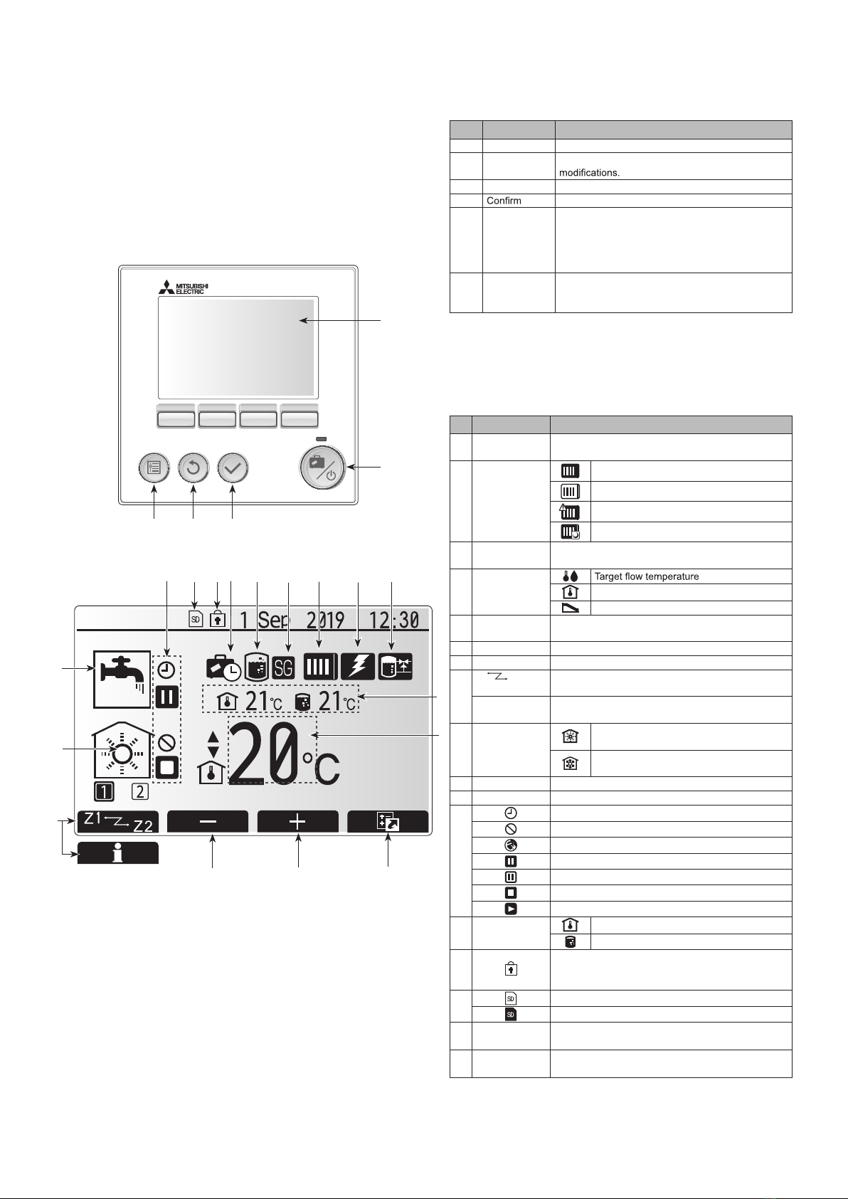
Main remote
controller
FTC
(Slave)
TBI.1 TBI.2 TBI.3 TBI.4 TBI.5TBI.6
CN20
(RD)
t°
CN21
(YE)
1 3 1 2
CNW12
(RD)
1 4
CNW5
(BU)
t°
TAB1
THTH1TH2 *
THW5B *
- + + -
V
- + - +
14
t° t°t°
THW2THW1
1
5
SW6
M
1~
M
1~
M
1~
M
1~
M
1~
NL
S3S2S1
NL
S3S2S1
To outdoor
unit
TB1
OG OG
YE
YE
GNYE
To outdoor
unit
Power supply
~/N 230V 50Hz
TB1
OG
BU
RD
BU
RD
YE
GNYE
1
3
1
3
OG
BN
OG
BN
Indoor unit powered
by independent source
Indoor unit powered
via outdoor unit
CIRCUIT
BREAKER
1
3
5
CN3C
(BU)
CN3C
(BU)
CN01
(BK)
OG
YE
1
3
5
CN01
(BK)
2WV1
M
1~
4 5 6
TBO.2
1
2
3
4
5
6
7
8
Signal output for booster
heater protection
Signal output
(booster heater 1)
Signal output
(booster heater 2)
CN1A
(WH)
1 4
<How to use TBO.1 to 5>
1 4
Pressre
Sensor *
CN401
(WH)
1
4
CN401
(WH)
t°
THW5A *
1
BHT
CNBHT
(BK)
3
Tool
Tool
Conductor Conductor
Outline view Top view
Connect them using either way as shown below.
*1. External output (OUT11) will be available. For safety reasons, this function is not available for certain errors. (In that case, system operation must be stopped and only the
water circulation pump keeps running.)
*2. This switch functions only when the FTC unit is connected with a PUHZ-FRP outdoor unit. When another type of outdoor unit is connected, the heating mode function is
active regardless of the fact that this switch is ON or OFF.
*3. Space heating and DHW can be operated only in indoor unit, like an electric heater.
*4. If emergency mode is no longer required, return the switch to OFF position.
*5. Active only when SW3-6 is set to OFF.
*6. Active only when SW4-1 is set to ON.
Table 3 DIP switch functions
DIP switch Function OFF ON Default settings:
Indoor unit model
SW1
SW1-1
Boiler WITHOUT
Boiler WITH Boiler OFF
SW1-2
Heat pump maxi-
mum outlet water
temperature
55ºC 60ºC ON
SW1-3
DHW tank WITHOUT
DHW tank
WITH DHW
tank
OFF : PAC-IF071B-E
ON : Except
: PAC-IF071B-E
SW1-4
Immersion heater WITHOUT Im-
mersion heater
WITH Immer-
sion heater
OFF : PAC-IF071B-E
ON : Except
: PAC-IF071B-E
SW1-5
Booster heater WITHOUT
Booster heater
WITH Booster
heater
OFF
SW1-6
Booster heater
function
For heating
only
For heating
and DHW
OFF
SW1-7
Outdoor unit type Split type Packaged type
OFF : PAC-IF071B-E
ON : Except
: PAC-IF071B-E
SW1-8
Wireless remote
controller
WITHOUT
Wireless re-
mote controller
WITH Wireless
remote control-
ler
OFF
SW2
SW2-1
Room thermostat 1
input (IN1) logic
change
Zone1 opera-
tion stop at ther-
mostat short
Zone1 opera-
tion stop at ther-
mostat open
OFF
SW2-2
Flow switch 1 input
(IN2) logic change
Failure detec-
tion at short
Failure detec-
tion at open OFF
SW2-3
Booster heater
capacity restriction Inactive Active OFF
SW2-4
Cooling mode func-
tion Inactive Active OFF
SW2-5
Automatic switch to
backup heat source
operation (When
outdoor unit stops
by error)
Inactive Active *1 OFF
SW2-6
Mixing tank WITHOUT Mix-
ing tank
WITH Mixing
tank OFF
SW2-7
2-zone temperature
control Inactive Active *5 OFF
SW2-8
Flow sensor WITHOUT
Flow sensor
WITH Flow
sensor OFF
DIP switch Function OFF ON Default settings:
Indoor unit model
SW3
SW3-1
Room thermostat
2 input (IN6) logic
change
Zone2 opera-
tion stop at ther-
mostat short
Zone2 opera-
tion stop at ther-
mostat open
OFF
SW3-2
Flow switch 2 and 3
input logic change
Failure detec-
tion at short
Failure detec-
tion at open OFF
SW3-3
— — — OFF
SW3-4
Electric energy
meter
WITHOUT
Electric energy
meter
WITH Electric
energy meter OFF
SW3-5
Heating mode function *2
Inactive Active ON
SW3-6
2-zone valve ON/
OFF control Inactive Active OFF
SW3-7
Heat exchanger for DHW
Coil in tank
External plate HEX
OFF
SW3-8
Heat meter WITHOUT
Heat meter
WITH Heat
meter OFF
SW4
SW4-1
Multiple outdoor control
Inactive Active OFF
SW4-2
Position of multiple
outdoor units
control *6
Slave Master OFF
SW4-3
— — — OFF
SW4-4
Indoor unit only
operation (during
installation work) *3
Inactive Active OFF
SW4-5
Emergency mode
(Heater only opera-
tion)
Normal
Emergency mode
(Heater only
operation)
OFF *4
SW4-6
Emergency mode
(Boiler operation) Normal
Emergency
mode
(Boiler operation)
OFF *4
SW5
SW5-1
— — — OFF
SW5-2
Advanced auto adaptation
Inactive Active ON
SW5-3
Capacity code
SW5-3 SW5-4 SW5-5 SW5-6 SW5-7
PAC-IF07*B-E OFF OFF OFF OFF OFF
SW5-4
SW5-5
SW5-6
SW5-7
SW5-8
— — — OFF
SW6
SW6-1
— — —
OFF : PAC-IF071/072B-E
ON : PAC-IF073B-E
SW6-3
Pressure sensor Inactive Active OFF
SW6-4
Analog output Inactive Active OFF
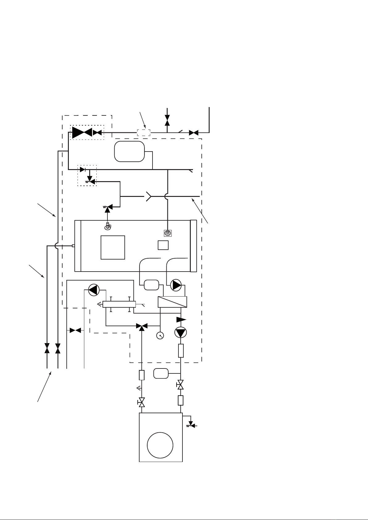
WIRING DIAGRAM