7
OUTLET/TERMINAL FITTINGS (TAPS, ETC.)
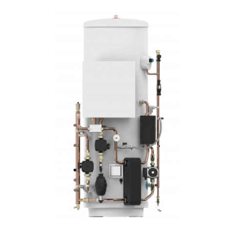
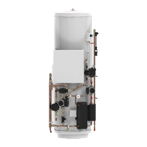
The Pre-plumbed cylinder can be used in conjunction with most types of terminal ttings, plumbing ttings and pipework.
However, the rated pressures of any ttings selected should be checked for compatibility before installation.
NOTE: Accessories, plumbing ttings and pipe work should have a rated operating pressure of at least 8 bar.
Outlets situated higher than the cylinder will give outlet pressures lower than that at the unit, a 10m height
dierence will result in a 1 bar pressure reduction at the outlet tting.
LIMITATIONS
The Pre-plumbed cylinder should not be used in association with any of the following:
• Solid fuel boilers or any other boiler in which the energy input is not under eective thermostatic control, unless additional
and appropriate safety measures are installed.
• Ascending spray type bidets or any other class 1 back syphonage risk require that a type A air gap be employed.
• Steam heating plants unless additional and appropriate safety devices are installed.
• Situations where maintenance is likely to be neglected or safety devices tampered with.
• Water supplies that have either inadequate pressure or where the supply may be intermittent.
• Situations where it is not possible to safely pipe away any discharge from the safety valves.
• In areas where the water consistently contains a high proportion of solids, e.g. suspended matter that could block the
strainer unless adequate ltration can be ensured.
OPERATIONAL SUMMARY
Maximum mains supply pressure 1.6 MPa (16 bar)
Operating pressure 0.35 MPa (3.5 bar)
Expansion vessel pressure 0.35 MPa (3.5 bar)
Maximum design (Rated) pressure 0.8 MPa (8 bar)
Expansion relief valve setting 0.8 MPa (8 bar)
T&P relief valve setting 90°C/1.0 MPa (10 bar)
T&P relief valve manufacturers ref RWC PTEM 510003
Maximum primary circuit pressure 0.3 MPa (3 bar)
Maximum heating uid temperature 85oC
Storage capacity See Table 1 below
Weight when full See Table 1 below
OUTLINE SPECIFICATIONS
The cylinders are designed, constructed and tested for compliance with BS EN 12897:2016
Outer casing: White pre-painted corrosion resistant steel
Water container: Duplex stainless steel. 100% pressure tested to 1.5 MPa (15 bar).
Thermal insulation: CFC/HCFC free re retardant expanded polyurethane foam with zero ozone depletion potential. It has a
Global Warming Potential (GWP) of 3.1. Nominal thickness: Standard units 60mm - Slimline units 50mm.
Table 1 - Unit Weights & Standing Heat Loss
Model Type
Nominal
Capacity
(litres)
Weight of
full unit (kg)
Weight of
unit (kg)
Standing Heat Loss
per day (kWh/24h) per year (kWh/365d)
Standard 150 205 55 1.15 419.7
Standard 170 228 58 1.23 448.9
Standard 210 (Small) 274 64 1.53 558.5
Standard 210 (Large) 278 68 1.53 558.2
Standard 250 324 74 1.80 657.0
Standard 300 382 82 2.06 751.9
Slimline 150 209 59 1.40 511.0
Slimline 170 233 63 1.59 580.4
IMPORTANT INSTALLATION NOTE
WHERE THE INLET SUPPLY TO THE PRESSURE REDUCING VALVE (PRV) IS ROUTED THROUGH A HEATED SPACE
AND IS FITTED WITH A CHECK VALVE OR OTHER FITTING THAT WOULD PREVENT BACK FLOW, HIGH PRESSURES
CAN BE EXPERIENCED IN THE INLET PIPE DUE TO WARMING THAT CAN CAUSE DAMAGE TO THE PRV OR OTHER
FITTINGS ON THE INLET SUPPLY. IN THESE CIRCUMSTANCES, THE INSTALLATION OF A MEANS TO ACCOMMODATE
EXPANSION AND THUS LIMIT THE PRESSURE RISE IN THE INLET PIPE IS RECOMMENDED. REFER TO THE
INSTALLATION SECTION FOR FURTHER DETAILS.


