Econ NE-F50SP/R4INV-PA User manual

DC INVERTER SWIMMING POOL HEAT PUMP
SERIES USER MANUAL
Please read this manual carefully before using and keep it in a safe place.


Contents
I. Unit Parameters.............................................................................................................................................. 1
II. System Specification.....................................................................................................................................4
1. Specification............................................................................................................................................4
2. Unit Dimensions................................................................................................................................... 10
3. Explosion View..................................................................................................................................... 13
III. Installation Instructions.............................................................................................................................. 14
IV. Running Test.............................................................................................................................................. 18
1. Inspection Before Running Test........................................................................................................ 19
2. Control Function Description..............................................................................................................19
V. Maintenance................................................................................................................................................ 32
VI. Wi-Fi Module and APP User Manual...................................................................................................... 33
1. Display................................................................................................................................................... 33
2. Wi-Fi Function...................................................................................................................................... 33
2.2 Software startup..............................................................................................................................34
2.3 Software registration and configuration.......................................................................................34
2.4 Software function operation.......................................................................................................... 42
1
I. Unit Parameters
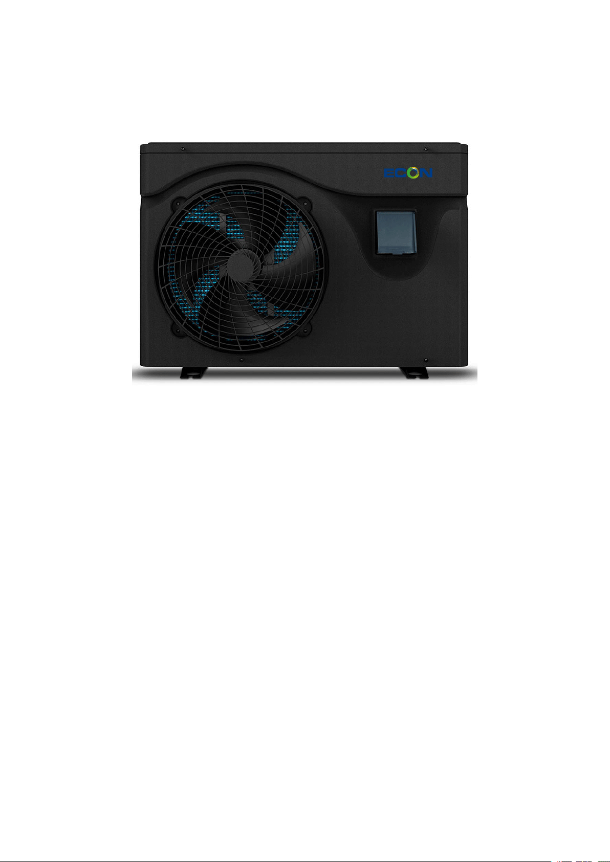
1. Appearance
2. Statement
To keep users under safe working condition and property safety, please follow the instructions
below.
Wrong operation may result in injury or damage;
Please install the unit in compliance with local laws, regulations and standards;
Confirm power voltage and frequency;
The unit is only used with grounding sockets;
Independent switch must be offered with the unit.
3. The following safety factors need to be considered:
Please read the following warnings before installation;
Be sure to check the details that need attention, including safety factors;
After reading the installation instructions, be sure to save them for future reference.
⚠Warning
Make sure that the unit is installed safely and reliably.

2
If the unit is not secure or not installed, it may cause damage. The minimum support weight
required for installation is 21g/mm2.
If the unit was installed in a closed area or limited space, please consider the size of room and
ventilation to prevent suffocation caused by refrigerant leakage.
Use a specific wire and fasten it to terminal block so that the connection will prevent pressure
from being applied to parts.
Wrong wiring will cause fire.
Please connect power wire accurately according to wiring diagram on the manual to avoid burnout of
the unit or fire.
Be sure to use correct material during installing.
Wrong parts or wrong materials may result in fire, electric shock, or falling of the unit.
Install on the ground safely, please read installation instructions.
Improper installation may result in fire, electric shock, falling of the unit, or water leaking.
Use professional tools for doing electrical work.
If power supply capacity is insufficient or circuit is not completed, it may cause fire or electric shock.
The unit must have grounding device.
If power supply does not have grounding device, be sure not to connect the unit.
The unit should be only removed and repaired by professional technician.
Improper movement or maintenance of the unit may cause water leakage, electric shock, or fire.
Please find a professional technician to do.
Don't unplug or plug power during operation.It may cause fire or electric shock.
Don't touch or operate the unit when your hands are wet. It may cause fire or electric shock.
Don't place heaters or other electrical appliances near the power wire.It may cause fire or

3
electric shock.
The water must not be poured directly from the unit. Do not let water to permeate into the
electrical components.
4. ⚠Warning
Do not install the unit in a location where there may be flammable gas.
If there is flammable gas around the unit, it will cause explosion.
According to the instruction to carry out drainage system and pipeline work. If drainage system or
pipeline is defective, water leakage will occur. And it should be disposed immediately to prevent
other household products from getting wet and damage.
Do not clean the unit while power is on. Turn off power before cleaning the unit. If not it
may result in injury from a high-speed fan or electric shock.
Stop operating the unit once there is a problem or an fault code.
Please turn off power and stop running the unit. Otherwise it may cause electric shock or fire.
Be careful when the unit is not packed or not installed.
Pay attention to sharp edges and fins of heat exchanger.
After installation or repair, please confirm refrigerant is not leaking.
If refrigerant is not enough, the unit will not work properly.
The installation of external unit must be flat and firm.
Avoid abnormal vibration and noise.
Don’t put your fingers into fan and evaporator.
High speed running fan will result in serious injury.
This device is not designed for people who is physically or mentally weak (including
children) and who does not have experience and knowledge of heating and cooling
system. Unless it is used under direction and supervision of professional technician, or

4
has received training on the using of this unit. Children must use it under supervision of
an adult to ensure that they use the unit safely. If power wire is damaged, it must be
replaced by a professional technician to avoid danger.
II. System Specification
1. Specification
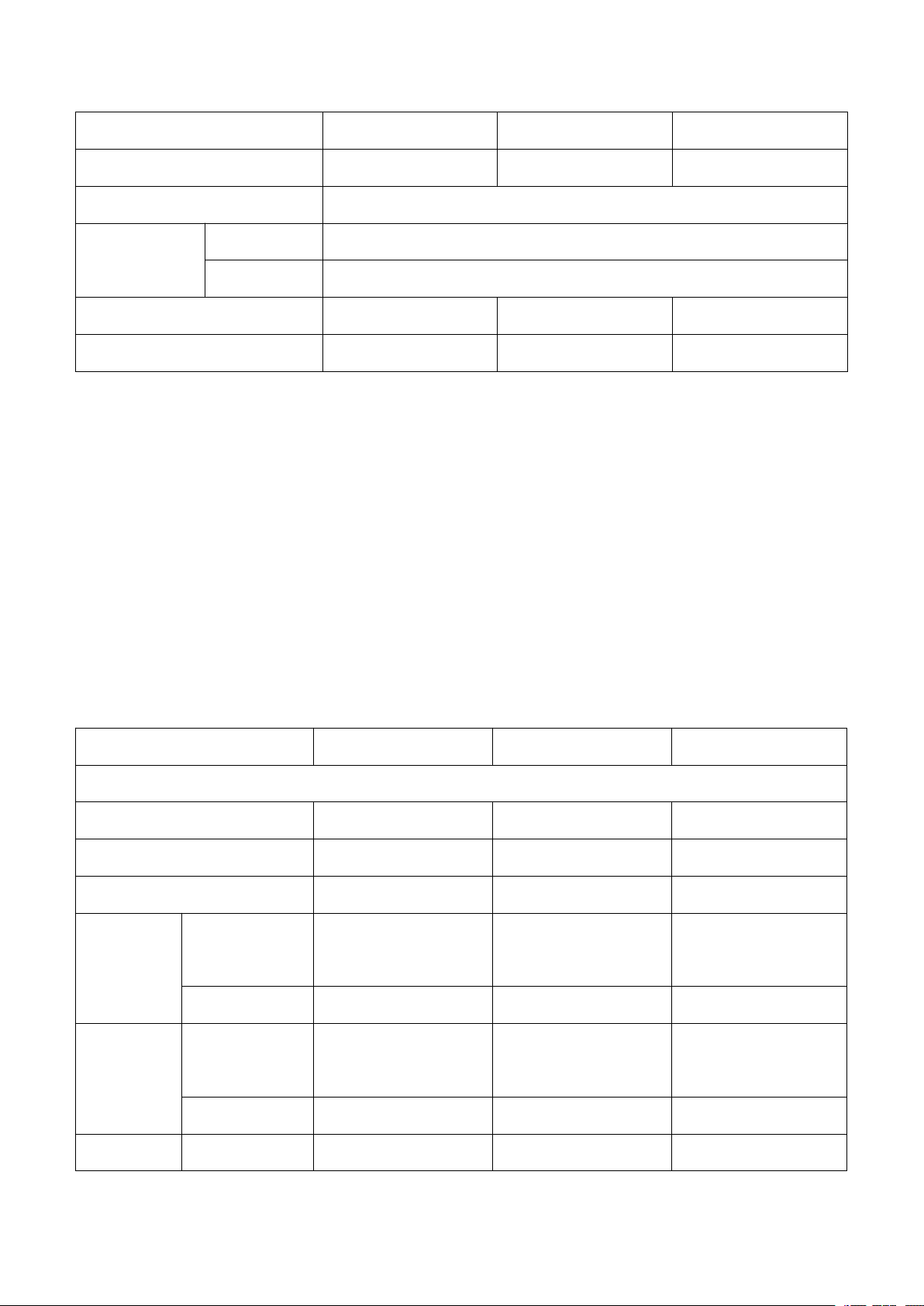
Model NE-F50SP/R4INV-PA NE-F70SP/R4INV-PA NE-F90SP/R4INV-PA
Ambient Temperature: (DB/WB) 27°C/24.3°C; Water Inlet/Outlet Temperature: 26°C/28°C.
Heating capacity(kW) 1.5~5.5 1.5~7.2 1.8~9.5
Power input (kW) 0.104~0.84 0.106~1.12 0.124~1.46
COP 14.4~6.55 14.2~6.43 14.5~6.5
Boost mode
Heating
capacity(kW)
5.5 7.2 9.5
COP 6.55 6.43 6.5
Smart mode
Heating
capacity(kW)
4.5 5.8 7.8
COP 7.41 7.53 7.52
Silent mode
Heating
capacity(kW)
2.1 2.8 3.5
COP 12.2 12.5 12.2
Ambient Temperature: (DB/WB) 15°C/12°C; Water Inlet Temperature: 26°C.
Heating capacity(kW) 1.1~3.9 1.3~5.4 1.5~7.9
Power input (kW) 0.138~0.75 0.168~1.102 0.194~1.491
COP 7.97~5.2 7.74~4.9 7.73~5.3
Boost mode
Heating
capacity(kW)
3.9 5.4 7.9
COP 5.2 4.9 5.3
Smart mode
Heating
capacity(kW)
3.1 4.3 6.1
COP 5.92 5.95 5.95

5
Silent mode
Heating
capacity(kW)
2.2 2.4 2.5
COP 6.95 6.88 6.92
Ambient Temperature: (DB/WB) 35°C/-; Water Inlet/Outlet Temperature: 30°C/28°
Cooling capacity(kW) 1.5~3.1 1.7~3.8 1.8~4.9
Power input (kW) 0.208~0.704 0.229~0.854 0.242~1.101
EER 7.2~4.4 7.42~4.45 7.44~4.45
Boost Mode
Cooling Capacity
(kW)
3.1 3.8 4.9
EER 4.4 4.45 4.45
Smart Mode
Cooling Capacity
(kW)
2.3 2.92 3.5
EER 5.64 5.63 5.63
Silent Mode
Cooling Capacity
(kW)
1.8 2.18 2.4
EER 6.97 6.97 6.95
Power supply 220-240V/50Hz
Max power input (KW) 1.31 1.61 1.75
Max current(A) 5.95 7.32 7.95
Heating temperature range 15°C~40°C
Running temperature range -10°C~43°C
Advised swimming pool size 10m³~20m³ 15m³~30m³ 20m³~40m³
Refrigerant R32
Compressor MITSUBISHI ELECTRIC (DC inverter)
Air side heat exchanger Hydrophilic fin exchanger
Water side heat exchanger Titanium tube heat exchanger
6
Water flow (m³/h) 2.4 3.1 4.1
Water pressure drop (kPa) 15 17 18
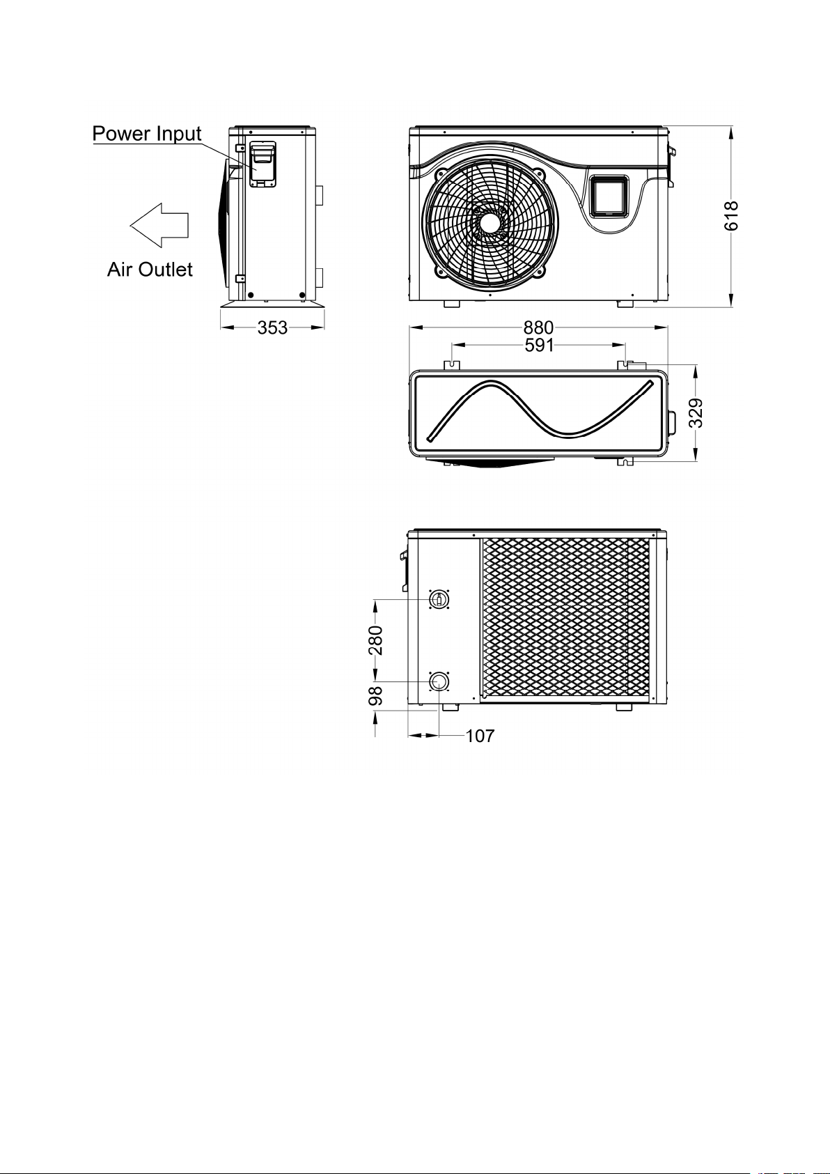
Net dimension LxWxH (mm) 880×353×618
Water pipe
Connection(mm)
Inlet 50
Outlet 50
Net weight (kg) 33 37 39
Noise level dB(A) 37~47 38~48 39~49
The technical specification of our heat pumps is provided for information purpose only. We reserve
the right to make change without notice in advance.
1. Noise at 1m, 4m and 10m comply with Directives EN ISO 3741 and EN ISO 354
2. Calculate according to an in-ground private swimming pool covered with bubble
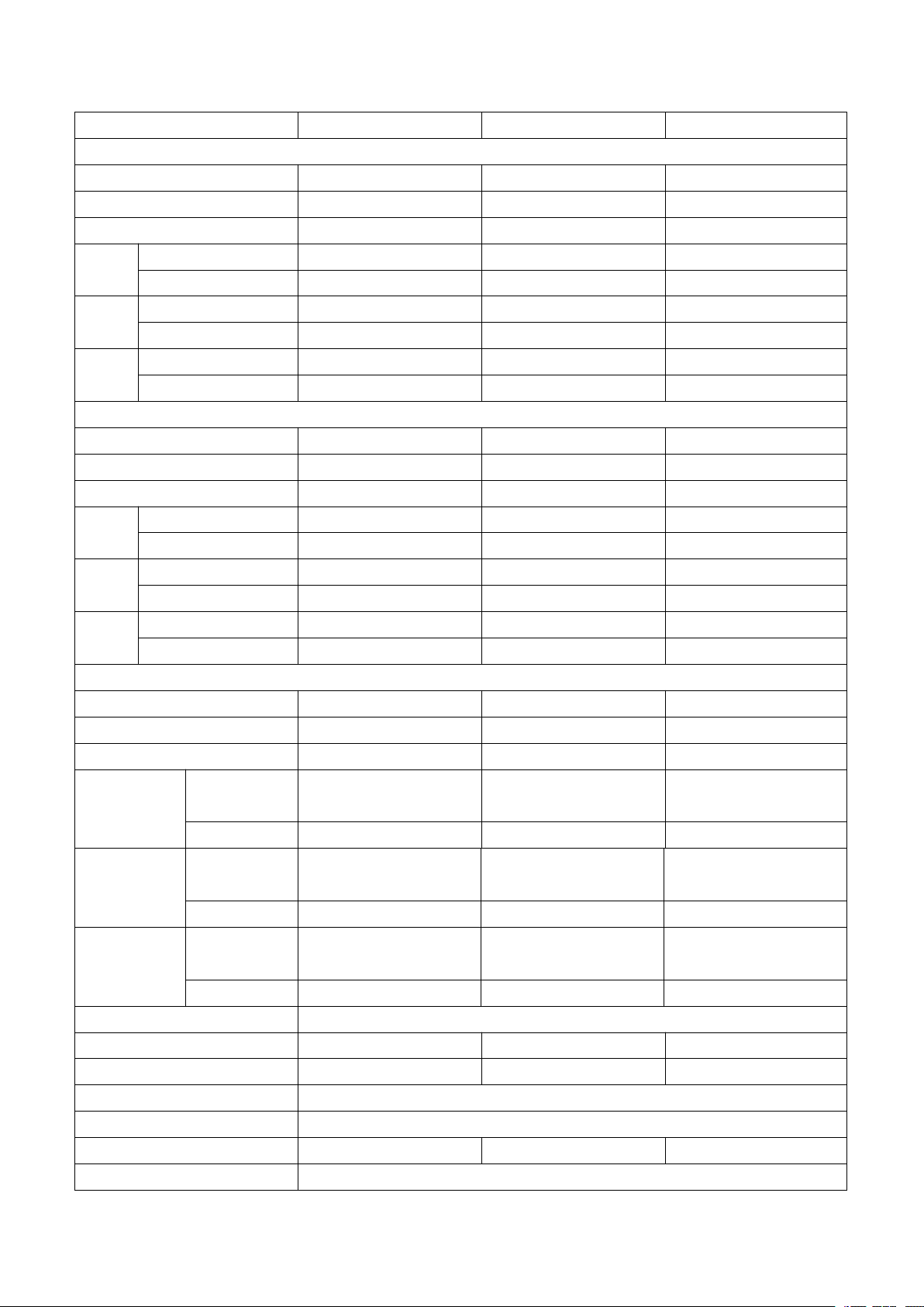
Model NE-F110SP/R4INV-PA NE-F150SP/R4INV-PA NE-F180SP/R4INV-PA
Ambient Temperature: (DB/WB) 27°C/24.3°C; Water Inlet/Outlet Temperature: 26°C/28°C.
Heating capacity(kW) 2.8~11.5 3.5~15.3 4.35~18
Power input (kW) 0.193~1.79 0.243~2.41 0.306~2.83
COP 14.5~6.4 14.4~6.35 14.2~6.36
Boost mode
Heating capacity
(kW)
11.5 15.3 18.0
COP 6.4 6.35 6.36
Smart mode
Heating capacity
(kW)
9.1 11.55 14.01
COP 7.82 7.68 7.5
Silent mode Heating capacity 5.5 7.35 8.7

7
(kW)
COP 11.2 10.62 10
Ambient Temperature: (DB/WB) 15°C/12°C; Water Inlet Temperature: 26°C.
Heating capacity(kW) 2.21~8.23 2.95~11.15 3.42~13.33
Power input (kW) 0.283~1.614 0.386~2.226 0.453~2.693
COP 7.81~5.1 7.64~5.01 7.55~4.95
Boost mode
Heating capacity
(kW)
8.23 10.86 13.33
COP 5.1 5.01 4.95
Smart mode
Heating capacity
(kW)
6.58 8.65 10.55
COP 5.73 5.72 5.68
Silent mode
Heating capacity
(kW)
4.37 5.55 6.72
COP 6.57 6.55 6.51
Ambient Temperature: (DB/WB) 35°C/-; Water Inlet/Outlet Temperature: 30°C/28°
Cooling capacity(kW) 2.42~6.3 3.35~7.95 4.11~9.82
Power input (kW) 0.327~1.438 0.452~1.811 0.556~2.278
EER 7.4~4.38 7.41~4.39 7.39~4.31
Boost Mode
Cooling
Capacity (kW)
6.3 7.95 9.82
EER 4.38 4.39 4.31
Smart Mode
Cooling
Capacity (kW)
4.89 6.45 7.77
EER 5.42 5.45 5.36
Silent Mode
Cooling
Capacity (kW)
3.12 4.15 4.88
EER 6.69 6.71 6.55
Power supply 220-240V/50Hz

8
The technical specification of our heat pumps is provided for information purpose only. We reserve
the right to make change without notice in advance.
1. Noise at 1 m, at 4 m and at 10 m in accordance with Directives EN ISO 3741 and EN ISO 354
2. Calculate according to an in-ground private swimming pool covered with bubble
Max power input(KW) 2.3 3.2 3.9
Max current(A) 10.5 14.5 17.7
Heating temperature range 15°C~40°C
Running temperature range -10°C~43°C
Advised swimming pool size 25m³~50m³ 30m³~60m³ 35m³~70m³
Refrigerant R32
Compressor MITSUBISHI ELECTRIC (DC inverter)
Air side heat exchanger Hydrophilic fin exchanger
Water side heat exchanger Titanium tube heat exchanger
Water flow(m³/h) 4.9 6.6 7.7
Water pressure drop (kPa) 15 18 23
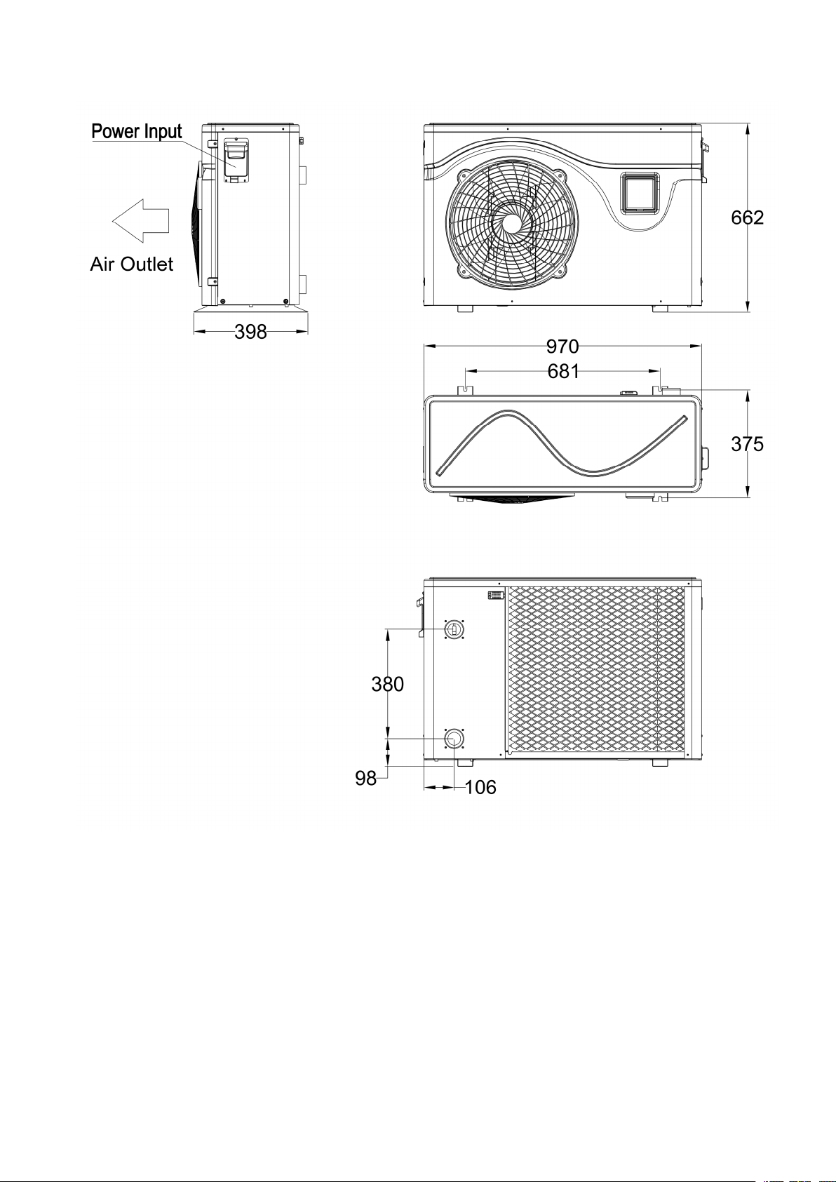
Net dimension LxWxH (mm) 970×398×662
Water pipe
Connection(mm)
Inlet 50
Outlet 50
Net weight (kg) 44 47 52
Noise level dB(A) 41~51 42~52 43~53
9
Model NE-F210SP/R4TINV-PA NE-F250SP/R4TINV-PA NE-F280SP/R4TINV-PA
Ambient Temperature: (DB/WB) 27°C/24.3°C; Water Inlet/Outlet Temperature: 26°C/28°C.
Heating capacity(kW)4.70~21.1 4.78~25.3 4.95~28.1
Power input (kW)0.33~3.59 0.33~4.36 0.35~5.1
COP 14.2~5.88 14.48~5.8 14~5.51
Boost
mode
Heating capacity(kW)21.1 25.3 28.1
COP 5.88 5.8 6.15
Smart
mode
Heating capacity(kW)17.1 20.36 22.61
COP 7.85 7.38 7.42
Silent
mode
Heating capacity(kW)10.3 12.53 13.91
COP 10.1 10.8 11.8
Ambient Temperature: (DB/WB) 15°C/12°C; Water Inlet Temperature: 26°C.
Heating capacity(kW)3.52~14.07 3.61~16.7 4.05~18.5
Power input (kW)0.460~2.865 0.476~3.394 0.537~3.737
COP 7.65~4.91 7.58~4.92 7.54~4.95
Boost
mode
Heating capacity(kW)14.07 16.7 18.5
COP 4.91 4.92 4.95
Smart
mode
Heating capacity(kW)11.13 13.21 14.63
COP 5.69 5.67 5.72
Silent
mode
Heating capacity(kW)7.09 8.41 9.31
COP 6.65 6.57 6.51
Ambient Temperature: (DB/WB) 35°C/-; Water Inlet/Outlet Temperature: 30°C/28°
Cooling capacity(kW) 4.32~10.36 4.52~12.29 4.61~13.61
Power input (kW)0.586~2.381 0.609~2.799 0.623~3.157
EER 7.37~4.35 7.42~4.39 7.39~4.31
Boost Mode
Cooling Capacity
(kW) 10.36 12.29 13.61
EER 4.35 4.39 4.31
Smart Mode
Cooling Capacity
(kW) 8.04 9.53 10.55
EER 5.26 5.28 5.36
Silent Mode
Cooling Capacity
(kW) 5.56 5.88 6.55
EER 6.55 6.45 6.41
Power supply 380-415V/3Ph/50Hz
Max power input(KW) 4.1 4.8 5.4
Max current(A) 7.3 8.6 10.2
Heating temperature range 15°C~40°C
Running temperature range -10°C~43°C
Advised swimming pool size 45m³~80m³ 55m³~90m³ 65m³~100m³
Refrigerant R32

10
Compressor MITSUBISHI ELECTRIC (DC inverter)
Air side heat exchanger Hydrophilic fin exchanger
Water side heat exchanger Titanium tube heat exchanger
Water flow(m³/h) 9.1 10.8 12
Water pressure drop (kPa) 32 35 38
Net dimension LxWxH (mm) 1100*455*773
Water pipe
connection(mm)
Inlet 50
Outlet 50
Net weight (kg)75 78 82
Noise level dB(A) 44~55 45~56 47~57
The technical specification of our heat pumps is provided for information purpose only. We reserve
the right to make change without notice in advance.
1. Noise at 1 m, at 4 m and at 10 m in accordance with Directives EN ISO 3741 and EN ISO 354
2. Calculate according to an in-ground private swimming pool covered with bubble
2. Unit Dimensions
Model: NE-F50SP/R4INV-PA , NE-F70SP/R4INV-PA, NE-F90SP/R4INV-PA
11
Model: NE-F110SP/R4INV-PA, NE-F150SP/R4INV-PA, NE-F180SP/R4INV-PA
12
Model: NE-F210SP/R4TINV-PA, NE-F250SP/R4TINV-PA, NE-F280SP/R4TINV-PA

13
3. Explosion View

14
1 Front plate 9 Framework 17 Right plate
2 Controller box 10 Compressor 18 Water flow switch
3 Fan motor cover 11 Middle plate 19 Evaporator
4 Fan 12 Four-way valve 20 Protection net
5 Motor 13 Throttle valve 21 Inverter PC board
6 Motor support 14 Titanium heat exchanger 22 Electrical box
7 Left plate 15 Handle 23 Top cover
8 Chassis component 16 Cable port
III. Installation Instructions
WARNING: Installation must be carried out by a qualified engineer.

15
This section is provided for information purpose only and must be checked and adapted if
necessary according to actual installation condition.
1. Pre-Requirements
Needed equipment for installation of heat pump:
Suitable power supply cable for unit’s power.
A by-pass kit and an assembly of PVC tube, stripper, PVC adhesive and sandpaper.
A set of wall plug and expansion screw.
We recommend to use flexible PVC pipe in order to reduce transmission of vibration.
Suitable fastening studs may be used to raise unit.
2. Location
Please comply with the following rules about heat pump location choosing.
1. The unit’s location must be convenient for operation and maintenance in the future.
2. It must be installed and fixed on flat concrete floor. The floor is stable to support the weight of the
unit.
3. A water drainage device must be provided close to the unit in order to protect the area where it is
installed.
4. If necessary, mounting pads could be used to support the weight of unit.
5. Confirm the unit is under well-ventilated condition; air outlet port is not facing to the windows of
nearby buildings and the outlet air can not be returned. In addition, provide enough space around the
unit for repair and maintenance.
6. The unit must not be installed in an area exposed to oil, flammable gases, corrosive products,
sulphurous compounds or close to high frequency equipment.
7. To prevent mud splashes, do not install the unit near road or track.
8. To avoid noise to neighbours, please make sure the unit is installed in less noise sensitivity area
or good sound isolation area.
9. Keep the unit as far as possible away from children.
10. Installation space
Unit: mm
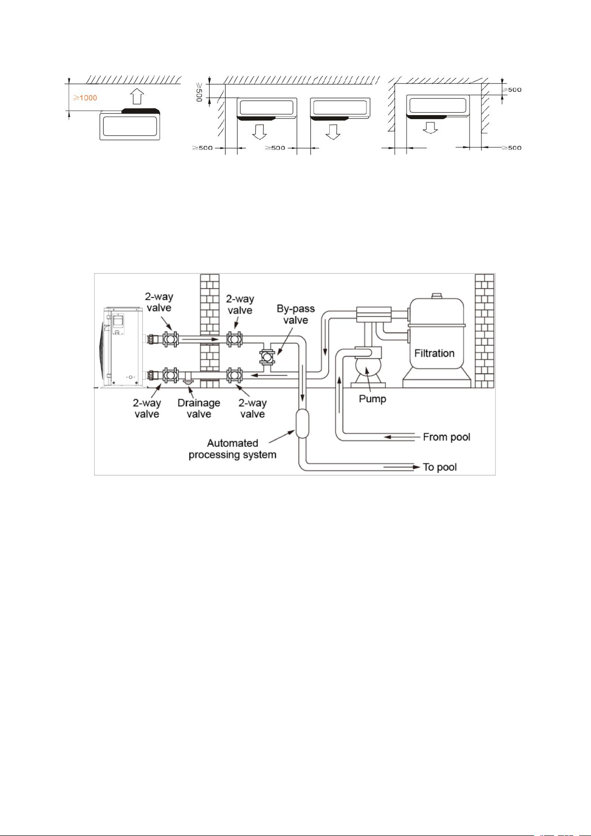
16
Anything could not be placed within at least 1m in front of heat pump.
Leave at least 500mm of empty space around the sides and rear of heat pump.
Do not put any stuff on or in front of heat pump!
3. Installation Layout
The heat pump is connected to a filtration circuit with a by-pass valve. The by-pass valve should be
half-opened (throttled), while all the other valves should be completely opened. We suggest to half
open by-pass valve to avoid excessive pressure on heat pump.
It is imperative that by-pass is placed after water pump and filtration. By-pass path usually consists of
3 valves. That makes it possible to adjust water flow which passes through heat pump and isolates
heat pump completely from any maintenance without affecting flow of filtration cycle.
The filter must be cleaned regularly to ensure that water in the system is clean and avoid blocking of
filter. It is necessary that drainage valve is fixed on the lower water pipe. If the unit is not running
during winter months, please disconnect power supply and let out drain water from unit through
drainage valve. If ambient temperature of running unit is below 0℃, please keep water pump
running.
4. Parallel Installation for 2 Units

17
5. Electrical Connection
Model
Power Supply Wires
Electricity Supply Cable Diameter Specification
NE-F50SP/R4INV-PA
220-240V/50Hz
3×2.5mm AWG 14
NE-F70SP/R4INV-PA 3×2.5mm AWG 14
NE-F90SP/R4INV-PA 3×2.5mm AWG 14
NE-F110SP/R4INV-PA 3×2.5mm AWG 14
NE-F150SP/R4INV-PA 3×2.5mm AWG 14
NE-F180SP/R4INV-PA 3×4.0mm AWG 12
NE-F210SP/R4TINV-PA
380-415V/3Ph/50Hz
3×4.0mm AWG 12
NE-F250SP/R4TINV-PA 3×4.0mm AWG 12
NE-F280SP/R4TINV-PA 3×4.0mm AWG 12
⚠WARNING: Power supply of heat pump must be disconnected before any operation.
Please comply with the following instruction to connect heat pump.
Step 1: Detach electrical side panel by a screwdriver to access electrical terminal block.
Step 2: Insert cable into heat pump unit port.
Step 3: Connect power supply cable to terminal block according to the diagram below.
NE-F50SP/R4INV-PA, NE-F70SP/R4INV-PA, NE-F90SP/R4INV-PA, NE-F110SP/R4INV-PA,
This manual suits for next models
2
Table of contents
Popular Inverter manuals by other brands

DUROMAX
DUROMAX XP12000EH user manual

Generac Power Systems
Generac Power Systems CorePower?/ES Generators Installation guidelines

Omron
Omron SYSDRIVE 3G3EV SERIES user manual

Goobay
Goobay 67922 user manual

Gentherm
Gentherm P-5050 operating manual

Hoymiles
Hoymiles HM-2000T-S Series Quick installation guide


GW Instek
GW Instek GFG-8020H user manual

socomec
socomec SUNSYS B15 Installation and operating manual

Triarchy Technologies
Triarchy Technologies VSG6G1C operating manual

Xantrex
Xantrex PROWATT SW SW 1000 owner's guide

Enerdrive
Enerdrive ePRO Combi owner's manual

Fuji Electric
Fuji Electric Frenic Mega Series user manual