Triarchy Technologies VSG6G1C User manual
9248 163 Street
Surrey, BC V4N 3C9
604-637-2167
Triarchy®VSG6G1C
USB Vector RF Signal Generator
Operating Manual
CW signal Analog modulation GMSK modulation 8PSK Pulse modulation
NB RF noise generator Frequency swee ing Ho ing with data Mod GSM signal 4FSK
Page 1 of 27

9248 163 Street
Surrey, BC V4N 3C9
604-637-2167
USB Vector RF S ectrum Analyzer O erating Manual
Copyright Notice
Copyright © 2018 Triarchy Technologies, Corp. All rights reserved.
Initial Version Dece ber 2018
Docu entation version 1.0
No part of this publication ay be reproduced, trans itted, transcribed, stored in a retrieval syste , or translated into
any language or co puter language, in any for or by any eans, electronic, echanical, agnetic, optical, che ical,
anual, or otherwise, without the prior written per ission of Triarchy Technologies, Corp.
Technical Support
For technical support, please call 1-604-637-2167, send e ail to [email protected] , or visit our website at
http://www.triarchytech.co
Page 2 of 27

9248 163 Street
Surrey, BC V4N 3C9
604-637-2167
Contents
1 Introduction 4
1.1 VSG6G1C Product Package Overview 4
1.2 USB Device Overview 4
1.3 TSG PC Application Overview 5
1.4 Electrical Require ents 6
1.5 Product internal Option unit 8
2 Getting Started 9
2.1 Install PC Application 9
2.2 Uninstall PC Application 10
2.3 First Working Exa ple 10
2.4 TSG Utility keys setting 10
3 O erations 12
3.1 Single frequency without Pulse odulation 12
3.2 Single frequency with Pulse odulation 13
3.3 Frequency Sweeping without Pulse Modulation 14
3.4 Frequency Sweeping with Pulse Modulation 14
3.5 Frequency hopping with/without Pulse Modulation 15
3.6 Analog Modulation 15
3.7 Digital Modulation with I&Q Engine 16
3.8 Phase Modulation with I&Q Engine 17
3.9 Exa ple for GSM signal output 18
3.10 Low Band 19
3.11 Pulse odulation signal output 21
3.12 Clock selection 21
3.13 I&Q sel 21
3.14 Hardcopy Operation 21
3.15 Off Line Operation 21
3.16 Flash OFF/ON Operation 22
4 I&Q Engine 22
4.1 I&Q Engine principle 22
4.2 I&Q file configuration 23
Page 3 of 27

9248 163 Street
Surrey, BC V4N 3C9
604-637-2167
1 Introduction
VSG6G1C is USB RF signal generator, it plug on PC and working with PC application, then VSG6G1C will be really
RF signal generator, the RF frequency range fro 100Hz to 6.1GHz for VSG6G1C odel, A plitude output range
will be -100dB ~10dB . VSG6G1C are will very easy to use, PC application window just like front panel of
nor al desktop signal generator. If PC support touch screen, operating VSG6G1C are very si ilar to operate
desk top signal generator.
VSG6G1C have ore functions. It also can generate a lot of odulation signal with I&Q engine and Pulse
odulation. So that it can si ulate a lot of wireless syste .
1.1 VSG6G1C Product Package Overview
VSG6G1C product package will be:
1: USB signal generator device (25x25x100 ) one piece
2: USB Type C cable one piece
3: SMA to MMCX cable one piece
4: N to SMA adapter one piece
5: CD with PC application progra and docu ent one piece
6: 160x110x40 product case one piece
1.2 USB Device Overview
1: RF output N connector (fe ale) RF signal output
2: USB connector USB Type C connector interface with PC
3: IP MMCX connector I port positive Output/Input
4: IN MMCX connector I port negative Output/Input
5: QP MMCX connector Q port positive Output/Input
6: QP MMCX connector Q port negative Output/Input
7: Clock MMCX connector Clock Output/Input
8: Pulse MMCX connector Pulse signal Output
Page 4 of 27
9248 163 Street
Surrey, BC V4N 3C9
604-637-2167
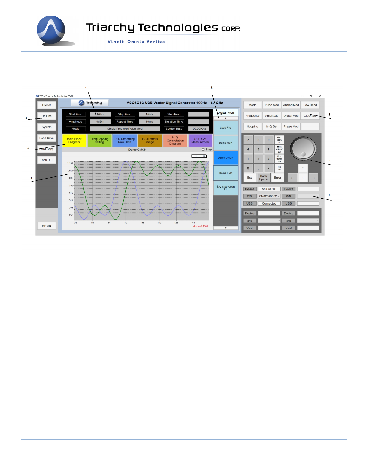
1.3 TSG PC Application Overview
1: utility keys
Allows user to access the syste level function, Function detail will be shown on second function keys
2: Message selection keys
Click the Message selection key, the Message display area will be followed to be changed.
3: Message dis lay area
Message display area will be shown the detail infor ation of output signal.
Main Block Diagram is shown the how the RF vector signal generator working, how the signal output.
Freq Ho ing setting will be table of hopping frequency points.
I&Q Streaming Raw Data is wavefor of I&Q raw data, it will be sa e as real wavefor signal fro I&Q
port.
I&Q attern image is shown I&Q pattern if I&Q raw data is generated based on the I&Q pattern.
I&Q constellation diagram is shown, it will be selected to depended on Raw data or I&Q pattern.
4: Status block
Status block will be shown the ain para eter of output signal, such as frequency, a plitude, duty
cycle, sy bol rate and working ode. Detail the infor ation of output signal is also shown on Message
display area. (Please note: para eter can not set up fro Status block, it is only display window)
5: Second functions keys
Second function keys will be extend key, it will be followed the function keys and utility key to extend
function setting to ore detail. It is si ilar to soft key in ost of equip ent which is location on side of
screen. Most of para eter will be input fro second function keys.
6: Function keys
Page 5 of 27
9248 163 Street
Surrey, BC V4N 3C9
604-637-2167
Most of ajor the equip ent setting will be done by Function keys. General setting for signal generator
will be:
Select ode, such as frequency selection for single, sweeping and hopping and pulse odulation
selection.
Input frequency, such as setting for signal frequency, frequency sweeping and frequency hopping
Input a plitude, such as level setting.
Input ti ing for pulse odulation.
Adding I&Q odulation, to setup a lot of different kind of odulation to eet each application
require ents.
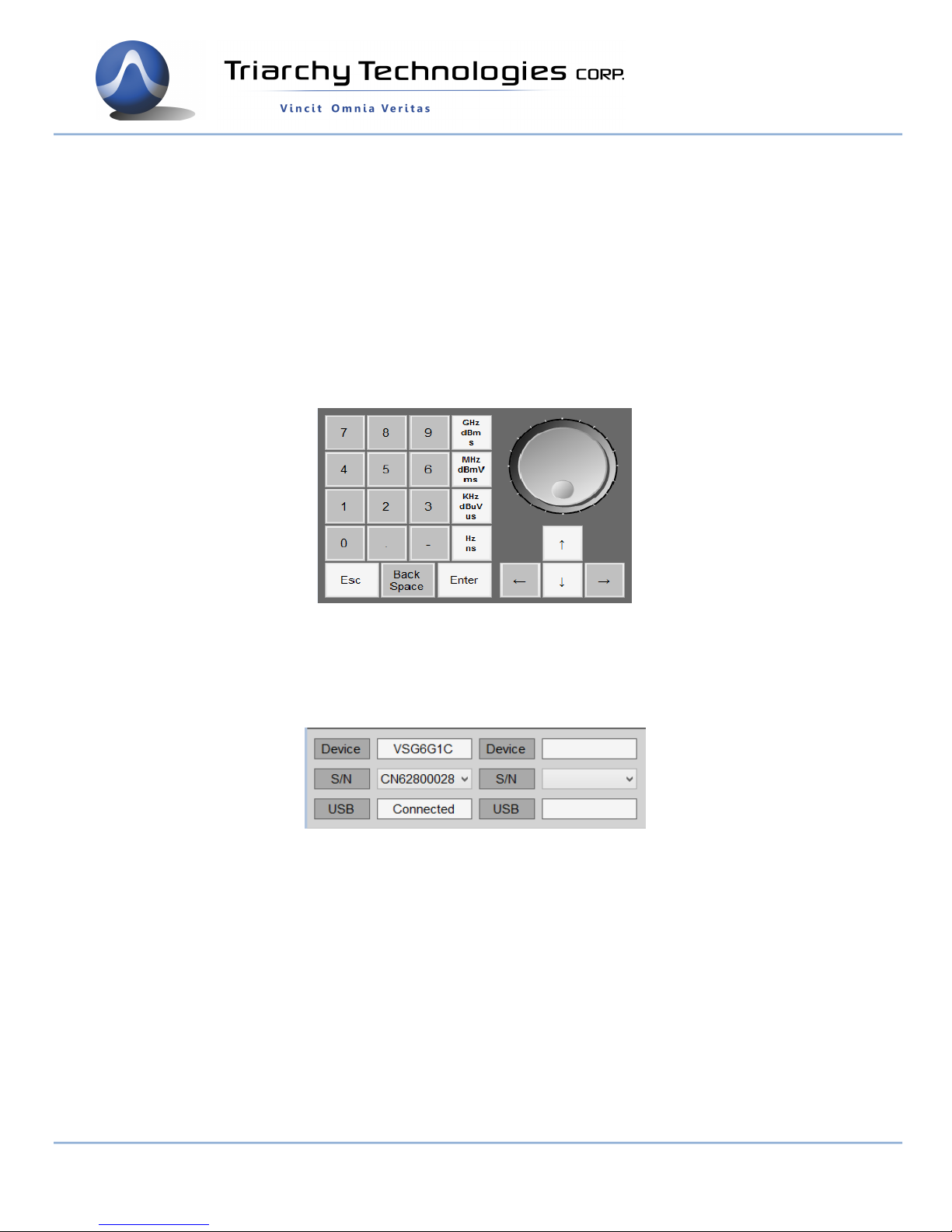
7: Digital in ut keys
Digital input keys will input digital and units for frequency, a plitude and ti ing. When units key is
clicked, the co end is sending to USB dongle. This standalone input key is si ilar to desktop
equip ent. It will be better to be used in touch screen PC without keypad.
8: USB connection area
When USB device plug in the PC, USB connection area will be shown the product odel na e, S/N and
connection status. When connected is shown, the device is really connected to TSG application, TSG will
fully control the USB device.
1.4 Electrical Require ents
1.4.1 S ecification for Frequency
Frequency range for VSG6G1C:
Band 1 : 1MHz ~4000MHz
Band 2: 4000MHz ~6100MHz
Low Band : 100Hz ~1MHz
Frequency resolution: 1 Hz
Frequency stability: +/-0.5PPM over te perature -20~+60 degree
Frequency aging per year: +/-1PPM
Frequency reference output: 10MHz
Frequency reference input: 20MHz
Page 6 of 27

9248 163 Street
Surrey, BC V4N 3C9
604-637-2167
1.4.2 S ecification for ower
Output level range for VSG6G1C :
Band 1: -100dB ~10dB (Calibrated )
Band 2: -100dB ~0dB (Calibrated)
Low band : -50dB ~0dB (No calibrated)
Output level resolution: 0.25dB
Output level error: <1dB (@ 1GHz at 25C)
1.4.3 S ecification for Pulse modulation
Pulse repeat ti e with single frequency: 40uS to 20s
Pulse repeat ti e with Sweeping and hopping: 400uS to 20s
Pulse duration ti e: 0.25us to 5S
Multiple pulse nu ber: 2~250
Multiple pulse delay: 0.71us~5s (last pulse cannot be overlay with first pulse)
On/off ratio: >90dB
1.4.4 S ecification for Frequency swee ing with/ without ulse modulation
Span range: 50 Hz to full span
Scan points range: 2 to 50000
Frequency step range: 1 Hz to 1GHz
Step ti e: Controlled by pulse repeat ti e 400uS to 20s
Pulse width in Pulse ode: Controlled by pulse duration ti e 0.25us to 10s
* If it is in “Freq sweeping w/o Pulse od”, this para eter is no function
1.4.5 S ecification for Frequency ho ing with/ without ulse modulation
Frequency hopping range: 50Hz to 6.1GHz
Frequency hopping nu ber: 2~4000
Frequency hopping ti es: 2500 hop/s to 0.05 hop/s
Pulse width in hopping ode: Controlled by pulse width ti e 0.25us to 5s
* If it is in “Freq hopping w/o pulse od”, this para eter is no function
1.4.6 S ecification for I&Q unit for analog modulation
FM odulation in De o key: Modulation frequency range: 10Hz to 2KHz;
Modulation index 20
AM odulation in De o key: Modulation frequency range: 10Hz to 2KHz;
Modulation index 80%
PM odulation in De o key: Modulation frequency range: 10Hz to 2 KHz;
Modulation index 280 degrees
*Define the I&Q RAW data file, any kind of analog odulation can be achieved. Such as RF narrow band noise
signal.
1.4.7 S ecification for I&Q unit for Digital modulation
MSK odulation in De o key: Data rate rage: 20b/s to 200Kb/s;
GMSK odulation in De o key: Data rate rage: 20b/s to 200Kb/s; BT=0.7
FSK odulation in De o key: Data rate rage: 10b/s to 10Kb/s;
* Define the I&Q data file, study different I&Q pattern, internal I&Q engine will generate the ost of digital
odulation; Such as SFSK.
1.4.8 S ecification for I&Q unit for hase modulation
QPSK odulation in De o key: Data rate rage: 200b/s to 2Mb/s;
8PSK odulation in De o key: Data rate rage: 400b/s to 4Mb/s;
Page 7 of 27

9248 163 Street
Surrey, BC V4N 3C9
604-637-2167
16QAM odulation in De o key: Data rate rage: 800b/s to 8Mb/s;
* Define the I&Q data file, study different I&Q pattern, internal I&Q engine will generate the ost of digital
odulation.
1.4.9 S ecification for I&Q internal modulation
I&Q sa ple rate: 2KHz~2.4MHz (I&Q step count fro 36000~30)
note: ti er clock is 72MHz, sa ple rate=ti er clock/step count
I&Q data buffer size: 100KB
1.4.10 S ecification for I&Q external modulation
Baseband signal bandwidth: 500MHz
I&Q signal level: 0.9Vpp
I&Q reference points: 0.5V
*internal I&Q odulation IC is ADRF6755, please check ADRF6755 data sheet for detail interface.
1.4.11 S ecification for Low band mode
SIN Wavefor : 100Hz~1MHz
This is SW DDS, output fro N connector. DDS clock is 2MHz, so that
ore distortion of SIN wavefor will be occurred fro 300KHz ~1MHz.
Load Mod File: I&Q file will be working with Low band SIN wavefor to generate any
kind of odulation
the I*Q file can be generated fro I&Q engine, but keep two rule:
1: I&Q clock keep at 2MHz ( step count is 36)
2: sy bol rate ust be low than frequency of low band SIN wavefor .
Load Raw file: Generate wavefor based on the I&Q buffer file. It is Arbitrary
wavefor generator with clock 2MHz.
More useful can be generated in this ode such as, DTMF, stereo FM
signal for at.
AM FM PM Mod: To odulated Low band signal (fro SIN wavefor , odulated or
Arbitrary wavefor ) to RF band, to generated AM, FM and PM of RF
signal
AM index: 0~100%
FM index: 1Hz~500KHz
PM index: -18000degree~+18000 degree
note: Low band output fro N connector after SIN wavefor , Load Mod file, Load Raw file setting.
RF signal signal will be output fro N connector after AM FM PM od setting.
1.4.12 S ecification for Pulse signal out ut
Pulse output level: 3.3V
Pulse repeat ti e: 40uS to 20s
Pulse duration ti e: 0.25us to 5S
Multiple pulse nu ber: 2~250
Multiple pulse delay: 0.71us~5s (last pulse cannot be overlay with first pulse)
the output will be fro “pulse” MMCX connector at rear panel.
1.5 Product internal Option unit
The product internal option will be:
A: High speed I&Q data generator:
Page 8 of 27

9248 163 Street
Surrey, BC V4N 3C9
604-637-2167
it can generator up to 100MHz/B data rate I&Q signal, so that it can si ulate high speed wireless syste , such
as wifi, LTE, icrowave relay syste .
2 Getting Started
2.1 Install PC Application
Open the CD, go into the SW file folder, you can find setup.exe and Docu ent folder, please double click to
setup.exe to start the installation.
When you finished the installation, the TSG ICON will be shown on the desk. Double click the TSA ICON.
After installation, the progra file will be installed at progra file folder.
C:\Progra Files (x86)\Triarchy Tech\TSG Signal Generator
The application data will be generated at Docu ent folder:
C:\Users\Userna e\Docu ents\Triarchy Tech\Signal Generator
Custo er need to check the application data at docu ent folder.
Hardcopy folder will be stored the i age file which generated by hardcopy key.
Hopping folder will be stored the hopping files.
IQ Modulation folder will be stored the all the odulation file.
Setting folder will be stored the saving file, preset, and special setting can be stored in it, then using load key to
resu ed the special setting.
Page 9 of 27

9248 163 Street
Surrey, BC V4N 3C9
604-637-2167
The custo er can add ore files into docu ent folder, so that ore odulation signal can be generated.
2.2 Uninstall PC Application
Try to find Uninstall TSG ICON, then click it to uninstall.
You also can use control panel to uninstall the TSG progra .
2.3 First Working Exa ple
When you first ti e to use the VSG6G1C product, you shall turn off the TSG PC application. Connecting
VSG6G1C to PC via USB cable, PC will install the USB hardware configuration with a little long ti e, please wait
for all the configuration is installed.
Then open the TSG PC application, the USB connection area will be shown the device odel, S/N and
connection status.
Connect device output to Spectru analyzer. Then click RF off, RF output will be on.
Spectru analyzer will be shown the signal wavefor :
CW Signal out ut at 1GHz and 0dBm level
2.4 TSG Utility keys setting
Preset
Page 10 of 27

9248 163 Street
Surrey, BC V4N 3C9
604-637-2167
When clicking the Preset key, the second function key will be shown:
Last_setting key select to ON, when TSG progra turn on or USB device plug off and on, all syste
setting will go to last setting.
Last_setting key select to OFF, when TSG progra turn on or USB device plug off and on, all syste
setting will go to preset 1 status.
Preset x (x=1~6) can be clicked, then syste setting will go into the preset x status.
Preset x can be setup at Load Save key
Preset 1 is stored the default setting
Off Line
offline Off, offline function is not working
offline ON, USB device will be working at any 5V power source based on the offline setting to work.
Save Files, setup specific signal by setting function key. Then save this setting into file. More signal
setting can be saved by repeating save setting.
Load Files, load file to set the offline function.
Interval On, Interval Off and Loop will be used to setup duration and period of offline signal.
System
When clicking the Syste key, the second function key will shown:
Manual AMP Cal:
The value can be input, when input ter inal attached the attenuator or cable will be caused path loss.
Manual AMP cal range is -10dB~+10dB
Manual Freq Cal:
This function is used for co pensate of I&Q error in RF path to i prove the EVM perfor ance.
Application note will discuss this ite ore detail. Manual Freq Cal range is +/- 50KHz
Send Cal File to Dongle:
This function is reserved for anufacture using.
Change the dongle series number:
It need passwords to change the series nu ber. This function is reserved for anufacture using.
Version:
Show the current TSG version nu ber
Load Save:
When clicking the Syste key, the second function key will shown:
Save Setting:
To save the current setting status into file, it can be resu e setting by Load setting.
If save the file into preset folder, and na e as Presetx, the preset set can be updated by save setting
key.
Load Setting:
To recall the setting file by Load setting, the old setting status will be represent into current setting.
Hardco y
Click hard copy, the i age of setting will be save at docu ent folder.
Flash ON/OFF
when Off Line is OFF, Flash On is working as last setting offline function, set Flash ON and RF ON, (Off
Line is off), the signal status will stored in USB device, last signal status will be working at any 5V source
power.
RF ON/OFF
This is selection key, the Preset 1 will set this key to RF OFF, after you connect RF output ter inal with
UUT, then you can set this key to RF ON.
Page 11 of 27

9248 163 Street
Surrey, BC V4N 3C9
604-637-2167
3 O erations
3.1 Single frequency without Pulse odulation
Select Mode to “Single Freq without Pulse Mod”. Click RF OFF to turn on the RF output, input frequency and a plitude
value fro Frequency and a plitude function key.
Set VSG6G1C a plitude level to 0dB at 1GHz. set RSA306 Span to 1MHz and 5MHz, RBW to 1KHz, to get spectru
wavefor .
CW Signal out ut at 1GHz and 0dBm level CW Signal out ut at 1GHz and 0dBm level
VSG6G1C a plitude level can be set to -100dB , and a plitude setting resolution is 0.25dB So that VSG6G1 can be used
to easure receiver sensitivity level.
VSG6G1C RF frequency range fro 1MHz to 6100MHz, and frequency setting resolution is 1Hz, the following i age are
shown -100dB level and 6Ghz frequency output.
CW Signal out ut at 1GHz and -100dBm level CW Signal out ut at 6GHz and 0dBm level
Page 12 of 27
9248 163 Street
Surrey, BC V4N 3C9
604-637-2167
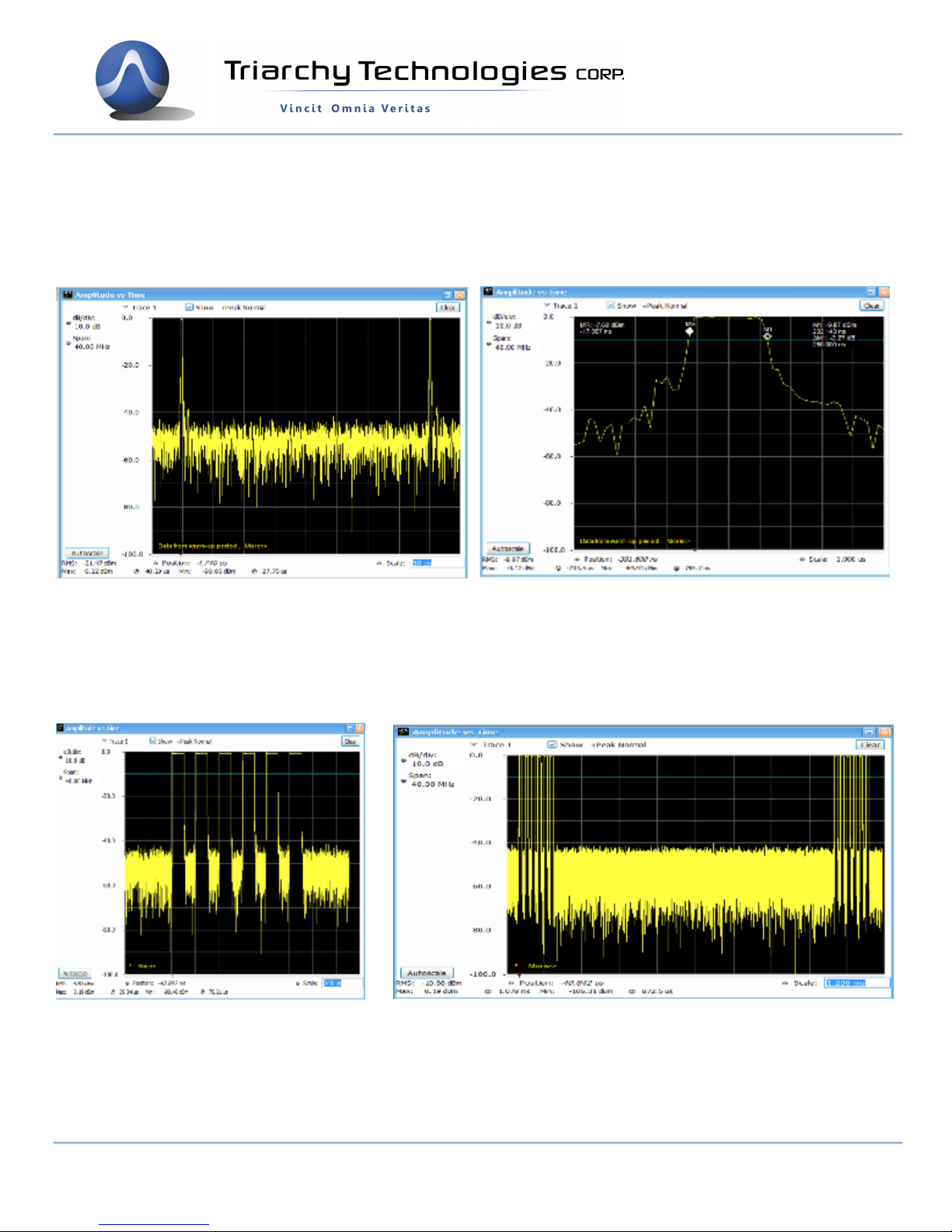
3.2 Single frequency with Pulse odulation
Select Mode to “Single Freq with Pulse Modulation”. Pulse odulation in signal frequency can be achieved narrow pulse
odulation, the ini u pulse width will be 0.25us, it can be used to si ulate the radar signal and so e detection device
signal. The following i age are shown pulse odulation signal with 0.25us pulse width, and 40us period.
Pulse modulation out ut at 1GHz with 0.25us on 39.75us off Pulse modulation out ut at 0.25us width wide
The pulse odulation have ultiple pulse function, the ultiple pulse nu ber can be fro 2~250, so e
transponder have ultiple pulse signal for at, and ultiple pulse working as data infor ation. The following
i age is shown the ultiple pulse odulation with 1us pulse width and 6 pulse group.
S ectrum from RSA306 RF time waveform from RSA306
When VSG6G1C is working at pulse odulation ode, it can open the I&Q odulation to add data into pulse signal, it can
si ulation physical layer data fra e of co unication set, such as GSM, wireless key.
Page 13 of 27
9248 163 Street
Surrey, BC V4N 3C9
604-637-2167
3.3 Frequency Sweeping without Pulse Modulation
Select Mode to “Freq Sweeping without Pulse Modulation”. click frequency then setup frequency at second function area. Input
Start frequency, stop frequency and step frequency for frequency sweeping setting, then click the Send to dongle. The USB dongle
will be followed to setting to work.
The step frequency is fro 1Hz to 1GHz, so that the span of sweeping can be s all step or large step.
The sweeping ti ing will be follow Pulse Mod function. The pulse period will be one step frequency. The ini u pulse period ti e
is 400us, but RF signal will be ute by 300us for frequency setup ti e.
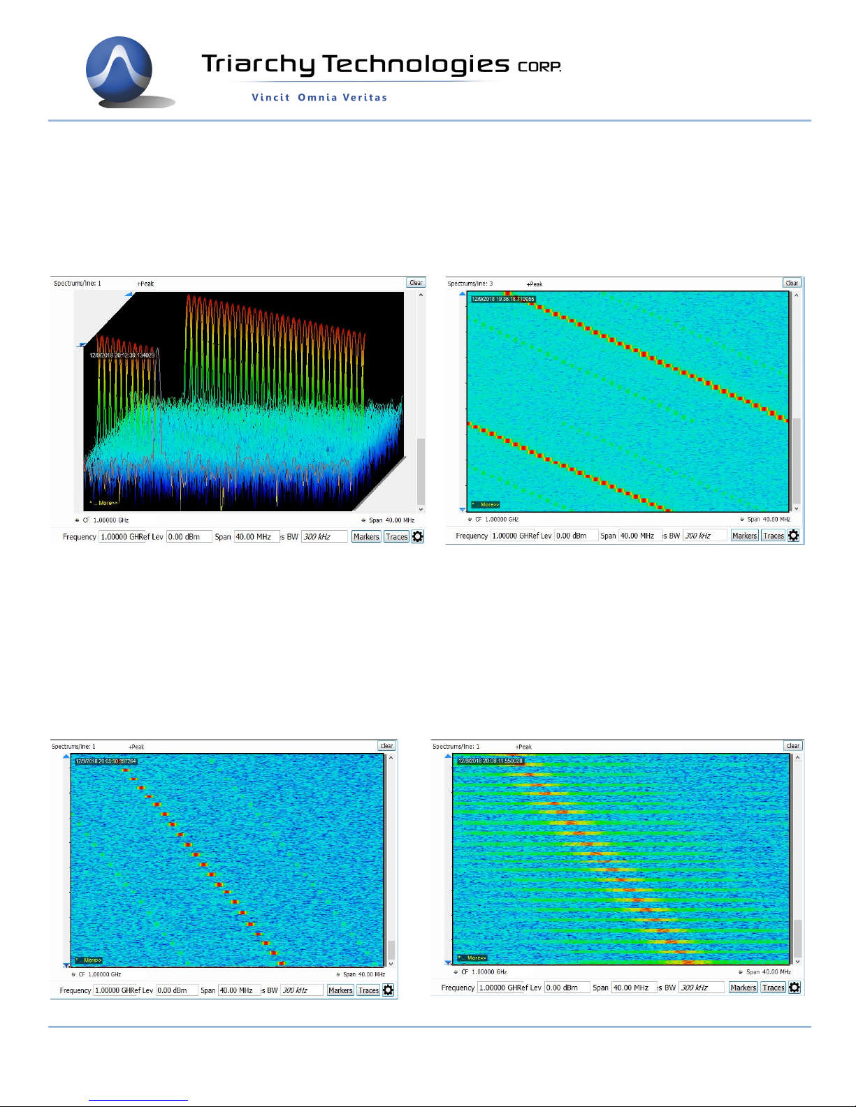
Frequency Sweeping 3D dispaly Frequency Sweeping 2D display
3.4 Frequency Sweeping with Pulse Modulation
Select Mode to “Freq Sweeping with Pulse Modulation”. It need to setup pulse odulation para eter at “Pulse Mod” function key.
It still can add I&Q odulation into the frequency sweeping ode ( both with/without odulation), just set I&Q Sel into internal,
then select I&Q file at Analog/Digital/Phase od functional key. The following i age is shown that frequency sweeping
with/without I&Q odulation at waterfall display.
Frequency Swee ing with ulse modulation Frequency Swee ing with ulse and I&Q modulation
Page 14 of 27
9248 163 Street
Surrey, BC V4N 3C9
604-637-2167
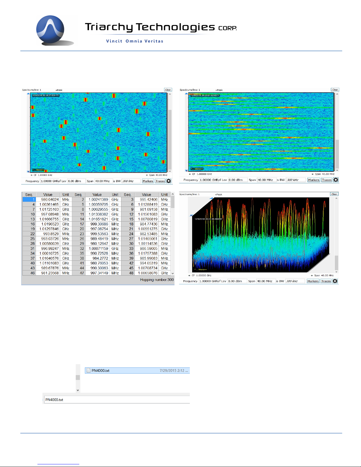
3.5 Frequency hopping with/without Pulse Modulation
Select Mode to “Freq Hopping with/without Pulse Modulation”, then click Hopping function key, it need to load file or
select De o key. De o1 is 300 points hopping and frequency range fro 980MHz~1200MHz. It also need to setup “Pulse
Mod” key to setup hopping ti ing para eter. The fast hopping rate is 2500 hopping/s.
Frequency ho ing without ulse modulation Frequency ho ing with ulse and I&Q modulation
Frequency table of ho ing Frequency ho ing 3D dis lay
3.6 Analog Modulation
First, “I&Q Sel” key shall be at Internal, then I&Q odulation can be working. Select “Analog Mod” go into Analog
odulation.
Analog odulation is using I&Q raw data file. AM/FM/PM odulation index can be changed by using these raw data files,
signal repeat frequency can be changed by setting the I&Q step count and I&Q data a ount. It also can generate a lot of
odulation signal by working on the different raw data file.
Following exa ple is narrow band RF noise signal. I&Q will be rando noise data, I&Q clock will be 2MHz, so that 2MHz
bandwidth noise will at 1GHz.
When signal level set to -90~-100dB , this device can be si ulated noise generator.
RF narrow band noise is generated at 1GHz.
Page 15 of 27
9248 163 Street
Surrey, BC V4N 3C9
604-637-2167
S ectrum from RSA306 I&Q Raw data from TSG I&Q constellation from TSG
There are de o AM, FM and FM key in the second function of Analog Mod , just click it, then AM/FM/PM signal will be
generated fro N connector.
De o AM index is 80%
De o FM index is 20, if odulation frequency is 2K, deviation will be 40K
De o PM index is 280 degree
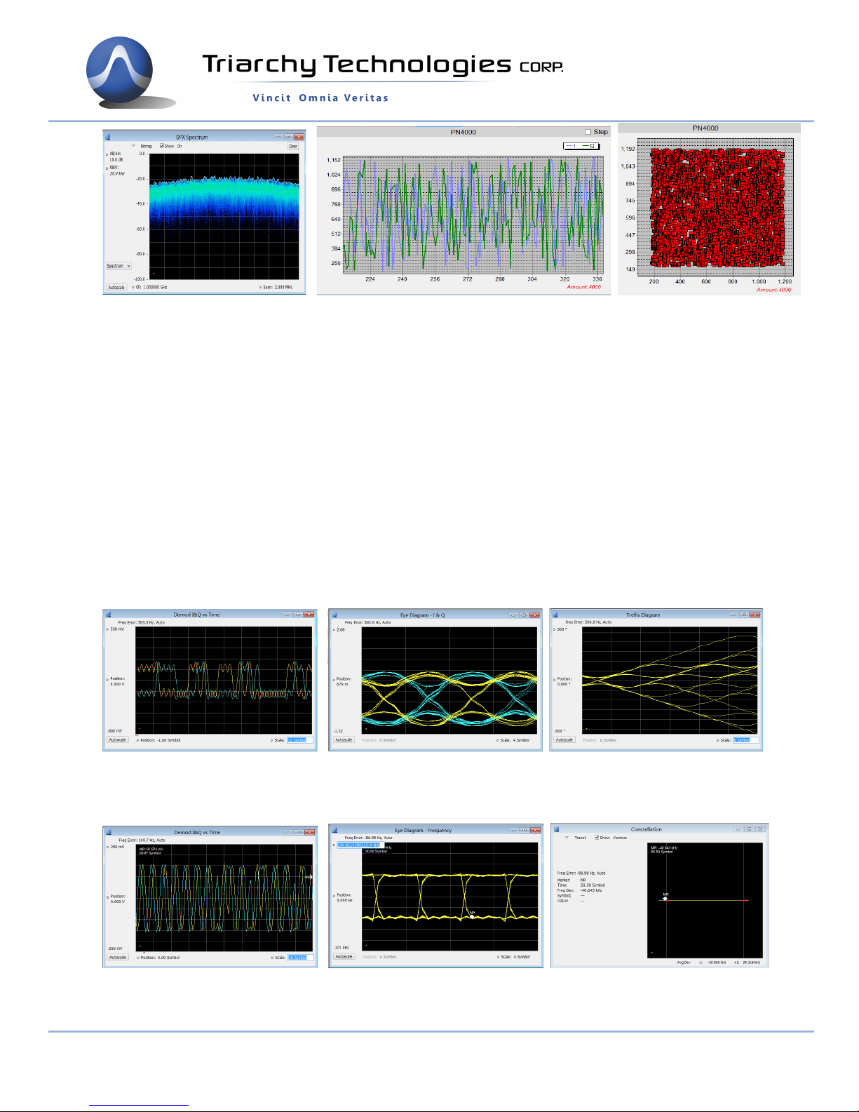
3.7 Digital Modulation with I&Q Engine
First, “I&Q Sel” key shall be at Internal, then I&Q odulation can be working. Select “Digital Mod” go into digital odulation.
There three de o in the Digital Mod second function area, they are MSK, GMSK and FSK. The data rate can be changed by setting
I&Q step count.
More odulation signal can be archived by loading file.
GMSK signal can be generated by clicking Do e GMSK.
GMSK data rate will be 100KHz/b when step count is 72, changing I&Q step count will change GMSK data rate.
Demod I&Q vs Time from RSA306 Eye Diagram from RSA306 Trellis Diagram from RSA306
FSK signal can be generated by clicking Do e FSK.
FSK data rate will be 40KHz/b when step count is 50, changing I&Q step count will change FSK data rate.
Demod I&Q vs Time from RSA306 Eye Diagram from RSA306 Constellation Diagram from RSA306
Page 16 of 27

9248 163 Street
Surrey, BC V4N 3C9
604-637-2167
Working on I&Q file,ost of all digital odulation can be generated, save the I&Q file into Digital odulation sub
folder, The 4FSK file can be found at 4FSK folder. Load IQ 4FSK_1.txt file, 4FSK signal can be generated
4FSK data rate will be 40KHz/b, changing I&Q step count will change 4FSK data rate.
I&Q attern from TSG Eye Diagram from RSA306 Constellation Diagram from RSA306
3.8 Phase Modulation with I&Q Engine
First, “I&Q Sel” key shall be at Internal, then I&Q odulation can be working. Select “Phase Mod” go into phase odulation.
There three de o in the Digital Mod second function area, they are QPSK, 8PSK and 16QAM. The data rate can be changed by
setting I&Q step count.
More odulation signal can be archived by loading file.
QPSK signal can be generated by clicking Do e QPSK.
QPSK data rate will be 4MHz/b, changing I&Q step count will change QPSK data rate.
Constellation Diagram from TSG Eye Diagram from RSA306 Constellation Diagram from RSA306
8PSK signal can be generated by clicking Do e 8PSK.
8PSK data rate will be 8MHz/b, changing I&Q step count will change QPSK data rate.
Constellation Diagram from TSG Eye Diagram from RSA306 Constellation Diagram from RSA306
16QAM signal can be generated by clicking Do e 16QAM.
16QAM data rate will be 16MHz/b, changing I&Q step count will change QPSK data rate.
Page 17 of 27
9248 163 Street
Surrey, BC V4N 3C9
604-637-2167
Constellation Diagram from TSG Eye Diagram from RSA306 Constellation Diagram from RSA306
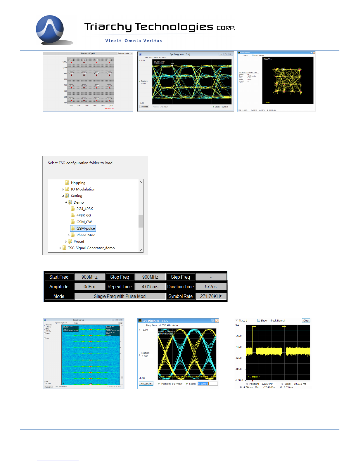
3.9 Exa ple for GSM signal output
load I&Q file fro Load Save key. More co plex signal can be setting by using different function keys. After signal is generated,
Using Save key to save the setting status, the Load function can resu e the signal which setup before.
Select GSM ulse signal from Setting /Demo folder
Status block will be:
GSM data rate will be 271Kb with GMSK odulation, repeat ti e will be 4.6 s, duration ti e will be 577us.
GSM signal with I@Q Mod 271K GMSK signal two ulse of GSM signal
3.10 Low Band
Page 18 of 27
9248 163 Street
Surrey, BC V4N 3C9
604-637-2167
when Low band select to ON, N connector channel switch fro RF channel to I&Q DAC channel. DAC channel will be directly output
to N connector, it can generate 100Hz to 1MHz signal.
The Low band output is really SW DDS, it eans that I&Q file will be calculated by SW based on the input value, then DAC will be
converted I&Q file into real signal. The DDS clock is 2MHz, so that it can only generate axi u 1MHz signal, but when frequency
larger than 300KHz, SIN wavefor distortion will be larger.
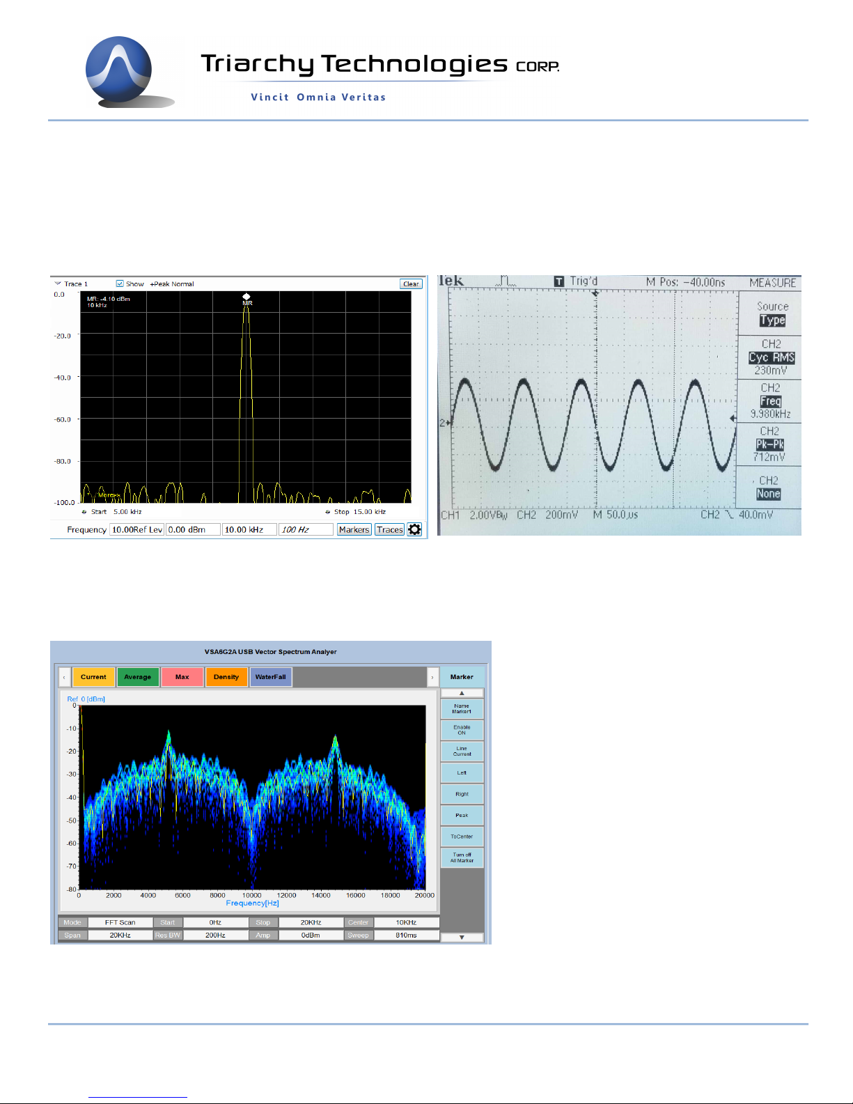
When select Wave_Sin, just input frequency value, after I&Q data is generated, the low frequency will be generated at N
connector. The a plitude level will be fro -50dB ~0dB , it is not calibrated. It can be setup at “A plitude” Key.
S ectrum waveform of Low Band 10KHz signal out ut Time domain waveform of Low Band 10KHz signal out ut
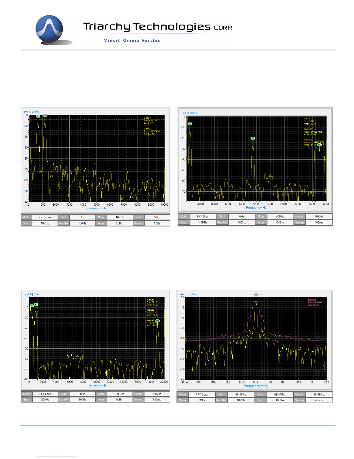
when Click “Load Mod File” key in low band, it will load I&Q file to generate odulation signal based on low band
frequency which generated at “Wave_Sin”. So exa ple, if 10KHz Sin wavefor is generated by “Wave_Sin” key, load 4.8K/b
FSK I&Q file at “Load Mod File” key. The output signal will be 10KHz signal with 4.8K/b FSK odulation, two FSK frequency
will be 5.8KHz and 14.8KHz.
4.8K/b FSK signal base on 10KHz carrier
Changing the I&Q file, the ore odulation signal can be get, such as MSK, BPSK, 4PSK .....
Page 19 of 27
9248 163 Street
Surrey, BC V4N 3C9
604-637-2167
When click the “Load Raw File” key in low band, arbitrary signal wavefor be archived based the data in the file. Several
wavefor can be co bined together, the Co bined action could be (+),(-),(*),(/), or so e kind of odulation.
There DTMF signal file can be found at Low band/Raw File folder. It is dual tune signal which used for telephone keypad.
Another wavefor in the Load band/Raw File folder is FM Stereo base band signal, Stereo signal need to co bine L and R
signal onto one FM odulation signal. It has one pilot signal fp, fp is 19KHz, so that (L-R) will be odulated to 38KHz.
The FM stereo signal for ula will be:
(0.9*((L+R)/2+SIN(4*PI()*fp*T)*(L-R)/2)+0.1*SIN(2*PI()*fp*t))*75KHz(FM)
the Raw data file can co bine with 1) L+R signal, 2) (L-R) section odulated to 38KHz, 3)19KHz pilot signal.
DFMF dual tone signal, 697Hz and 1209Hz FM stereo base band signal, (L+R), ilot and modulated (L-R)
When click the “AM FM PM Mod” key in low band, Input index of AM/FM/PM, then click Set AM/FM/PM. The low band
signal will be odulated into RF signal, N connector output will be switch back to RF channel. RF frequency and a plitude
level are setting by “Frequency” key and “A plitude” key.
it will be easy to generate AM/FM/PM with single odulated frequency and not need to handle I&Q file, just need to input
low band frequency and index.
If odulated low band signal is fro “Load Raw File” , the ore co plex low band signal can be generated, then odulated
it into RF signal. Stereo FM signal is one exa ple, after load FM stereo base band signal, and set RF frequency to FM radio
channel, such as 88.9MHz, the FM radio can be received this RF signal, and play dual tone to each speaker.
FM stereo base band signal, L+R and ilot FM stereo RF signal, frequency=88.9MHz
Page 20 of 27
Table of contents
Other Triarchy Technologies Inverter manuals

Popular Inverter manuals by other brands


TECO
TECO A510 quick start guide

CE+T Power
CE+T Power TSI MEDIA 2I user manual

TOMMATECH
TOMMATECH Trio-Plus Series user manual

Grundfos
Grundfos CUE instructions

Motomaster
Motomaster ELIMINATOR 011-2047-2 instruction manual

CHAFFOTEAUX
CHAFFOTEAUX Zelios CF 2.0-1 RF Instruction manual for authorized service personnel


