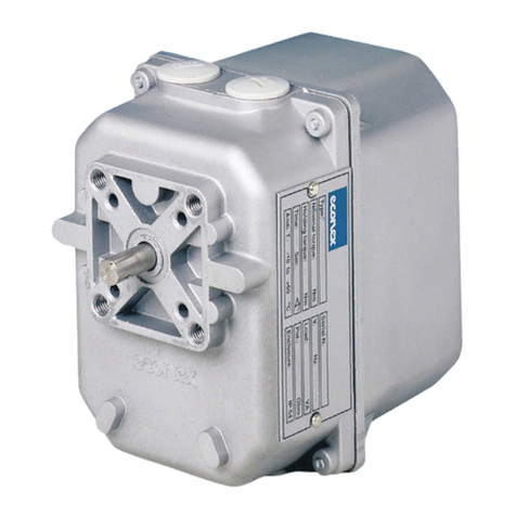
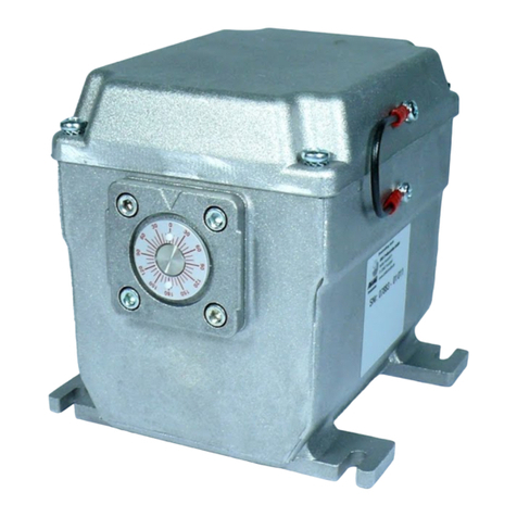
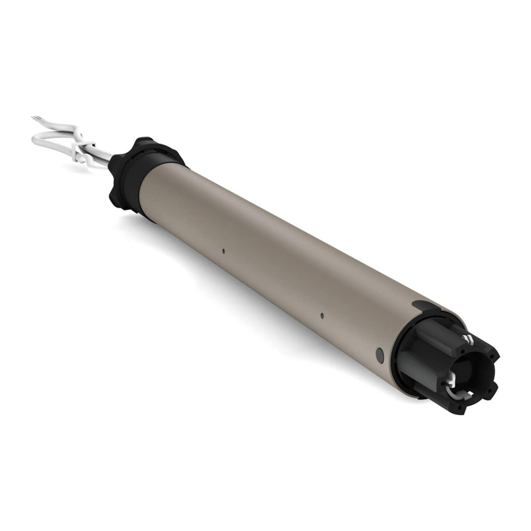
Econex AB1 SE Series User manual

ELECTRONIC ROTARY GEAR MOTOR
SERIES AB1...SE
INSTALLATION AND
OPERATING INSTRUCTIONS
1GENERAL FEATURES 2
2TECHNICAL DATA 2
3INSTALLATION 3
4WIRING 4
5CABLE CONNECTIONS 5
5.1 TERMINAL BOARD 5
5.2 AUXILIARY MICROSWITCHES 5
5.3 OPTIONAL POTENTIOMETER FOR ANSWER SIGNAL OF POT.BPOSITION 5
6AUXILIARY MICROSWITCHES 5
7FEEDBACK POTENTIOMETER/S6
8CONTROL STATION 6
9ADJUSTMENTS 7
9.1 ENDSWITCHES 7
9.2 ELECTRONIC BOARD [ONLY ON EMERGENCY]8
10 OPERATING 8
11 MAINTENANCE 8
12 REPLACEMENT 9
13 ELECTRONIC CONFIGURATION 9
13.1 ELECTRONIC CONFIGURATION
AB1…SE2 INPUT SIGNAL 4-20 MAOR 0-10V OUTPUT SIGNAL 0-10V 10
13.2 ELECTRONIC CONFIGURATION
AB1…SE4 INPUT SIGNAL 0-10V 11
13.3 ELECTRONIC CONFIGURATION
AB1…SE5 INPUT SIGNAL 4-20 MA12

AB1…SE instructions 2 of 12
Form 140516
1 GENERAL FEATURES
Electronic rotary gear motors of series AB1...SE have been newly conceived and specially
designed to be installed on residential and industrial combustion systems.
They are particularly suitable for control and regulation of modulating disc valves, butterfly
valves, dampers and other fluid regulation systems requiring control of position angle
within 90°. Electronic rotary gear motors are unipolar and bidirectional with high static and
maintaing torque. Analogic input signal according to current [4 ÷ 20 mA] or voltage change
[0 ÷ 10 Vdc].
WARNING
Installation, wiring, adjustment and maintenance of gear motors must be carried out
exclusively by skilled and authorized service technicians. Non-proper installation,
adjustment, modifications, use and maintenance may cause injuries to the staff or material
damages. It is therefore necessary to respect strictly the following instructions and local
prescriptions for the installation of electronic devices.
2 TECHNICAL DATA
Body and cover die-cast aluminium
Nominal torque 3 ÷ 5 Nm
Maintaining torque 2,5 ÷ 3 Nm
Rotation time 15 ÷ 60 seconds for 90° at 50 Hz
Output shaft 10 mm diameter
Rotation angle standard 90°
Installation in any position
Fastening bore DIN ISO 5211 – F05 and F07
Ambient temperature - 10° ÷ + 60° C
Weight 1.7 Kg
Standard supply voltage 24 Vac / 50 - 60 Hz
On request with trafo 115V∼up to 24 V∼
with trafo 230V∼up to 24 V∼
Standard input signal 4 ÷ 20 mA or
On request 0 ÷ 10 Vdc
Nominal load 4 -7 VA
Impedance input signal 250 ohm / 4 kohm
Rating of electronic contacts of
endswitches and auxiliary switches 0,5 A / 48 Vdc and Vac
Enclosure IP 54 according to IEC 529
Available potentiometer 1000 ohm
Duty cycle continuous 100%
Cable entry 2 x Pg 13.5
Manual/Automatic operation and service switch "Open/Stop/Closed"

AB1…SE instructions 3 of 12
Form 140516
3 INSTALLATION
3.1 Make sure that all operating data indicated on gear motor plate correspond to the ones of
the systems.
3.2 When installing the gear motor make sure that there is sufficient clearance above the gear
cover and that it is easily accessible in order to perform wiring and endswitches
adjustment.
3.3 AB1...SE rotary gear motor is always supplied by the factory with standard endswitches
adjustment suitable for 90° rotation angle.
3.4 From a frontal view the motor shaft rotates:
- clockwise 3[closes] by decreasing of the input signal between terminals 2- 3
- counter clockwise 4[opens] by increasing of the input signal between terminals 2 -3
3.5 AB1...SE gear motor must be free to be stopped by its electronic endswitches; the
installation of mechanical locks or the presence of other obstacles could damage it.
3.6 AB1...SE gear motor can be installed in any environment included in the range of electrical
protection IP 54 and IP 65 except where acid fumes or other deteriorating vapours might
attack its metal parts or where gas leaks or explosive vapours are present in the
atmosphere. In environments with high salt percentage, fastening screws should be zinc or
cadmium plated and should not be made of brass or stainless steel.

AB1…SE instructions 4 of 12
Form 140516
4 WIRING
4.1 After having installed AB1...SE gear motor and before fastening it mechanically to the
device it has to operate, proceed with wiring and earthing.
4.2 Wiring diagrams are reported in the attached technical bulletin and on the plate inside the
cover.
4.3 WARNING
Before servicing make sure, that power supply is disconnected by means of the two-pole-
switch [phase and neutral]; in case of non-observance, damages to people and equipments
may occur.
4.4 In order to accede to the internal wiring terminal board, remove the cover by loosening the
4 fastening screws.
4.5 Two threaded holes for the fitting of the conduit plugs Pg 13.5 are present on the frame of
the AB1...SE gear motor.
4.6 All wires must comply with local prescriptions and, in any case, their section must be
ranging between 1 and 1.5 mm2. Connection piping recommended H07V-U…G1.5 mm2.
4.7 Connection wiring diagrams show AB1...SE gear motor at end position closed [0°].
4.8 Auxiliary microswitches are single-pole double through and voltage-free.
4.9 The rating of auxiliary microswitches is 0,5 A / 48 Vdc and Vac
4.10 Make sure that power supply and system frequency correspond to the values indicated on
the gear motor plate.
4.11 WARNING
Supply voltage of signal transmittor must be separated from the gear motor supply voltage
unless the transmittor is equipped with a separator transformer to avoid short circuits.
4.12 Low-tension signalling cable [tension lower than 48V] must be laid separately from the
higher-tension conduits [tension higher than 48V]. In case they are laid in a single channel,
screened cables must be used.
4.13 WARNING
Fasten the screws by means of an electrical or manual Screwdriver, which has a torque
lower than 0,5 Nm to avoid damages on the terminal box...

AB1…SE instructions 5 of 12
Form 140516
5 CABLE CONNECTIONS
5.1 TERMINAL BOARD
Terminal earthing
Terminal 1 24 Vac / 50 – 60 Hz
Terminal 2 no tension
Terminal 3 by increasing input signal the gear motor shaft rotates counter
clockwise 4[opens]
Terminal 16 answer signal when the gear motor reaches the position “open”
Terminal 17 answer signal when the gear motor reaches the position “closed”
5.2 AUXILIARY MICROSWITCHES
Terminal 20 common contact of the auxiliary microswitch S3
Terminal 21 normally open contact of the auxiliary microswitch S3
Terminal 22 normally closed contact of the auxiliary microswitch S3
Terminal 23 common contact of the auxiliary microswitch S4
Terminal 24 normally open contact of the auxiliary microswitch S4
Terminal 25 normally closed contact of the auxiliary microswitch S4
5.3 OPTIONAL POTENTIOMETER FOR ANSWER SIGNAL OF POT.BPOSITION
Terminal 33 max. value
Terminal 34 slider
Terminal 35 min. value
6 AUXILIARY MICROSWITCHES
On request, AB1...SE gear motor is supplied with 2 auxiliary microswitches, which can be
adjusted in any position.
Microswitches are voltage-free.
Contact rating is about 0,5 A/ 48 Vdc and Vac with Ohm load and about 1 A/250 with
inductive load.
For adjusting the cams of auxiliary microswitches, proceed as for cams of endswitches as
indicated in paragraph 9.1 of § 9ADJUSTMENTS.

AB1…SE instructions 6 of 12
Form 140516
7 FEEDBACK POTENTIOMETER/S
On request, the AB1...SE gear motor can be supplied with 1 independent potentiometer
[pot. B] for answer signal of the position of the gear motor.
Resistance value of the potentiometer is indicated on the identification plate.
If resistance value does not correspond to the one wished, proceed as indicated in
paragraph 9.2 of §9ADJUSTMENTS.
Power consumption is 2 W.
8 CONTROL STATION
8.1 Local control station allows the manual rotation of the gea
r
motor.
8.2 AB1…SE is normally set on AUTOMATIC operation. When the gear motor is powered, a
green led light between the two push bottons, flashes four times repetadly.
8.3 To select MANUAL operation, push both keys
simultaneously for at least three seconds . On MANUAL
operation , a red light will remain on .
8.4 Pushing the key ▼gear motor will rotate counter clockwise ↺( cam S2 control the final
opening position).
8.5 Pushing the key ▲gear motor will rotate clockwise ↻( cam S1 control the final closing
position).
8.6 Once setting operation is complete, push both buttons simultaneously for at least three
seconds to return to automatic operation. On AUTOMATIC operation the green light will
flash permanently.
8.7 Each time AB1…SE is turned off, it will restart always on AUTOMATIC way .

AB1…SE instructions 7 of 12
Form 140516
9 ADJUSTMENTS
9.1 ENDSWITCHES
As already reported in § 2 the AB1...SE electronic rotary gear motor is supplied by the
factory with adjustment foreseen for a 90° rotation angle. If higher or lower than 90°
rotation angles are requested, proceed as follows:
9.1.1 Disconnect the operating lever system of the gear motor shaft and remove the
cover.
9.1.2 For “CLOSED” position adjustment it is necessary to operate on cam “S1”.
For “OPEN” position adjustment, it is necessary to operate on cam “S2”.
9.1.3 For cam adjustment, use the proper “half-moon” key, supplied with the AB1...SE
gear motor equipment and installed inside.
9.1.4 Use the key from the right side, introducing the pin into one of the holes on the
sides oftheblue cam of the cam involved and lever it to desired position.
9.1.5 If the blue cam is in a behind position, use at first the lever on its curved side to
move theblue cam to a more suitable position to perform adjustment.
9.1.6 Cam adjustment is possible in both directions and along the whole rotation angle
of the cam shaft.
9.1.7 Remove the key before servicing.
9.1.8 Run the AB1...SE gear motor for a few cycles making sure that the right cam
adjustment has been achieved.
9.1.9 Once all adjustments have been carried out return the key inside the AB1...SE
gear motor and reinstall the cover by fastening the 4 screws.
9.1.10 Reinstall the control lever system of the AB1...SE gear motor and test functioning
of the whole system.

AB1…SE instructions 8 of 12
Form 140516
9.2 ELECTRONIC BOARD [ONLY ON EMERGENCY]
AB1…SE rotary gear motor is always supplied by the factory already with required sets
and therefore any action on cams and potentiometer should be strongly avoid.
WARNING
Potentiometer is suitable for board balancing exclusively and has not to be used for any
different need.
9.2.1 Supply voltage to the gear motor.
9.2.2 Adjust the control device on 4 mA [or 0 Vdc] manually
9.2.3 Spin the motor by switching the knobs +/- up to the mechanical zero.
9.2.4 Calibrate the S1 cam [closing] nearly for starting point of microswitch.
9.2.5 Turn the shaft of potentiometer clockwise 3till its mechanical stop.
9.2.6 Adjust the control device on 6 mA [or 3 Vdc], wait for motor operation and reset it
on 4 mA [or 0 Vdc] and check 0° achievement.
9.2.7 Whenever 0° set would not be reached, spin the shaft of potentiometer counter
clockwise 4till 0° exactly.
9.2.8 Adjust the control device on 20 mA [or 10 Vdc] and check the max. opening time.
9.2.9 Calibrate the S2 cam nearly for starting point of microswitch.
9.2.10 Adjust the control device on 4 mA [or 0 Vdc], setting the motor at 0° on return.
10 OPERATING
After installation and adjustment of the control lever system check that switch and wiring of
the circuit are correct.
Check that the AB1...SE rotary gear motor duly controls the device it is meant for.
Check that the AB1...SE rotary gear motor runs in accordance with thegiven manual input.
Check that the AB1...SE gear motor, the lever system and the controlled device are
mechanically connected in a correct and safe way.
Check that the levers' movements occur smoothly without jamming or blocking due to
other objects.
11 MAINTENANCE
The AB1...SE rotary gear motor does not require any particular current maintenance.
The AB1...SE gear motor does not require any lubrication because the gear mechanism is
immersed in a grease bath.
Do not disassemble any internal part of the AB1...SE gear motor. In case of non-
functioning, after having performed all possible checks on field, it must be returned to the
factory for any possible repair.
It is not advisable to perform any repair on field.
Any replacement must be carried out by qualified technicians only.

AB1…SE instructions 9 of 12
Form 140516
12 REPLACEMENT
In case replacement of the AB1...SE gear motor is necessary, proceed as follows:
- disconnect power supply from the gear motor
- remove the gear motor's cover
- disconnect electronic wiring taking note of the cables' numeration
- remove all levers between the AB1...SE gear motor and the controlled device
- install the new AB1...SE gear motor proceeding as per the instructions given in the
foregoing chapters
13 ELECTRONIC CONFIGURATION
The digital electronic board mounted on AR2 gear actuator enables to set various features
/ options, like rotation direction, resolution, type of input control signal and impedance.
WARNING
For each model there is a specific electronic board, with its own specification in hardware
and software.
The desired configuration can be obtained by setting dip-switch of the electronic board on
the right or left hand side, according to the below indicated schemes.
Dip-switches are located under the paperboard panel over the horizontal board. Lift the
rectangular paperboard to access the dip-switches

AB1…SE instructions 10 of 12
Form 140516
13.1 ELECTRONIC CONFIGURATION AB1…SE2
INPUT SIGNAL 4-20 MAOR 0-10V OUTPUT SIGNAL 0-10V
DIP SWITCH POSITION
DIP
SWITCH DIP SWITCH ON LEFT
OFF DIP SWITCH ON RIGHT
ON
1 Clockwise Rotation
(from Power End side)
Counter-Clockwise Rotation
(from Power End side)
2 Low Resolution 125 steps High Resolution 200 steps
3 Standard setting (**) INPUT
and OUTPUT always aligned
4 Standard setting (**) INPUT
and OUTPUT always aligned
5 Input Signal 0-10 V d.c. Input Signal 4 – 20 mA
DS-6 MUST be turned ON
6 DS-6 MUST be turned OFF N.A.
** For other setting please look here below:
3 •
4 OFF • ON
STANDARD setting, Input and Output signal always aligned. Fo
r
example 2V input e 2V output.
3 •
4 OFF • ON
REVERSE OUTPUT (only for counter-clockwise rotation). Fo
r
example 2V Input signal and 8V Output Signal.
3 •
4 OFF •
ON
DS-3 turned ON and DS-4 turned OFF. Actuator rotates for 90°
with Mid-Low Input Signal. For example 0-5V with rotation of 90°.
3 •
4 OFF • ON
DS-3 turned OFF and DS-4 turned ON. Actuator rotates for 90°
with Mid-High Input Signal. For example 5-10V with rotation of 90°.

AB1…SE instructions 11 of 12
Form 140516
13.2 ELECTRONIC CONFIGURATION AB1…SE4
INPUT SIGNAL 0-10V
DIP SWITCH POSITION
DIP
SWITCH DIP SWITCH ON LEFT
OFF DIP SWITCH ON RIGHT
ON
1 Clockwise Rotation
(from Power End side)
Counter-Clockwise Rotation
(from Power End side)
2 Low Resolution 125 steps High Resolution 200 steps
3
4
Please refer to the below reported scheme**
5 N.A. Input Signal 0-10 V
6 N.A. DS-6 MUST be turned ON
** For special setting please look here below:
3 •
4 OFF •
ON
DS-3 turned ON and DS-4 turned OFF. Actuator rotates for 90°
with Mid-Low Input Signal. For example 0-5V with rotation of 90°.
3 •
4 OFF • ON
DS-3 turned OFF and DS-4 turned ON. Actuator rotates for 90°
with Mid-High Input Signal. For example 5-10V with rotation of 90°.

AB1…SE instructions 12 of 12
Form 140516
13.3 ELECTRONIC CONFIGURATION AB1…SE5
INPUT SIGNAL 4-20 MA
DIP SWITCH POSITION
DIP
SWITCH DIP SWITCH ON LEFT
OFF DIP SWITCH ON RIGHT
ON
1 Clockwise Rotation
(from Power End side)
Counter-Clockwise Rotation
(from Power End side)
2 Low Resolution 125 steps High Resolution 200 steps
3
4
Please refer to the below reported scheme
5 Input Signal 0-10 V d.c. Input Signal 4 – 20 mA
DS-6 MUST be turned ON
6
Impedance at 4400 Ohm
(only for Input Signal 0-10V).
Always turned ON with Input
Signal 4-20 mA
Impedance at 250 Ohm
(only for Input Signal 0-10V).
** For special setting please look here below:
3 •
4 OFF • ON
STANDARD setting, Input and Output signal always aligned. For
example 2V input e 2V output.
3 •
4 OFF • ON
REVERSE OUTPUT (only for counter-clockwise rotation). For
example 2V Input signal and 8V Output Signal.
3 •
4 OFF •
ON
DS-3 turned ON and DS-4 turned OFF. Actuator rotates for 90°
with Mid-Low Input Signal. For example 4-12 mA with rotation o
f
90°.
3 •
4 OFF • ON
DS-3 turned OFF and DS-4 turned ON. Actuator rotates for 90°
with Mid-High Input Signal. For example 12-20 mA with rotation o
f
90°.
This manual can be amended without any obligation of notice
This manual suits for next models
3
Table of contents
Other Econex Engine manuals
