Stagnoli ZEFIRO-180 User manual

Istruzioni instructions Instructions Instrucciones Anleitungen
1
ZEFIRO-180
I - Motoriduttore elettromeccanico interrato
per cancelli battenti
GB - the electromechanical underground
gear motor for swing gates
F - Motoréducteur électromécanique enterré
pour portails à battants
E - Motorreductor electromecánico
para cancelas batientes
D - Elektromechanischer Getriebemotor
für Flügeltoranlagen

Istruzioni instructions Instructions Instrucciones Anleitungen
2

Istruzioni instructions Instructions Instrucciones Anleitungen
3
•Il presente manuale è destinato solamente al personale tecnico qualificato per
l’installazione e non all’utilizzatore finale; è compito dell’installatore informare
successivamente l’utilizzatore, sulle modalità d’uso dell’automatismo, sui
possibili pericoli che ne possono derivare e sulla necessità di una
manutenzione periodica.
•L’installazione deve essere eseguita solo da personale qualificato e rispettando
le vigenti normative riguardanti le chiusure automatizzate. In particolare la
conformità dell’installazione prevede il rispetto della direttiva 89/392 e delle
norme EN 12453 e EN 12445.
•ZEFIRO-180 è stato realizzato appositamente per gestire l’automazione di
cancelli a battenti, quindi, è vietato utilizzare il prodotto per scopi diversi da
quelli previsti o in modo improprio.
•Utilizzare componenti originali. La ditta Stagnoli non si assume alcuna responsabilità
per danni dovuti all’ utilizzo di componenti non originali.
•Prima di intervenire sul dispositivo, assicurarsi che l’alimentazione sia staccata.
•Valutare con particolare attenzione i dispositivi di sicurezza da installare ed il
luogo in cui devono essere posizionati, inoltre, inserire sempre un dispositivo di
arresto di emergenza che permetta il distacco obbligato dell’alimentazione.
•Collegare il cavo della tensione solo a linee di alimentazione dotate di
adeguate protezioni elettriche; prevedere inoltre un dispositivo per assicurare
la sconnessione onnipolare dalla rete, con una distanza tra i contatti di almeno
3.5 mm
•Le operazioni di manutenzione, compresa l’eventuale sostituzione della
lampada di cortesia, devono essere svolte solo ed esclusivamente da
personale qualificato.
•Accertarsi che la struttura del cancello sia solida, bilanciata e adatta ad essere
motorizzata, accertarsi inoltre che il cancello durante il suo movimento non
subisca punti di attrito.
Istruzioni instructions Instructions Instrucciones Anleitungen
4
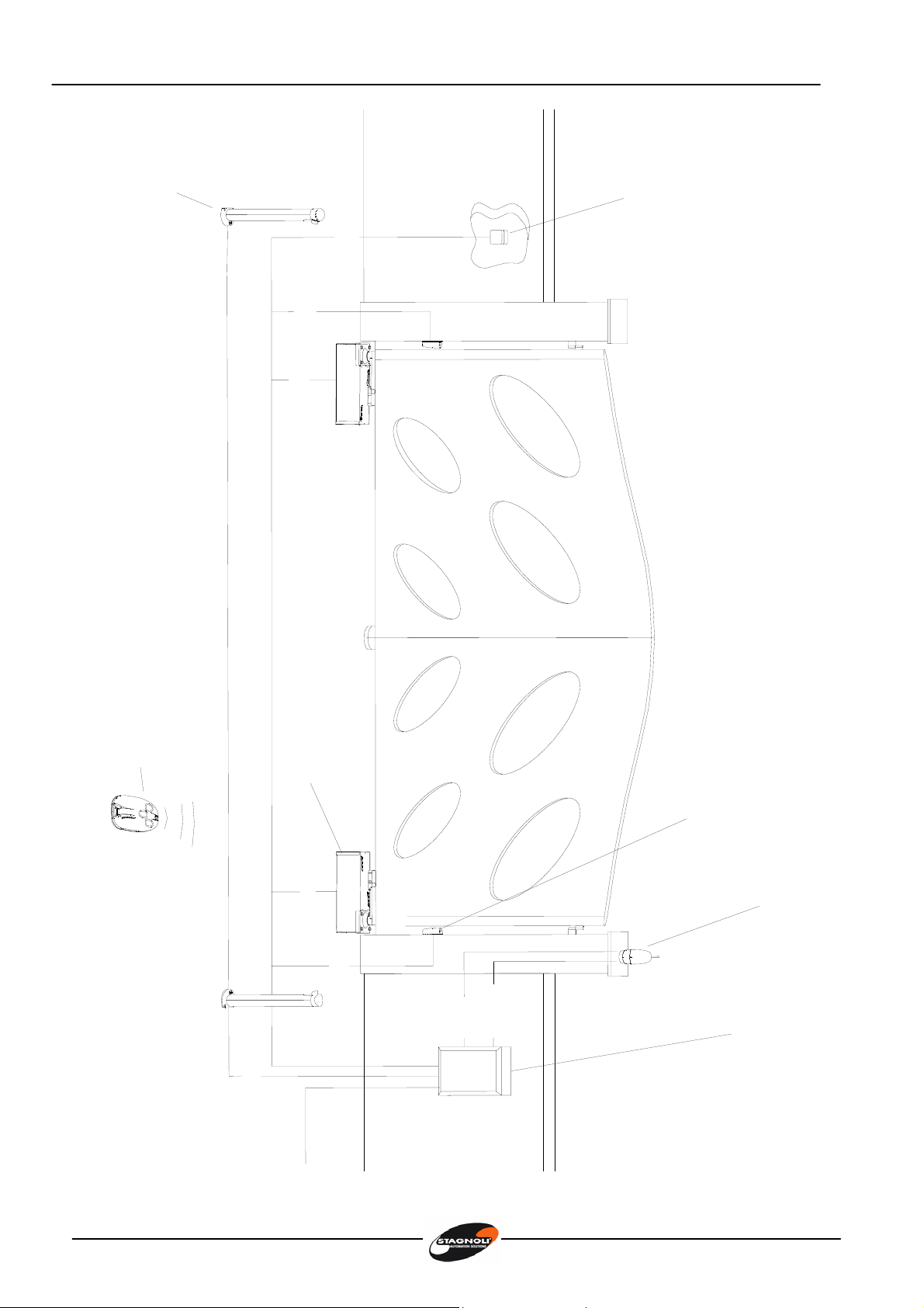
4x1RX
2x1
2x1TX4x1.54x1.5
4x1RX
TRG58
2x1.5
2x1-TX
3x1.5
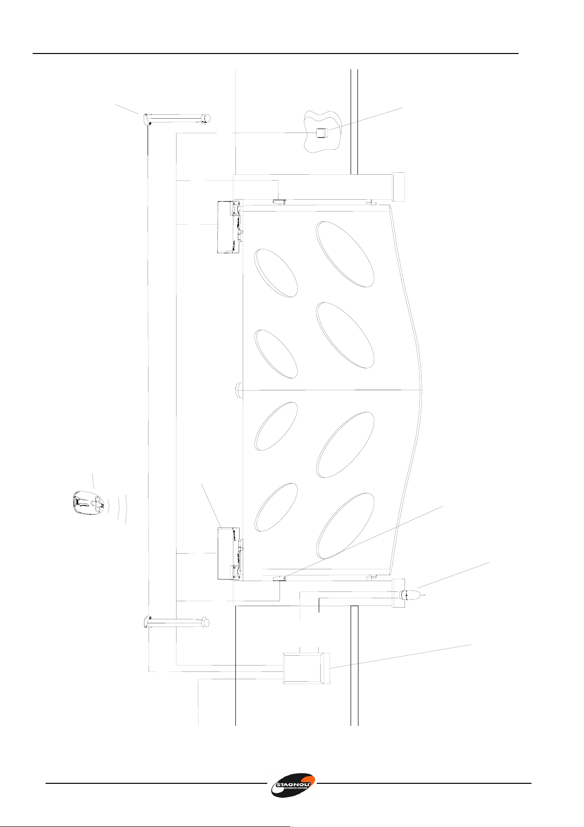
230V
ZEFIRO-180 230V
Applicazione residenziale
Lampeggiante
PEGASUS
Quadro
comando
Fotocellulaa
muroARGO
Motoreinterrato
ZEFIRO-180
Selettorea
chiaveASM
Fotocellulaacolonna
POLIFEMOTrasmettitore
ZEUS
Istruzioni instructions Instructions Instrucciones Anleitungen
5
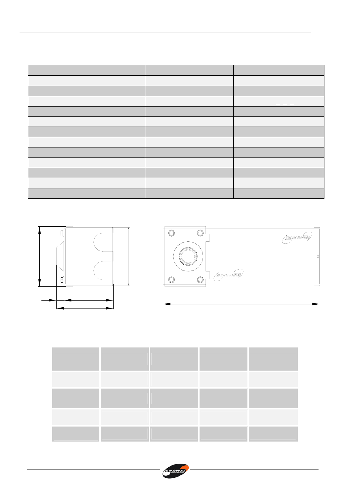
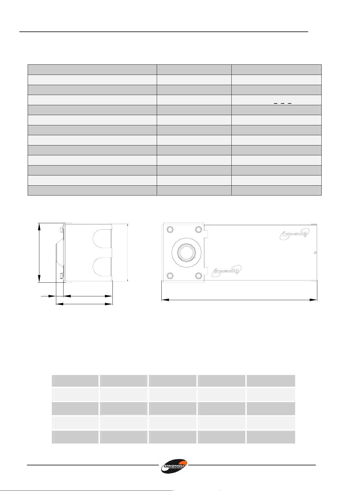
Caratteristiche tecniche Zefiro - 180
Dati tecnici ZEFIRO-180 230V ZEFIRO-180 24V
Alimentazione 230V~ 50Hz 230V~ 50Hz
Corrente assorbita (A) 1,3 1
Alimentazione motore 230V~ 24V–––––
Potenza assorbita mot. (W) 160 120
Condensatore 10µF -
Tempo di manovra 90° (sec) 16-20 16-20
Coppia (Nm) 180 180
Temperatura operativa (°C) -20….+60 -20…..+60
Termoprotezione (°C) 150 -
Duty cycle (%) 30 70
Livello di protezione IP 67 67
Peso (Kg) 9 9
156
420
153
133
161
20
Limiti di impiego
ANTA 1 m 1,5 m 1,8 m 2 m
300 kg
250 kg
200 kg
150 kg
Istruzioni instructions Instructions Instrucciones Anleitungen
6
Verifiche preliminari
•Controllare che la struttura del cancello sia sufficientemente robusta e che non ci
siano punti di attrito.
•Controllare che le cerniere del cancello siano efficienti e siano adeguatamente
lubrificate.
•Verificare che ci siano i fermi meccanici d’arresto in chiusura ed in apertura.
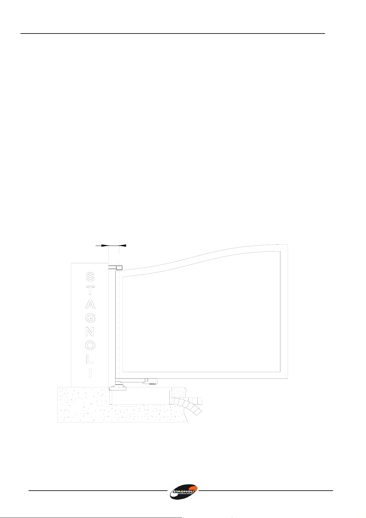
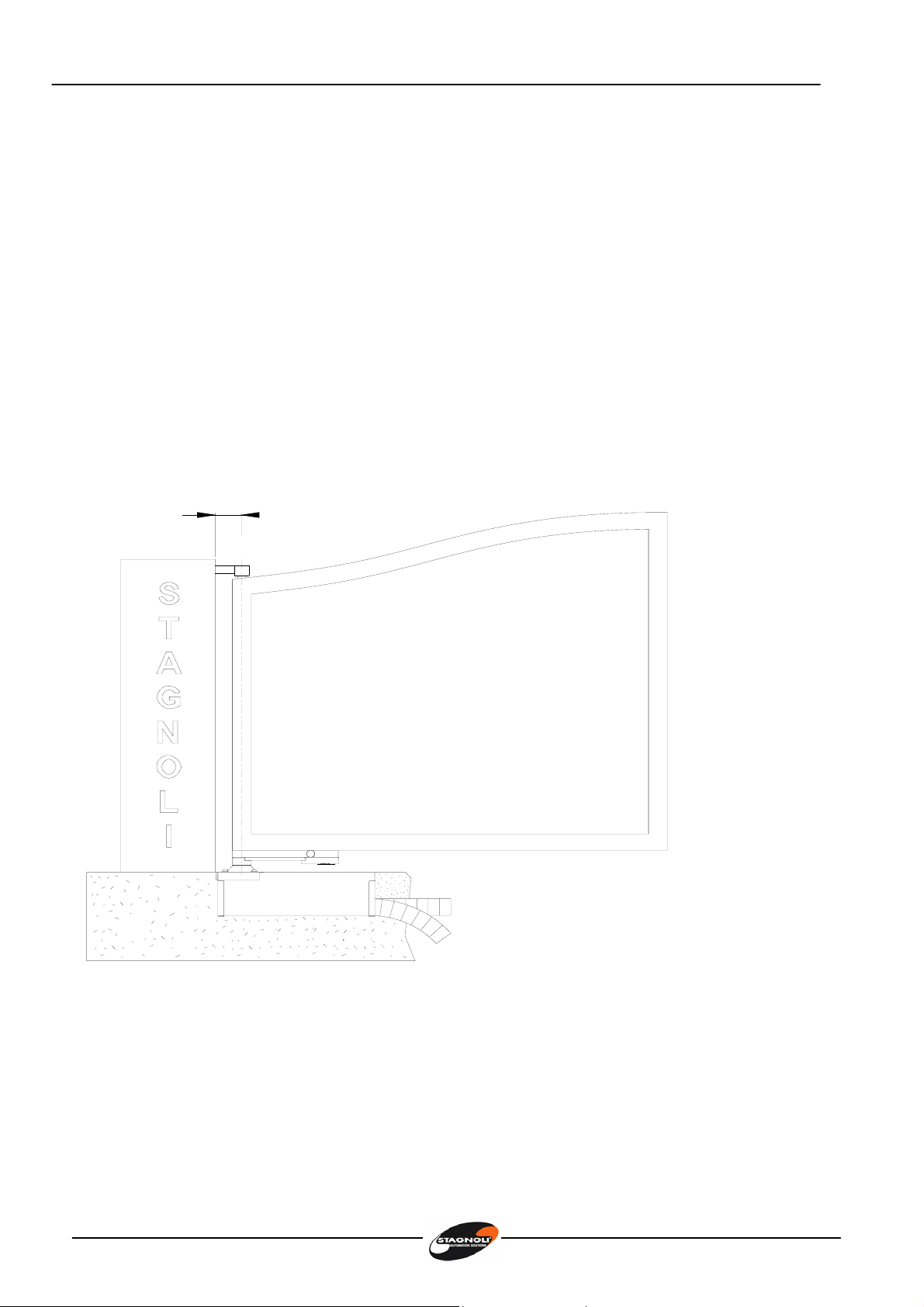
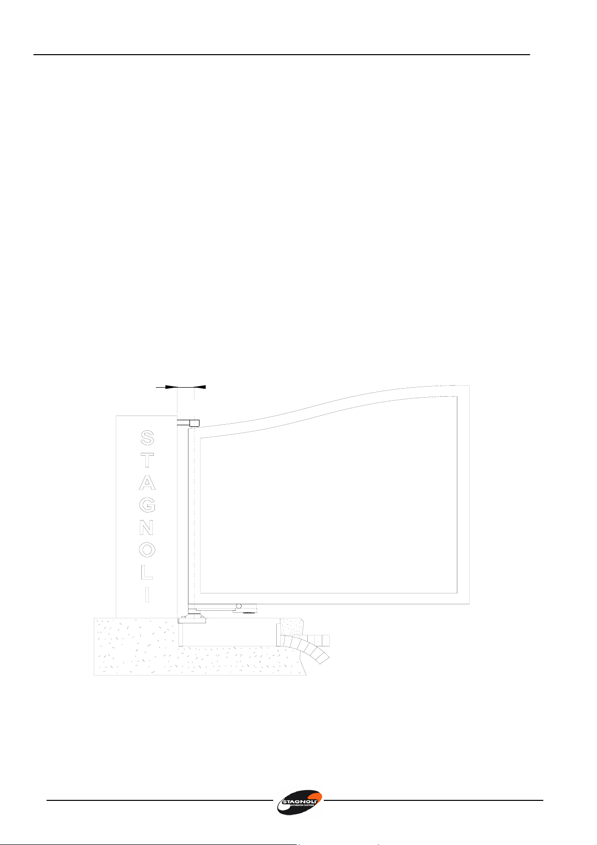
Installazione cassa di fondazione (Fig. 1)
•Predisporre uno scavo adeguato secondo le misure d’ingombro della cassa di
fondazione ( a ).
•Predisporre un tubo per il passaggio cavi in corrispondenza del relativo foro sulla cassa
di fondazione ( b ).
•Predisporre un tubo per il drenaggio acqua ( b ).
•Posizionare la cassa di fondazione all’interno dello scavo avendo cura di rispettare la
quota come da ( c ).
70
a)
c)
b)
fig. 1
Istruzioni instructions Instructions Instrucciones Anleitungen
7
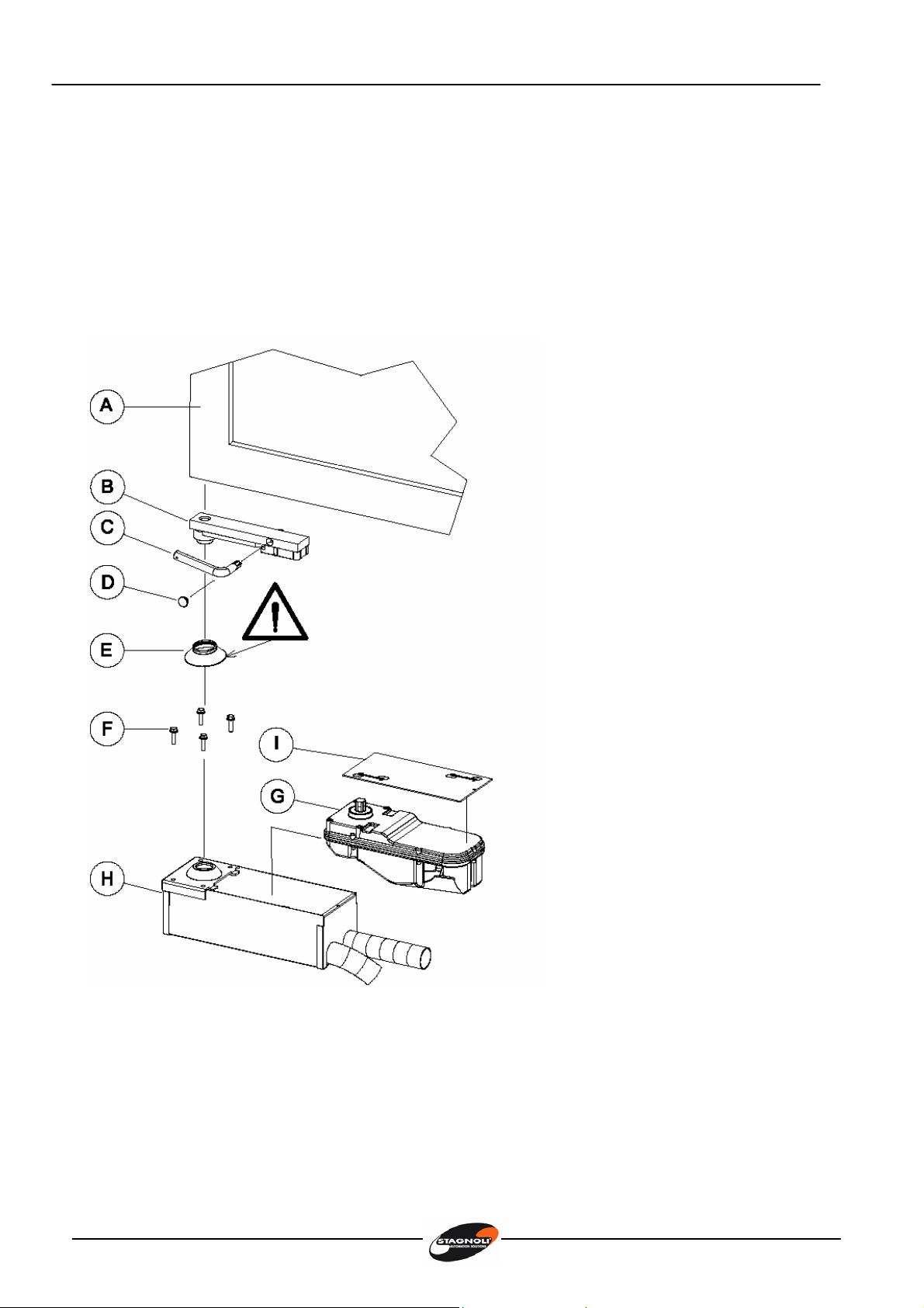
Installazione motoriduttore (Figura 2)
L’installazione del motoriduttore (G) prevede il suo alloggiamento all’interno della cassa di
fondazione (H), la sua chiusura, e il fissaggio, tramite una saldatura accurata, del supporto
(B) all’anta del cancello (A).
A. Anta cancello
B. Supporto con sblocco
manuale
C. Leva sblocco manuale
D. Tappo supporto
E. Guarnizione di gomma
F. Viti fissaggio
motoriduttore alla cassa
di fondazione
G. Motoriduttore
H. Cassa di fondazione
I. Coperchio cassa di
fondazione
fig. 2
Istruzioni instructions Instructions Instrucciones Anleitungen
8
Collegamenti elettrici Zefiro-180 versione 230V
Collegare il motoriduttore alla centrale seguendo le indicazioni in figura e le istruzioni della
centrale di comando.
NERO = FASE APERTURA
MARRONE = FASE CHIUSURA
BLU = COMUNE
GIALLO/VERDE
=
MESSA A TERRA
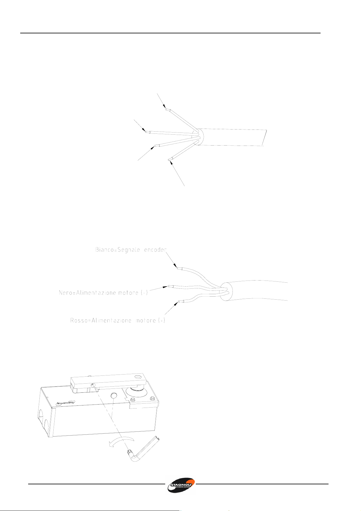
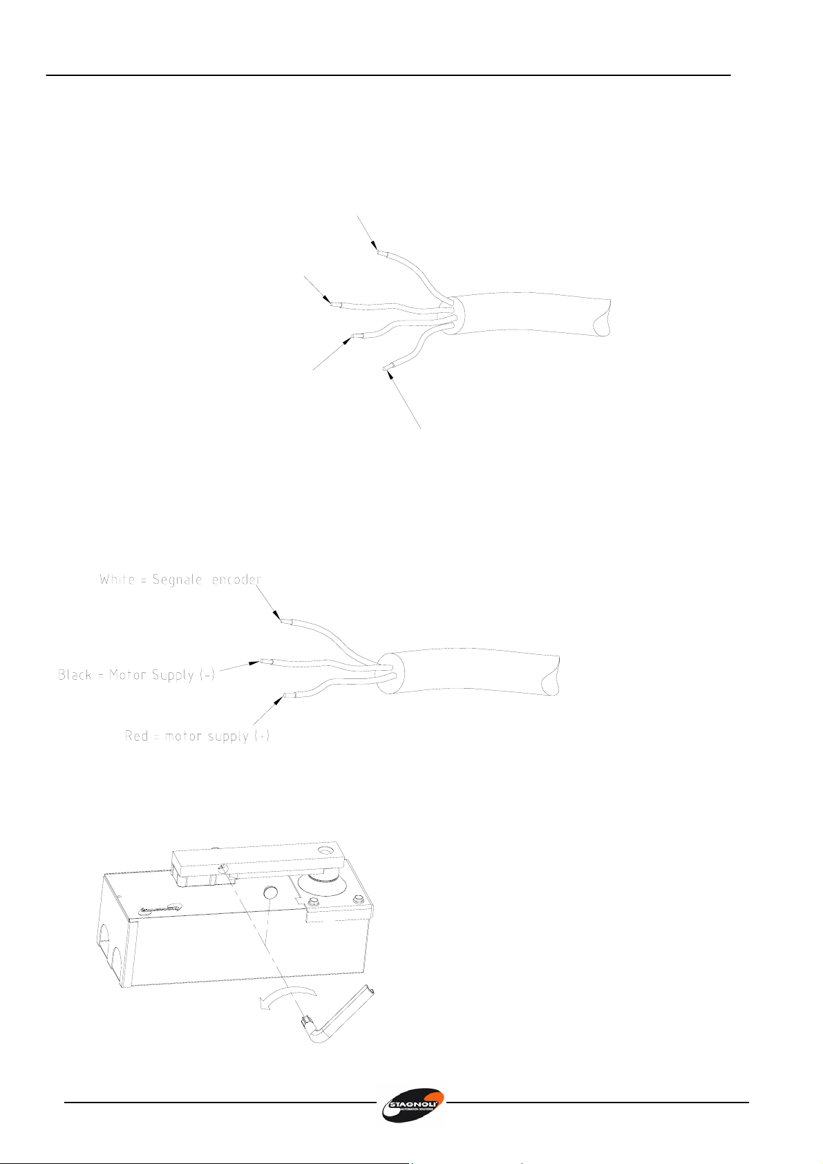
Collegamenti elettrici Zefiro-180 versione 24V
Collegare il motoriduttore alla centrale seguendo le indicazioni in figura e le istruzioni della
centrale di comando.
Sblocco manuale
•Togliere il tappo
•Inserire la chiave e ruotarla di 90°
•Agire manualmente sull’anta
Istruzioni instructions Instructions Instrucciones Anleitungen
9
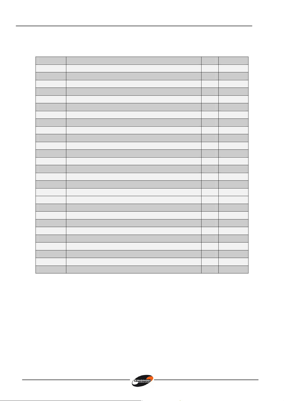
Catalogo componenti Zefiro 180 (pag. 38-39)
Posizione Componente Q.tà Codice
1 Carter superiore 230V 1 X61A700
2 Carter inferiore 230V 1 X61A701
3 Guarnizione anello OR 41200 1 X61A702
4 Viti fissaggio carter 7 X61A450
5 Albero con rotore 1 X61A605
6 Statore avvolto 6 poli 1 X61A470
7 Cuscinetto motore elettrico tipo 6202 zz 1 X61A703
8 Cuscinetto motore elettrico tipo 6201 zz 1 X61A249
9 Morsettiera 4 poli con lamella 1 X61A428
10 Pressacavo metallico M16x1,5 1 X61A705
11 Vite senza fine seconda riduzione Ø50 1 X61A706
12 Ingranaggio in bronzo Z45 1 X61A707
13 Linguetta UNI 6604 8x7x18 1 X61A507
14 Cuscinetto tipo 6205 zz 2 X61A708
15 Albero con ingranaggio seconda riduzione Z33 1 X61A717
17 Cuscinetto tipo 6005 zz 2 X61A525
18 Anello di tenuta DIN 3760 25x47x7 1 X61A711
20 Cavo elettrico 4x1,5mm² 1 X61A839
29 Carter superiore 24V 1 X61A718
30 Carter inferiore 24V 1 X61A719
33 Motore elettrico 24V 1
38 Disco encoder ottico 1 SENC
39 Vite fissaggio encoder M4x25 1 X61A608
40 Scheda elettronica per encoder 1 X61A847
41 Viti fissaggio scheda elettronica encoder 1 X61A494
42 Coperchio di protezione encoder 1 SC
43 Cavo elettrico 2x2,5 mm² + 1x0,5 mm² 1 AKTFROR
Istruzioni instructions Instructions Instrucciones Anleitungen
10
Attention!
•This manual is for qualified installers only and not for the end user. It is the
installer’s job to explain to the user how the automatism works, about possible
hazards related to it and the need for periodical maintenance.
•Installation must be carried out by qualified personnel only, observing current
standards concerning automatic closing systems. More specifically, installation
conformity calls for observance of directive 89/392 and standards EN 12453 and
EN 12445.
•ZEFIRO-180 has been made specifically to control the automation of swing
gates and it is therefore forbidden to use it for any other purpose or improperly.
•Use original components only. Stagnoli is not liable for damages if any other
components are used.
•Make absolutely certain the power is disconnected before carrying out any
work on the device.
•Be particularly careful when evaluating the safety devices to install and their
location. Always install an emergency stop device that will cut power off in the
case of necessity.
•The power lead must only be connected to supply lines fitted with adequate
electrical protection; a circuit breaker must also be installed to guarantee
disconnection of all the phases from the mains with a distance of at least 3.5
mm between the contacts.
•Only qualified personnel must be allowed to service the unit, including changing
the courtesy light bulb whenever needed.
•Make sure that the gate structure is solid, well balanced and suitable to be
motorised. Also ensure there are no points of friction when the gate is moving.

Istruzioni instructions Instructions Instrucciones Anleitungen
11
4x1RX
2x1
2x1TX4x1.54x1.5
4x1RX
TRG58
2x1.5
2x1-TX
Controlpanel
3x1.5
230V
Undergroundgear
motorZEFIRO-180
PEGASUS
Blinker
ASM1Key
selector
ARGO
Wallmounted
photocell
ZEFIRO-180 230V
Residential application
POLIFEMOpost
mountedphotocellZEUS
Transmitter

Istruzioni instructions Instructions Instrucciones Anleitungen
12
Zefiro – 180 technical specifications
Technical data ZEFIRO-180 230V ZEFIRO-180 24V
Supply 230V~ 50Hz 230V~ 50Hz
Input current (A) 1.3 1
Motor supply 230V~ 24V–––––
Motor power (W) 160 120
Capacitor 10µF -
Manoeuvre time 90° (sec) 16-20 16-20
Torque (Nm) 180 180
Working temperature (°C) -20….+60 -20…..+60
Thermal overload
protection (°C)
150 -
Duty cycle (%) 30 70
IP protection level 67 67
Weight (Kg) 9 9
156
420
153
133
161
20
Limits of use
GATE 1 m 1.5 m 1.8 m 2 m
300 kg
250 kg
200 kg
150 kg
Istruzioni instructions Instructions Instrucciones Anleitungen
13
Preliminary checks
•Check that the gate structure is sufficiently sturdy and there are no points of friction.
•Make sure the gate hinges are working properly and adequately lubricated.
•Check there are mechanical stops in closing and opening
Installing the foundation box (Fig. 1)
•Prepare a suitable hole to house the foundation box (a).
•Lay a pipe for the cables by the hole in the foundation box (b).
•Prepare a pipe for draining water (b).
•Sit the foundation box inside the hole, keeping to the measurements given in (c).
70
a)
c)
b)
fig. 1

Istruzioni instructions Instructions Instrucciones Anleitungen
14
Installing the gear motor (Figure 2)
Install the gear motor (G) by placing it inside the foundation box (H), closing the box and
then accurately welding the support (B)to the gate wing (A).
A. Gate wing
B. Support with manual
release
C. Manual release lever
D. Support cap
E. Rubber gasket
F. Screws for fixing the
gear motor to the
foundation box
G. Gear motor
H. Foundation box
I. Foundation box lid
fig. 2
Istruzioni instructions Instructions Instrucciones Anleitungen
15
Electrical connections of the 230V version of Zefiro-180
Connect the gear motor to the control unit following the indications given in the figure
and the control unit instructions.
BLACK = OPENING PHASE
BROWN = CLOSING PHASE
BLUE = COMMON
YELLOW/GREEN = GROUND
Electrical connections of the 24V version of Zefiro-180
Connect the gear motor to the control unit following the indications given in the figure
and the control unit instructions.
Manual release
•Remove the cap
•Put the key in and turn it 90°
•Move the gate by hand

Istruzioni instructions Instructions Instrucciones Anleitungen
16
Spare parts catalogue (Pag. 38-39)
Item Component Qty Code
1 Upper casing 230V 1 X61A700
2 Lower casing 230V 1 X61A701
3 O ring 41200 1 X61A702
4 Casing securing screws 7 X61A450
5 Shaft with rotor 1 X61A605
6 6-pole wound stator 1 X61A470
7 6202 zz type electric motor bearing 1 X61A703
8 6201 zz type electric motor bearing 1 X61A249
9 4-pole terminal block with segment 1 X61A428
10 M16x1.5 metal cable clamp 1 X61A705
11 Worm screw second reduction Ø50 1 X61A706
12 Bronze gear Z45 1 X61A707
13 Feather key UNI 6604 8x7x18 1 X61A507
14 6205 zz type bearing 2 X61A708
15 Shaft with gear second reduction Z33 1 X61A717
17 6005 zz type bearing 2 X61A525
18 Sealing ring DIN 3760 25x47x7 1 X61A711
29 Upper casing 24V 1 X61A718
30 Lower casing 24V 1 X61A719
33 Electric motor 24V 1
38 Optical encoder disk 1 SENC
39 Encoder securing screw M4x25 1 X61A608
40 Electronic card for encoder 1
41 Securing screws for electronic encoder card 1
42 Encoder protection cover 1
43 Electric cable 2x2.5 mm² + 1x0.5 mm² 1
61 Electric cable 4x1.5mm² 1

Istruzioni instructions Instructions Instrucciones Anleitungen
17
attention !
•Le présent manuel n’est destiné qu’au personnel technique qualifié pour
effectuer l’installation et non pas à l’utilisateur final; c’est à l’installateur
d’informer ensuite l’utilisateur sur le mode d’emploi de l’automatisme, sur les
dangers pouvant dériver de son utilisation et sur la nécessité d’un entretien
périodique.
•L’installation doit être effectuée uniquement par du personnel qualifié qui doit
respecter les normes en vigueur concernant les fermetures automatisées. En
particulier la conformité de l’installation prévoit le respect de la directive 89/392
et des normes EN 12453 et EN 12445.
•ZEFIRO-180 a été conçu pour la gestion de portails a battants, ne pas utiliser le
produit dans un but différent de celui prévu ou de manière inappropriée.
•Utiliser des composants originaux. L’entreprise Stagnoli ne s’assume aucune
responsabilité pour des dommages dus à l’utilisation de composants non originaux.
•Avant d’intervenir sur le dispositif s’assurer que l’alimentation est bien
débranchée.
•Evaluer avec une attention particulière les dispositifs de sécurité à installer et
l’endroit de leur mise en place, en outre il faut prévoir un dispositif d’arrêt
d’urgence permettant la coupure obligatoire de l’alimentation.
•Ne brancher le câble de la tension qu’à des lignes d’alimentation équipées de
protections électriques appropriées; il faut prévoir en particulier un dispositif
pour assurer la déconnexion omnipolaire du réseau, avec une distance d’au
moins 3.5 mm entre les contacts.
•Les opérations de maintenance, y compris le remplacement de la lampe de
courtoisie, ne doivent être effectuées seulement et uniquement que par du
personnel qualifié.
•Vérifier si la structure du portail est bien solide, équilibrée et si elle peut être
motorisée sans problèmes, vérifier également s'il ne présente aucun point de
friction pendant le mouvement.
Istruzioni instructions Instructions Instrucciones Anleitungen
18
4x1RX
2x1
2x1TX4x1.54x1.5
4x1RX
TRG58
2x1.5
2x1-TX
3x1.5
230V
ZEFIRO-180 230V
Application résidentiel
SélecteuràcléASM 1
Cellule
photoélectrique
muraleARGO
Cellule photoélectrique à colonne
POLIFEMO
Clignotant
PEGASUS
Moteurenterré
Zefiro-180
Tableaude
commande
Transmetteur
ZEUS
Istruzioni instructions Instructions Instrucciones Anleitungen
19
Caractéristiques techniques Zefiro - 180
Données techniques ZEFIRO-180 230V ZEFIRO-180 24V
Alimentation 230V~ 50Hz 230V~ 50Hz
Courant absorbé (A) 1,3 1
Alimentation moteur. 230V~ 24V–––––
Puissance absorbée mot. (W) 160 120
Condensateur 10µF -
Temps de manoeuvre 90° (sec) 16-20 16-20
Couple (Nm) 180 180
Température opérationnelle (°C) -20….+60 -20…..+60
Protection thermique (°C) 150 -
Duty cycle (%) 30 70
Niveau de protection IP 67 67
Poids (Kg) 9 9
156
420
153
133
161
20
Limites d’emploi
VANTAIL 1 m 1,5 m 1,8 m 2 m
300 Kg
250 Kg
200 Kg
150 Kg
Istruzioni instructions Instructions Instrucciones Anleitungen
20
Contrôles préliminaires
•Contrôler si la structure du portail est suffisamment robuste et s’il n’y a aucun point de
friction.
•Contrôler si les charnières du portail fonctionnent correctement et si elles sont bien
graissées.
•Vérifier la présence de crans mécaniques d’arrêt en fermeture et en ouverture.
Installation du caisson de fondation (Fig. 1)
•Creuser un trou correspondant aux dimensions du caisson de fondation (a).
•Installer un tube pour faire passer des câbles en correspondance du trou prévu à cet
effet sur le caisson de fondation (b).
•Installer un tube pour le drainage de l’eau (b).
•Mettre le caisson de fondation dans le trou en suivant les indications pour respecter la
cote ( c ).
70
a)
c)
b)
fig. 1
Table of contents
Languages:
Other Stagnoli Engine manuals


