ECOSTAR liftronic 500 Manual

TR10L003-B RE / 12.2013
DE Anleitung für Montage, Betrieb und Wartung
Garagentor-Antrieb
EN Instructions for Fitting, Operating and Maintenance
Garage door operator
FR Instructions de montage, d‘utilisation et d‘entretien
Motorisation de porte de garage
NL Handleiding voor montage, werking en onderhoud
Garagedeuraandrijving
IT Istruzioni per il montaggio, l‘uso e la manutenzione
Motorizzazione per portoni da garage
ES Instrucciones de montaje, funcionamiento y mantenimiento
Automatismo para puertas de garaje
PT Instruções de montagem, funcionamento e manutenção
Automatismo para portas de garagem
www.thegaragedoorcentre.co.uk
0800 525 442
www.thegaragedoorcentre.co.uk

C1Extended fitting bracket
If the clearance between the highest point of the door and the ceiling is less than
30mm, the garage door operator can also be mounted behind the opened door if
enough space is available. In the following cases, an extended fitting bracket must
be used:
– For a lintel with offset of 1,000mm
– For sectional doors (track application N) up to 2,375 mm high
– For sectional doors (track application L or Z) up to 2,250 mm high
– For up-and-over doors up to 2,750 mm high
C2Fitting bracket for sectional doors
For doors of other makes
C3Hand transmitter RSC2 (including hand transmitter holder)
This hand transmitter works with a rolling code (frequency: 433MHz) that changes
with each sending procedure. The hand transmitter is equipped with two buttons,
i.e.you can use the second button to open another door or turn on the outdoor lights
if there is an optional receiver for it.
C4Hand transmitter RSZ1
This hand transmitter fits in a vehicle cigarette lighter. The hand transmitter works
with a rolling code (frequency: 433MHz) that changes with each sending procedure.
C5Internal push button PB3
The internal push button can be used to conveniently open and close your door from
within the garage, turn on the light and block radio control.
Including a 7m connecting lead (2-wire) and fixing material
C6Radio code switch RCT3b
Up to 3 door operators can be wirelessly operated via impulse using the illuminated
radio code switch. This does away with the time-consuming need to lay cables.
C7Surface-mounted / recessed key switch
You can use the key switch to operate the garage door operator from the outside
with a key. Two versions in one device – surface-mounted or recessed.
C8
S
ilca
LS 11
Silca
LS 11
Emergency release lock NET3
Necessary for garages without a second entrance.
– Bore Ø 13mm
– Cable length 1.5m
C9Receiver RERI1 / RERE1
This 1-channel receiver enables operation of a garage door operator with one
hundred additional hand transmitters (buttons).
Memory spaces: 100
Frequency: 433MHz (rolling code)
Operating voltage: 24V AC / DC or 230 / 240V AC
Relay output: On/off
C10 One-way photocell EL101
For indoor use as additional safety device
Including 2 × 10m connecting lead (2-wire) and fixing material.
TR10L003-B RE / 12.2013 19
ENGLISH
www.thegaragedoorcentre.co.uk
0800 525 442
www.thegaragedoorcentre.co.uk

1 About These Instructions..................................... 21
1.1 Further applicable documents................................ 21
1.2 Warnings used ........................................................ 21
1.3 Definitions used ...................................................... 21
1.4 Symbols used ......................................................... 21
2 Safety instructions ....................................... 22
2.1 Intended use ........................................................... 22
2.2 Inappropriate use.................................................... 22
2.3 Fitter qualification ................................................... 22
2.4 Safety instructions for fitting, maintenance,
repairs and disassembly of the door system.......... 22
2.5 Safety instructions for fitting................................... 22
2.6 Safety instructions for initial
start-up and operation............................................ 23
2.7 Safety instructions for using
the hand transmitter................................................ 23
2.8 Approved safety equipment.................................... 23
3 Fitting ..................................................................... 23
3.1 Inspecting the door / door system .......................... 23
3.2 Clearance required ................................................. 23
3.3 Preparation on a sectional door.............................. 24
3.4 Preparation on an up-and-over door...................... 24
3.5 Fitting the operator boom....................................... 24
3.6 Fitting the garage door operator............................. 24
3.7 Determining the door end-of-travel positions......... 25
3.8 Emergency release.................................................. 25
3.9 Fixing the warning sign........................................... 25
4 Initial Start-Up / Connecting
Additional Components........................................ 25
4.1 Display and control elements ................................. 26
4.2 Teaching in the operator......................................... 26
4.3 Connecting additional
components / accessories ...................................... 26
4.4 DIL switch functions ............................................... 26
5 Radio...................................................................... 27
5.1 Hand transmitter RSC 2.......................................... 27
5.2 Excerpt from the declaration of conformity............ 27
5.3 Integral radio receiver ............................................. 27
5.4 Teaching in hand transmitters................................. 27
5.5 Operation ................................................................ 28
5.6 Deleting all memory spaces.................................... 28
Table of Contents
Dissemination as well as duplication of this document and the
use and communication of its content are prohibited unless
explicitly permitted. Noncompliance will result in damage
compensation obligations. All rights reserved in the event of
patent, utility model or design model registration. Subject to
changes.
6 Operation............................................................... 28
6.1 Instructing users ..................................................... 28
6.2 Function tests ......................................................... 28
6.3 Normal operation .................................................... 29
6.4 Behaviour during a power failure............................ 29
6.5 Behaviour following a power failure........................ 29
7 Inspection and Maintenance ............................... 29
7.1 Checking the tension of the toothed belt ............... 29
7.2 Checking safety reversal / reversing........................ 29
7.3 Exchanging the bulb............................................... 30
8 Displays for Operating
Conditions, Errors and Warnings ........................ 30
8.1 Operator light messages........................................ 30
8.2 Display of error and warning messages ................. 30
9 Deleting Door Data ............................................... 31
10 Dismantling and Disposal .................................... 31
11 Warranty Conditions............................................. 31
12 Excerpt from the Declaration of Incorporation.. 32
13 Technical Data....................................................... 32
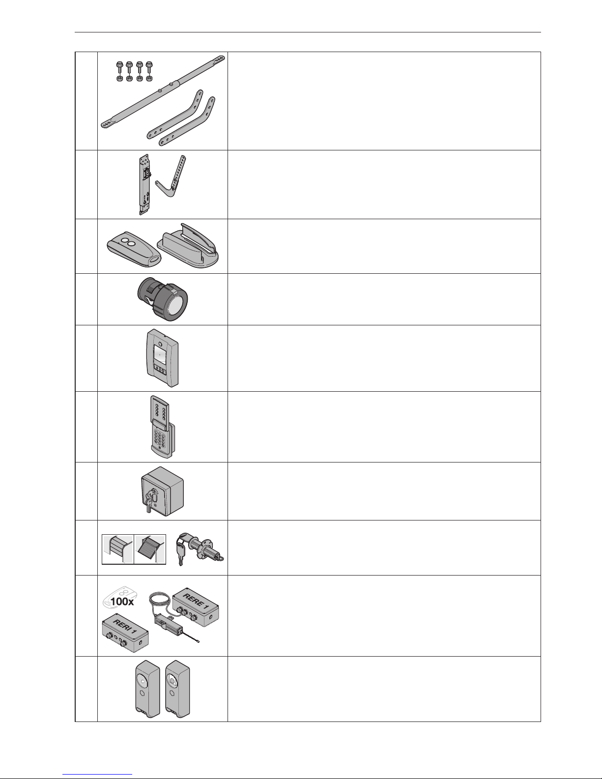
A Articles supplied ..................................................... 2
B Tools needed for fitting the garage door
operator ................................................................... 2
C Accessories for the garage door operator......... 19
D Spare parts .......................................................... 131
Drill stencil........................................................... 129
Illustrated section..................................... 108
20 TR10L003-B RE / 12.2013
ENGLISH
www.thegaragedoorcentre.co.uk
0800 525 442
www.thegaragedoorcentre.co.uk

Dear Customer,
We are delighted that you have decided to choose a quality
product from our company.
1 About These Instructions
These instructions are original operating instructions as
outlined in the EC Directive2006/42/EC. Read through all of
the instructions carefully, as they contain important
information about the product. Pay attention to and follow the
instructions provided, particularly the safety instructions and
warnings.
Keep these instructions in a safe place for later reference!
1.1 Further applicable documents
The following documents for safe handling and maintenance
must be provided:
• These instructions
• The enclosed test log book
• The garage door operating instructions
1.2 Warnings used
The general warning symbol indicates a danger that
can lead to injury or death. In the text section, the general
warning symbol will be used in connection with the caution
levels described below. In the illustrated section, an
additional instruction refers back to the explanation in the
text.
DANGER
Indicates a danger that leads directly to death or serious
injuries.
WARNING
Indicates a danger that can lead to death or serious injuries.
CAUTION
Indicates a danger that can lead to minor or moderate
injuries.
ATTENTION
Indicates a danger that can lead to damage or destruction
of the product.
1.3 Definitions used
DIL switches
Switches located under the side flap of the operator cover for
activating the operator functions.
Impulse sequence control
With each push of the button, the door is started against the
previous direction of travel, or the motion of the door is
stopped.
Learning runs
Door runs in which the forces necessary for door travel are
taught in.
Normal operation
Door travel with the taught-in travel distances and forces.
Reference run
Door travel towards the OPEN end-of-travel position in order
to set the home position.
Reversing cycle / safety reversal
Door travel in the opposite direction when the safety device or
force limit is activated.
Travel
The distance the door takes to traverse from the OPEN end-
of-travel position to the CLOSE end-of-travel position.
1.4 Symbols used
The illustrated section shows how to fit an operator on a
sectional door. Deviating fitting steps for an up-and-over door
are also shown. To identify the various types, the following
letters are assigned to the figures:
(a) = Sectional door (b) = Up-and-over door
All dimensions in the illustrated section are in [mm].
Symbols:
See text section
In the example, 2.2 means: See text
section2.2
Important advice to prevent injury to
persons and damage to property
High force required
Little force required
Check for smooth running
TR10L003-B RE / 12.2013 21
ENGLISH
www.thegaragedoorcentre.co.uk
0800 525 442
www.thegaragedoorcentre.co.uk

Use protective gloves
Audible engagement
Inspect
DIL switch factory setting
2 Safety instructions
2.1 Intended use
The garage door operator is intended exclusively for the
impulse operation of spring-compensated sectional doors
and up-and-over doors in the private / non-commercial sector.
Note the manufacturer's specifications regarding the door and
operator combination. Potential hazards as outlined in
DINEN13241-1 are avoided by construction and fitting
according to our guidelines. Door systems that are located in
a public area and only have one protective device, such as a
force limit, may only be operated under supervision.
The garage door operator is designed for operation in dry
areas.
2.2 Inappropriate use
Continuous operation and use in the commercial sector is
prohibited.
The operator must not be used for doors without a safety
catch.
The operator may not be used in conjunction with timber
doors.
2.3 Fitter qualification
Only correct fitting and maintenance in compliance with the
instructions by a competent / specialist company or a
competent / qualified person ensures safe and flawless
operation of the system. According to EN12635, a qualified
person is a person with suitable training, specialist knowledge
and practical experience sufficient to correctly and safely fit,
test, and maintain a door system.
2.4 Safety instructions for fitting, maintenance,
repairs and disassembly of the door system
DANGER
Compensating springs are under high tension
▶ See warning in section3.1
WARNING
Danger of injury due to unexpected door travel
▶ See warning in section7
Fitting, maintenance, repairs, and disassembly of the door
system and garage door operator must be performed by a
specialist.
▶ In the event of a failure of the garage door operator, a
specialist must be commissioned immediately for the
inspection or repair work.
2.5 Safety instructions for fitting
The specialist carrying out the work must ensure that
installation is conducted in compliance with the prevailing
national job safety rules and regulations and those governing
the operation of electrical equipment. The relevant national
directives must be observed. Potential hazards as outlined in
DINEN13241-1 are avoided by construction and fitting
according to our guidelines.
The garage ceiling must guarantee secure fastening of the
operator. For ceilings which are too high or too light, the
operator must be fastened on additional struts.
DANGER
Mains Voltage
▶ See warning in section4
WARNING
Unsuitable fixing material
▶ See warning in section3.6
Danger to life from the rope
▶ See warning in section3.6
Danger of injury due to unwanted door travel
▶ See warning in section3.6
CAUTION
Crushing hazard during boom fitting!
▶ See warning in section3.5
22 TR10L003-B RE / 12.2013
ENGLISH
www.thegaragedoorcentre.co.uk
0800 525 442
www.thegaragedoorcentre.co.uk

2.6 Safety instructions for initial start-up and
operation
WARNING
Danger of injury during door travel
▶ See warning in section6
Danger of injury by fast-closing door
▶ See warning in section6.2.1
CAUTION
Crushing hazard in the boom
▶ See warning in section6
Danger of injury from the cord knob
▶ See warning in section6
Danger of injuries due to the hot lamp
▶ See warning in section6 and 7.3
2.7 Safety instructions for using the hand
transmitter
WARNING
Danger of injury during unwanted door travel
▶ See warning in section5
CAUTION
Danger of injuries due to unintended door travel
▶ See warning in section5
2.8 Approved safety equipment
Safety relevant functions or components of the control, such
as the force limit, external photocells and closing edge safety
device, have been designed and approved in accordance with
category2, PL“c” of ENISO13849-1:2008.
WARNING
Danger of injuries due to faulty safety equipment
▶ See warning in section 4.2
3 Fitting
3.1 Inspecting the door / door system
DANGER
Compensating springs are under high tension
Serious injuries may occur while adjusting or loosening the
compensating springs!
▶ For your own safety, only have a specialist conduct
work on the door compensating springs and, if
necessary, maintenance and repair work!
▶ Never try to replace, adjust, repair or reposition the
compensating springs for the counterbalance of the
door or the spring mountings yourself.
▶ Furthermore, inspect the entire door system (joints,
door bearings, cables, springs and fastening parts) for
wear and possible damage.
▶ Check for the presence of rust, corrosion, and cracks.
A fault in the door system or an incorrectly aligned door
may lead to serious injuries!
▶ Do not use the door system if repair or adjustment
work must be conducted!
The construction of the operator is not designed for operation
with sluggish doors, that is, doors that can no longer be
opened or closed manually, or can only be opened / closed
manually with difficulty.
The door must be in perfect mechanical condition, so that it is
easy to operate by hand (EN12604).
▶ Lift the door by approx. one metre and let it go.
The door should stay in this position and neither move
downward nor upward. If the door does move in either
direction, there is a danger that the compensating
springs / weights are not properly adjusted or are
defective. In this case, increased wear and
malfunctioning of the door system can be expected.
▶ Check whether the door can be opened and closed
correctly.
▶ The mechanical locking devices of the door that are not
needed with a garage door operator must be put out of
commission. This especially includes the locking
mechanisms of the door lock (see section3.3.1 and
section3.4.1).
▶ Switch to the illustrated section for the fitting and
initial start-up. Observe the respective text section
when you are prompted to by the symbol for the text
reference.
3.2 Clearance required
▶ See figure1.1a / 1.2b
The clearance between the highest point of the door travel
and the ceiling must be at least 30mm.
If the clearance is smaller, the operator can also be mounted
behind the opened door if enough space is available. In such
cases, an extended fitting bracket has to be used, which must
be ordered separately (see Accessories for the garage door
operator / C1).
The garage door operator can be arranged up to max. 50 cm
off-centre. The electric socket necessary for the electrical
connection should be fitted approx.50cm from the operator
head (note section4 Mains voltage).
▶ Check these dimensions!
TR10L003-B RE / 12.2013 23
ENGLISH
www.thegaragedoorcentre.co.uk
0800 525 442
www.thegaragedoorcentre.co.uk

3.3 Preparation on a sectional door
3.3.1 Door locking on the sectional door
▶ See figure1.3a
▶ Completely disassemble the mechanical door locking on
the sectional door.
3.3.2 Off-centre reinforcement profile on a sectional
door
▶ See figure1.5a
▶ With an off-centre reinforcement profile on the sectional
door, fit the link bracket on the nearest reinforcement
profile to the left or right.
3.3.3 Centre locking on a sectional door
▶ See figure1.6a
▶ For sectional doors with centre door locking, arrange the
lintel joint and link bracket max.50cm off-centre. Before
drilling, mark the position of the lintel ceiling console on
the lintel or ceiling. For this purpose, use the supplied
drill stencil in the appendix of these instructions.
3.4 Preparation on an up-and-over door
3.4.1 Door locking on an up-and-over door
▶ See figure1.3b / 1.4b
▶ Render the mechanical door locking on the up-and-over
door inoperable.
▶ For door models not covered here, block the catches
on site.
3.4.2 Up-and-over doors with an ornamental iron
handle
▶ See figure1.5b
▶ In a deviation from the illustrated section, attach the lintel
ceiling console and link bracket max. 50 cm off-centre for
up-and-over doors with ornamental iron door handles.
3.5 Fitting the operator boom
CAUTION
Crushing hazard during boom fitting!
There is a danger of crushing your fingers while fitting the
operator boom.
▶ Make sure that your fingers do not get between the
profile ends.
1. Place the operator head on a clean, level surface with the
base plate facing up.
2. Grease the moveable plastic parts
(see figure2.1 / 2.2 / 3.1 / 6.2).
3. Insert the first boom segment (see figure2.2).
Please note the following:
– The toothed belt must be located in the centre of the
operator disc and be approx.1300mm long on the
left-hand side.
– The toothed belt must not become pinched between
the operator head and boom segment.
– The toothed belt must not be twisted.
4. Turn the operator head around (see figure3).
5. Assemble the cord knob completely and attach it to the
slide carriage (see figure3.1 / 3.2).
6. Fit the lintel ceiling console (see figure4.1 – 4.3).
7. Completely lay out the toothed belt and fit it along with
the lintel ceiling console and slide carriage
(seefigure5.1). While doing so, make sure that the
toothed belt does not become twisted.
8. Close the toothed belt and press in the belt teeth all the
way (see figure5.2).
9. Place the jackets on the centre boom segment
(see figure6.1).
10. Grease the carriage coupling from below (see figure6.1).
11. First, insert the last boom segment in the lintel ceiling
console (see figure6.2).
12. Completely assemble the boom (see figure7.2 / 7.3).
13. Check the toothed belt tension and adjust if necessary
(see section 7.1)
3.5.1 Checking that the slide carriage is easy to move
▶ See figure8.1
1. Make sure that the individual boom segments are aligned
with one another so that there are smooth transitions at
each profile end!
2. Check to make sure that the slide carriage can be easily
moved in the boom. To do this, push the slide carriage
back and forth in the boom once. Repeat this procedure,
if necessary.
3.6 Fitting the garage door operator
▶ See figure8.2 – 8.5
WARNING
Unsuitable fixing material
Use of unsuitable fixing material may mean that the
operator is not securely attached and could come loose.
▶ The fitter must check that the fitting materials supplied
are suitable for the purpose and the intended fitting
location.
▶ Only use the provided fixing materials (plugs) in
concrete ≥B15 (see figures8.3a / 8.4).
WARNING
Danger to life from the rope
A running rope may lead to strangulation.
▶ Remove the rope while fitting the operator
(seefigure1.2a).
WARNING
Danger of injury due to unwanted door travel
Incorrect assembly or handling of the operator may trigger
unwanted door travel that may result in persons or objects
being trapped.
▶ Follow all the instructions provided in this manual.
Incorrectly attached control devices (e.g. buttons) may
trigger unwanted door travel. Persons or objects may be
trapped as a result.
▶ Install control devices at a height
of at least 1.5m (out of the reach
of children).
▶ Fit permanently installed control
devices (such as buttons, etc.)
within sight of the door, but away
from moving parts.
24 TR10L003-B RE / 12.2013
ENGLISH
www.thegaragedoorcentre.co.uk
0800 525 442
www.thegaragedoorcentre.co.uk

ATTENTION
Damage caused by dirt
Drilling dust and chippings can lead to malfunctions.
▶ Cover the operator during drilling work.
The completely assembled operator is fitted on the lintel or
under the ceiling.
1. First, only tighten slightly on the side of the lintel ceiling
console.
2. Determine the drilling positions of the suspensions
fastened to the operator head and fit them securely
under the ceiling.
3. Securely tighten the lintel ceiling console.
3.7 Determining the door end-of-travel positions
▶ See figure9a / 9b – 11.2
1. Assemble the fitting bracket.
2. Loosely insert the end stop for the OPEN end-of-travel
position in the boom between the slide carriage and
operator and manually push the door into the
OPENend-of-travel position.
This will push the end stop into the correct position.
3. Tighten the end stop for the OPEN end-of-travel position.
4. Loosely insert the end stop for the CLOSE end-of-travel
position in the boom between the slide carriage and the
lintel ceiling console and manually push the door into the
CLOSE end-of-travel position.
This will push the end stop into the correct position.
5. Tighten the end stop for the CLOSE end-of-travel
position.
NOTE:
If the door cannot be easily pushed manually into the desired
OPEN or CLOSE end-of-travel position, this means that the
door mechanism is too stiff for operation with the garage door
operator and must be inspected (see section3.1)!
3.8 Emergency release
An emergency release lock for a mechanical release is
required for garages without a second entrance in order to
prevent users from locking themselves out in the case of a
power failure (to be ordered separately, see Accessories for
the garage door operatorC8).
▶
Check the emergency release monthly for proper function.
3.9 Fixing the warning sign
▶ See figure12
▶
Fix the sign warning about getting trapped in a noticeable,
cleaned and degreased place, for example, near to the
permanently installed button for moving the operator.
4 Initial Start-Up / Connecting
Additional Components
DANGER
Mains Voltage
Contact with the mains voltage presents the danger of a
deadly electric shock.
For that reason, observe the following warnings under all
circumstances:
▶ Electrical connections may only be performed by a
qualified electrician.
▶
The on-site electrical installation must conform to the
applicable protective regulations (230 / 240VAC, 50 / 60Hz)!
▶ If the mains connection cable is damaged, itmustbe
exchanged by a qualified electrician toavoiddanger.
▶ The mains plug must be disconnected before any work
is performed on the operator.
WARNING
Danger of injury during door travel
If people or objects are in the area
around the door while the door is in
motion, this can lead to injuries or
damage.
▶ Make sure that children are not
playing near the door system.
▶ Make sure that no persons or
objects are in the door's travel
range.
▶ If the door system has only one
safety feature, only operate the
garage door operator if you are
within sight of the door's area of
travel.
▶ Monitor the door travel until the
door has reached the end-of-travel
position.
▶ Only drive or pass through remote
control door systems when the
door is at a standstill!
▶ Never stay standing under the open
door.
CAUTION
Crushing hazard in the boom
Do not reach into the boom with your fingers during door
travel, as this can cause crushing.
▶ Do not reach into the boom during door travel.
CAUTION
Danger of injury from the cord knob
If you hang on the cord knob, you may fall and injure
yourself. The operator could break away and injure persons
or damage objects that are located underneath, or the
operator itself could be destroyed.
▶ Do not hang on the cord knob with your body weight.
TR10L003-B RE / 12.2013 25
ENGLISH
www.thegaragedoorcentre.co.uk
0800 525 442
www.thegaragedoorcentre.co.uk

4.1 Display and control elements
T button • Teaching in the operator (travel and
forces needed)
• Impulse button in normal operation
P button • Teaching in the hand transmitter
• Deleting the registered hand
transmitters
Red LED • Display of operating conditions
• Display of error messages
Operator Light • Display of operating conditions
• Garage light
DIL switch • Activation of operator functions
4.2 Teaching in the operator
▶ See figure13 - 14
Among other things, the door-related data such as the travel
and forces needed during the opening and closing runs are
taught in and saved in a power failure-proof manner during
the teach-in process. This data is only valid for this door.
NOTE:
If connected, the photocell is not active during the teach-in
process.
1. Push down the green coupling slider on the slide carriage.
2. Move the door by hand until the slide carriage snaps into
the carriage coupling.
3. Plug in the mains plug.
The operator light will flash two times.
4. Press the Tbutton on the operator cover in order to start
the learning runs.
– The door will open and stop shortly in the OPEN
end-of-travel position. The operator light will flash.
– The door will automatically open - close - open -
close. In the process the travel and forces needed will
be taught in. The operator light will flash.
– The door will stop in the OPEN end-of-travel position.
The operator light will now light up continually and go
out after approx. 2 minutes.
The operator has been taught in and is ready for
operation.
5. Check whether the door actually fully reaches the CLOSE
and OPEN positions. If it does not, reposition the end
stop accordingly, then delete the existing door data (see
section9) and teach in the operator again.
WARNING
Danger of injuries due to faulty safety equipment
In the event of a malfunction, there is a danger of injuries
due to faulty safety equipment.
▶ After the learning runs, the person commissioning the
system must check the function(s) of the safety
equipment.
The system is ready for operation only after this.
4.3 Connecting additional
components / accessories
ATTENTION
External voltage on the connecting terminals
External voltage on the connecting terminals of the control
will destroy the electronics.
▶ Do not apply any mains voltage (230 / 240VAC) to the
connecting terminals on the control.
The terminals that the additional components are connected
to, such as volt-free internal push buttons, key switches or
photocells, only carry a non-hazardous low-voltage current of
approx. 24VDC.
To prevent malfunctions:
▶ Duct the operator's connection cables (24VDC) in an
installation system that is separate from other supply
lines (230 / 240VAC).
4.3.1 Electrical connection / connecting terminals
▶ See figure15
▶ Remove the side flap on the operator cover in order to
access the connecting terminals for additional
components.
NOTE:
All connecting terminals can be given multiple assignments,
but with a maximum of 1 × 1.5mm2(see figure16).
Loading of the operator by all accessories: max. 250mA.
4.3.2 External buttons*
▶ See example for an internal push button in figure17
One or more buttons with normally open contacts (volt-free)
can be connected in parallel.
4.3.3 2-wire photocell*
NOTE:
Follow the fitting instructions when mounting photocells.
▶ Connect the photocells as shown in figure18.
After the photocell triggers, the operator stops and, after a
short pause, a safety reversal of the door is performed to the
OPEN end-of-travel position.
4.4 DIL switch functions
▶ See figure15
Several of the operator's functions must be programmed
using the DIL switches. Before initial start-up, the DIL
switches are in the factory settings, i.e. all the switches are in
the OFF position.
NOTE:
Only change the DIL switch settings when the operator is at a
rest and no radio codes are being programmed.
Set the DIL switches as described below in accordance with
the national regulations, the desired safety equipment and the
on-site conditions.
* Accessory, not included as standard equipment!
26 TR10L003-B RE / 12.2013
ENGLISH
www.thegaragedoorcentre.co.uk
0800 525 442
www.thegaragedoorcentre.co.uk

4.4.1 DIL switch A: activate 2-wire photocell
▶ See figure18
If the light path is interrupted during closure, the operator will
stop immediately and, after a short pause, travel until it
reaches the OPEN end-of-travel position.
ON 2-wire photocell
OFF No safety device (delivery condition)
4.4.2 DIL switch B: without function
5 Radio
WARNING
Danger of injury during unwanted
door travel
Pressing a button on the hand
transmitter may result in undesired door
cycles and cause injury.
▶ Make sure that the hand
transmitters are kept away from
children and can only be used by
people who have been instructed
on how the remote-control door
functions!
▶ If the door has only one safety
feature, only operate the hand
transmitter if you are within sight of
the door!
▶ Only drive or pass through remote
control door systems when the door
is at a standstill!
▶ Never stay standing under the open
door.
▶ Please note that unwanted door
cycles may occur if a hand
transmitter button is accidentally
pressed (e.g. if stored in a
pocket / handbag).
CAUTION
Danger of injuries due to unintended door travel
Unwanted door travel may occur while teaching in the radio
system.
▶ Pay attention that no persons or objects are in the
door's travel range when teaching in the radio system.
ATTENTION
Functional disturbances caused by environmental
conditions
These conditions can impair function!
Protect the hand transmitter from the following conditions:
• Direct sunlight (perm. ambient
temperature:– 20 °Cto+ 60 °C)
• Moisture
• Dust
• If there is no separate garage entrance, perform all
teach-in processes, program changes and extensions
while standing in the garage.
• After teaching-in or extending the radio system, perform
a function check.
• Only use original components when extending the radio
system.
5.1 Hand transmitter RSC 2
The hand transmitter works with a rolling code that changes
with each sending procedure. For this reason, it must be
taught in with the desired hand transmitter button on each
receiver that is to be controlled (see section5.4 or the
receiver's operating instructions).
5.1.1 Control elements
▶ See figure19
1LED
2Hand transmitter button
3Battery
5.1.2 Inserting / changing the battery
▶ See figure19
▶ Only use the battery type C2025, 3VLi, and pay
attention to the correct polarity.
5.1.3 Hand transmitter LED signals
• LED illuminated:
The hand transmitter is sending a radio code.
• LED flashing:
The hand transmitter is transmitting, but the battery
charge is so low that it must be replaced soon.
• No LED response:
The hand transmitter is not functioning.
– Check whether the battery has been inserted
correctly.
– Exchange the battery for a new one.
5.2 Excerpt from the declaration of conformity
Conformity of the above-mentioned product with the
requirements of the directives according to article 3 of the
R&TTE directives 1999/5/EC was verified by compliance
with the following standards:
• EN 300 220-2
• EN 301 489-3
• EN 50371
• EN 60950-1
The original declaration of conformity can be requested from
the manufacturer.
5.3 Integral radio receiver
The garage door operator is equipped with an integral radio
receiver. A maximum of 6 different hand transmitter buttons
can be taught in. If more are taught in, the first one will be
deleted without advance warning. All memory spaces are
empty in the delivery condition. They can only be taught in or
deleted when the operator is at a standstill.
5.4 Teaching in hand transmitters
▶ See figure20
1. Briefly press the P button on the operator cover.
The red LED will begin to flash, signalling readiness for
the teach-in process.
2. Hold the desired hand transmitter button down until the
LED begins flashing rapidly.
3. Release the hand transmitter button and press it again
within 15seconds until the LED begins flashing very
rapidly.
TR10L003-B RE / 12.2013 27
ENGLISH
www.thegaragedoorcentre.co.uk
0800 525 442
www.thegaragedoorcentre.co.uk

4. Release the hand transmitter button.
The red LED remains lit and the hand transmitter button
is taught in and ready for operation.
5.5 Operation
At least one hand transmitter button must be taught in on the
radio receiver to operate the garage door operator via radio.
During radio transmission, the hand transmitter and receiver
must be at least 1 m apart.
5.6 Deleting all memory spaces
▶ See figure21
It is not possible to delete individual memory spaces. The
following step will delete all the memory spaces in the integral
radio receiver (delivery condition).
1. Press and holdthe Pbutton on the operator cover.
The red LED first flashes slowly and then becomes more
rapid.
2. Release the Pbutton.
All memory spaces have now been deleted. The red LED will
remain lit.
NOTE:
The deletion process will be aborted if buttonP is released
within 4seconds.
6 Operation
WARNING
Danger of injury during door travel
If people or objects are in the area
around the door while the door is in
motion, this can lead to injuries or
damage.
▶ Make sure that children are not
playing near the door system.
▶
Make sure that no persons or objects
are in the door's travel range.
▶ If the door system has only one
safety feature, only operate the
garage door operator if you are
within sight of the door's area of
travel.
▶ Monitor the door travel until the
door has reached the end-of-travel
position.
▶ Only drive or pass through remote
control door systems when the
door is at a standstill!
▶ Never stay standing under the open
door.
CAUTION
Crushing hazard in the boom
Do not reach into the boom with your fingers during door
travel, as this can cause crushing.
▶ Do not reach into the boom during door travel
CAUTION
Danger of injury from the cord knob
If you hang on the cord knob, you may fall and injure
yourself. The operator could break away and injure persons
or damage objects that are located underneath, or the
operator itself could be destroyed.
▶ Do not hang on the cord knob with your body weight.
CAUTION
Danger of injuries due to the hot lamp
Touching the lamp during or immediately following
operation can lead to burns.
▶ Do not touch the lamp if it is switched on or was
recently switched on.
ATTENTION
Damage due to the cord of the mechanical release
If the cord of the mechanical release becomes caught on a
roof carrier system or anything projecting from the vehicle
or door, this can lead to damages.
▶ Make sure that the cord cannot become caught.
NOTE:
As a general rule, conduct the initial function tests and the initial
start-up or extension of the radio system inside the garage.
6.1 Instructing users
▶ Instruct all persons who use the door system on the
proper and safe use of the garage door operator.
▶ Demonstrate and test the mechanical release as well as
the safety reversal.
6.2 Function tests
6.2.1 Cord knob mechanical release
WARNING
Danger of injury by fast-closing door
If the cord knob is actuated while the door is open, there is
a danger that the door will close rapidly if the springs are
weak, broken or defective, or if the counterbalance is
inadequate.
▶ Only pull the cord knob when the door is closed.
▶ Pull the cord knob when the door is closed.
The door is now released and should be easy to open
and close by hand.
6.2.2 Mechanical release by emergency release lock
(Only for garages without a second entrance)
▶ When the door is closed, actuate the emergency release
lock.
The door is now released and should be easy to open
and close by hand.
28 TR10L003-B RE / 12.2013
ENGLISH
www.thegaragedoorcentre.co.uk
0800 525 442
www.thegaragedoorcentre.co.uk

6.2.3 Safety reversal
To check the safety reversal:
1. Stop the door with both hands
while it is closing.
The door system must stop and
initiate the safety reversal.
2. Stop the door with both hands
while it is opening.
The door system must switch off.
3. Position a test object with a height
of approx. 50mm in the centre of
the opening and close the door.
The door system must stop and
initiate the safety reversal as soon
as it reaches the obstacle.
▶ In the event of a failure of the safety reversal, a specialist
must be commissioned immediately for the inspection
and repair work.
6.3 Normal operation
In normal operation, the garage door operator works
exclusively according to the impulse sequence control. It
does not matter whether an external button, a hand
transmitter button or the Tbutton on the operator cover has
been actuated:
1st impulse: The door runs towards an end-of-travel
position.
2nd impulse: The door stops.
3rd impulse: The door runs in the opposite direction.
4th impulse: The door stops.
5th impulse: The door runs in the direction of the end-of-
travel position selected in the 1st impulse.
etc.
The operator light will light up during a door run and go out
after approx.2minutes.
6.4 Behaviour during a power failure
In order to open or close the garage door by hand during a
power failure, the slide carriage must be disengaged from the
carriage coupling.
▶ See section6.2.1 and 6.2.2
6.5 Behaviour following a power failure
After the power returns, the slide carriage must be
re-engaged in the carriage coupling.
1. Move the carriage coupling close to the slide carriage.
2. Push down the green coupling slider.
3. Move the door by hand until the slide carriage snaps into
the carriage coupling.
4. Check whether the door completely reaches its open and
closed positions by conducting multiple uninterrupted
door runs.
Now, the operator is ready for normal operation again.
For safety reasons, the door will always open upon the first
impulse command after a power failure during a door run.
NOTE:
If the behaviour does not correspond to that described in
step4, even after multiple uninterrupted door runs, a new
learning run is necessary. First the existing door data must be
deleted (see section9 and 4.2).
7 Inspection and Maintenance
The garage door operator is maintenance-free.
In the interest of your own safety, we recommend having the
door system inspected and maintained by a qualified person
in accordance with the manufacturer's specifications.
WARNING
Danger of injury due to unexpected door travel
Unexpected door travel can result during inspection and
maintenance work if the door system is inadvertently
actuated by other persons.
▶ Pull out the mains plug and, if applicable, the plug of
the emergency battery when performing all work on the
door system.
▶ Safeguard the door system against being switched on
again without authorization.
An inspection or necessary repairs may only be carried out by
a qualified person. Contact your supplier for this purpose.
A visual inspection may be carried out by the operator.
▶ Check all safety and protective functions monthly.
▶ Malfunctions and / or defects at hand must be rectified
immediately.
7.1 Checking the tension of the toothed belt
▶ Check the tension of the toothed belt every six months
and adjust if necessary (See figure7.4).
During the start-up and slow-down phase, it is possible that
the belt will briefly hang out of the boom profile. However, this
does not result in any technical consequences and does not
negatively affect the function and service life of the operator.
7.2 Checking safety reversal / reversing
To check safety reversal / reversing:
1. Stop the door with both hands
while it is closing.
The door system must stop and
initiate the safety reversal.
2. Stop the door with both hands
while it is opening.
The door system must switch off.
3. Position a test object with a height
of approx. 50mm in the centre of
the opening and close the door.
The door system must stop and
initiate the safety reversal as soon
as it reaches the obstacle.
▶ In the event of a failure of the safety reversal, a specialist
must be commissioned immediately for the inspection
and repair work.
TR10L003-B RE / 12.2013 29
ENGLISH
www.thegaragedoorcentre.co.uk
0800 525 442
www.thegaragedoorcentre.co.uk

7.3 Exchanging the bulb
▶ See figure22
CAUTION
Danger of injuries due to the hot lamp
Touching the lamp during or immediately following
operation can lead to burns.
▶ Do not touch the lamp if it is switched on or was
recently switched on.
When changing the bulb, it must be cold and the door closed.
Bulb type:
10W / 24V / B(a) 15s
To change the bulb:
1. Disconnect the mains plug.
2. Change the bulb.
3. Plug in the mains plug.
The operator light will flash four times.
8 Displays for Operating Conditions,
Errors and Warnings
8.1 Operator light messages
If the mains plug is plugged in without theTbutton having
been pushed, the operator light will flash two, three or four
times.
Two flashes
No door data is present or the door data has been deleted
(delivery condition); it can be taught in immediately.
Three flashes
Saved door data is present, but the last door position is not
sufficiently known. The next run will be an OPEN reference
run. Afterwards, normal door runs will follow.
Four flashes
Saved door data is present and the last door position is
sufficiently know, i.e. normal door runs can proceed
immediately (normal behaviour after a successful teach-in and
a power failure).
8.2 Display of error and warning messages
(Red LED on the operator cover)
The red LED helps to easily identify causes when operation
does not go according to plan. In normal operation, the LED
lights up continually.
NOTE:
If normal operation of the garage door operator with the radio
receiver or the Tbutton is otherwise possible, a short circuit
in the external button's connecting lead or in the button itself
can be recognised through the behaviour described here.
LED Flashes constantly
Cause The operator is in Holiday function,
the radio is locked by an internal push
button (this is only a message and not
a malfunction).
Remedy Press the locking key on the internal
push button.
LED Flashes2×
Cause A connected photocell was
interrupted or actuated. A safety
reversal may have occurred.
Remedy Eliminate the obstruction cause
and / or check the photocell and
replace if necessary.
Acknowledgement Renewed impulse entry by means of
an external button, a hand transmitter
button or the T button.
In the OPEN end-of-travel position a
closing run will take place, otherwise
an opening run.
LED Flashes3×
Cause The CLOSE force limit has been
activated; a safety reversal took place.
Remedy Remove the obstruction. If the safety
reversal took place for no apparent
reason, check the door mechanism or
the tension of the toothed belt. If
necessary, delete the door data
(seesection9) and teach it in again
(see section4.2) or adjust the tension
of the toothed belt (see section7.1).
Acknowledgement Renewed impulse entry by means of
an external button, a hand transmitter
button or the T button.
An opening run will take place.
LED Flashes 5×
Cause The OPEN force limit has been
activated. The door was stopped
during an opening run.
Remedy Remove the obstruction. If the door
stopped before the OPEN end-of-
travel position for no apparent reason,
check the door mechanism or the
tension of the toothed belt.
If necessary, delete the door data
(seesection9) and teach it in again
(see section4.2) or adjust the tension
of the toothed belt (see section7.1).
Acknowledgement Renewed impulse entry by means of
an external button, a hand transmitter
button or the Tbutton.
A closing run will take place.
30 TR10L003-B RE / 12.2013
ENGLISH
www.thegaragedoorcentre.co.uk
0800 525 442
www.thegaragedoorcentre.co.uk

LED Flashes 6×
Cause Operator error / malfunction in
operator system
Remedy If necessary, delete the door data
(seesection9) and teach it in again
(see section4.2). If the operator error
occurs again, replace the operator.
Acknowledgement Renewed impulse entry by means of
an external button, a hand transmitter
button or the Tbutton.
An opening run will take place
(OPENreference run).
LED Flashes 7×
Cause The operator has not been taught in
yet (this is only a message and not a
malfunction).
Remedy /
acknowledgement
Trigger the learning run by an external
button, a hand transmitter button or
the Tbutton.
LED Flashes 8×
Cause The operator requires an OPEN
reference run (this is only a message
and not a malfunction).
Remedy /
acknowledgement
Trigger the OPEN reference run by an
external button, a hand transmitter
button or the Tbutton.
Note This is the normal status after a power
failure if no door data is present or
has been deleted and / or the last door
position is not sufficiently known.
9 Deleting Door Data
▶ See figure23
If it is necessary to teach in again, the door data can be
deleted as follows:
1. Disconnect the mains plug.
2. Press and hold theT button on the operator cover.
3. Connect the mains plug and keep the Tbutton pushed
until the operator light flashes once.
It can now be taught in again. This is signalised by the red
LED flashing 8 times.
NOTE:
You can read more about operator light messages (repeated
flashing when the mains plug is plugged in) in section8.1.
10 Dismantling and Disposal
NOTE:
When disassembling, observe the applicable regulations
regarding occupational safety.
To disassemble the operator with boom (see figure24.2):
1. Close the door.
2. Disconnect the mains plug.
3. Remove the fitting bracket's securing pin on the side of
the slide carriage.
4. Remove the fastening for the lintel ceiling console.
5. Remove the suspension fastening on the operator head.
To disassemble the operator head from the boom
(seefigure 24.3):
1. Remove the nut and tension spring on the lintel ceiling
console.
2. Pull the lintel ceiling console off the boom.
The toothed belt is now exposed and lying without
tension in the boom.
3. Remove the boom from the operator head.
Disposal:
▶ Have the garage door operator disposed of by a
specialist. Contact your supplier for this purpose.
11 Warranty Conditions
Warranty period
In addition to the statutory warranty provided by the dealer in
the sales contract, we grant the following warranty for parts
from the date of purchase:
• 3 years on operator technology, motor and motor control
• 2 years on radio equipment, accessories and special
systems
Claims made under the warranty do not extend the warranty
period. For replacement parts and repairs the warranty period
is six months or at least the remainder of the warranty period.
Prerequisites
The warranty claim only applies in the country where the
equipment was purchased. The product must have been
purchased through our authorised distribution channels.
A claim under this warranty exists only for damage to the
object of the contract itself.
Services
For the duration of the warranty we shall eliminate any
product defects that are proven to be attributable to a
material or manufacturing fault. We pledge to replace free of
charge and at our discretion the defective goods with non-
defective goods, to carry out repairs, or to grant a price
reduction. Replaced parts become our property.
Reimbursement of expenditure for dismantling and fitting,
testing of parts as well as demands for lost profits and
compensation for damages are excluded from the warranty.
Damage caused by the following is also excluded:
• Improper fitting and connection
• Improper initial start-up and operation
• External factors such as fire, water, abnormal
environmental conditions
• Mechanical damage caused by accidents, falls, impacts
• Negligent or intentional destruction
• Normal wear or deficient maintenance
• Repairs conducted by unqualified persons
• Use of non-original parts
• Removal or defacing of the data label.
TR10L003-B RE / 12.2013 31
ENGLISH
www.thegaragedoorcentre.co.uk
0800 525 442
www.thegaragedoorcentre.co.uk

12 Excerpt from the Declaration of
Incorporation
(as defined in EC Machinery Directive 2006/42/EC for
incorporation of partly completed machinery according to
annexII, partB).
The product described on the reverse side has been
developed, constructed and produced in accordance with the
following directives:
• EC Machinery Directive 2006/42EC
• EC Construction Products Directive 89/106/EEC
• EC Low-Voltage Directive 2006/95/EC
• EC Electromagnetic Compatibility Directive 2004/108/EC
Applied and consulted standards and specifications:
• ENISO 13849-1, PL “c”, Cat.2
Safety of machinery – Safety-related parts of control
systems – Part 1: General principles
• EN60335-1 / 2, when applicable
Safety of electrical appliances / Operators for doors
• EN61000-6-3
Electromagnetic compatibility – Electromagnetic radiation
• EN61000-6-2
Electromagnetic compatibility – Interference immunity
Partly completed machinery as defined in the EC Directive
2006/42/EC is only intended to be incorporated into or
assembled with other machinery or other partly completed
machinery or equipment, thereby forming machinery to which
this directive applies.
This is why this product must only be put into operation after
it has been determined that the entire machine / system in
which it will be installed corresponds with the guidelines of
the EC directive mentioned above.
Any modification made to this product without our express
permission and approval shall render this declaration null and
void.
13 Technical Data
Mains voltage 230 / 240 V, 50 / 60 Hz,
Stand-by Approx. 6W
Mains voltage type Y
Protection category Only for dry rooms
Temperature range – 20 °C to + 60°C
Automatic safety
cut-out
Is automatically taught in for both
directions separately.
End-of-travel position
cut-out / force limit
• Self-learning
• Wear-free, as it is designed
without mechanical switches
• Additionally integrated run
time limit of approx. 45 s
• Automatic safety cut-out,
readjusting at every door run.
Rated load See data label
Pull and push force See data label
Motor Direct current motor with hall
sensor
Transformer with thermal protection
Connection
technology
• Simple screw terminal
• Max.1.5mm2
• For internal and external
buttons with impulse
operation
Special functions • Operator light, 2-minute light
• 2-wire photocell can be
attached
Mechanical release Actuated from inside with pull
cord in the event of a power failure
Remote control With 2-button hand transmitter
RSC2 (433MHz) and integral
radio receiver with 6 memory
spaces
Universal fittings For up-and-over doors and
sectional doors
Door travel speed Approx.10.5cm per second
(depending on the door type, the
door size and the door leaf weight)
Airborne sound
emission of the
garage door operator
The equivalent continuous sound
pressure level of 70dB
(A-weighted) is not exceeded at a
distance of three metres.
Operator boom • Extremely flat (30mm)
• Three-part
• With maintenance-free,
patented toothed belt
Use • Exclusively for private
garages
• For easy to move up-and-
over and sectional doors with
a door area of up to 7,125m2
• Not approved for
industrial / commercial use.
32 TR10L003-B RE / 12.2013
ENGLISH
www.thegaragedoorcentre.co.uk
0800 525 442
www.thegaragedoorcentre.co.uk

C1Entraîneur de porte allongé
Si l’espace libre entre le point le plus haut de la porte et le plafond est inférieur à
30mm, la motorisation de porte de garage peut être montée derrière la porte
ouverte, si la place disponible est suffisante. Dans ce cas, il faut utiliser un entraîneur
de porte allongé.
– Pour un décalage de linteau de 1 000mm
– Pour portes sectionnelles (ferrure N) jusqu’à 2 375mm de hauteur
– Pour portes sectionnelles (ferrure L ou Z) jusqu’à 2 250mm de hauteur
– Pour portes basculantes jusqu’à 2 750mm de hauteur
C2Console de montage pour portes sectionnelles
Pour produits d’autres fabricants
C3Emetteur RSC2 (support d’émetteur inclus)
Cet émetteur travaille avec un code tournant (fréquence: 433MHz) qui change à
chaque émission. L’émetteur est équipé de deux touches, c’est-à-dire que vous
pouvez ouvrir une autre porte au moyen de la seconde touche ou déclencher
l’éclairage extérieur, si celui-ci dispose d’un récepteur optionnel.
C4Emetteur RSZ1
Cet émetteur peut être relié à un allume-cigare. L’émetteur travaille avec un code
tournant (fréquence: 433MHz) qui change à chaque émission.
C5Bouton-poussoir PB3
Le bouton-poussoir vous permet d’ouvrir et de fermer votre porte en tout confort de
l’intérieur de votre garage, de même que d’allumer ou éteindre la lumière et de
bloquer l’émission radio.
Câble de raccordement (à 2fils) 7m et accessoires de fixation inclus.
C6Clavier à code sans fil RCT3b
Ce clavier à code sans fil éclairé assure une commande sans fil par impulsion de
jusqu’à 3motorisations. Vous vous épargnez ainsi la pose fastidieuse de câbles.
C7Contacteur à clé en applique / à encastrer
Ce contacteur à clé vous permet de commander votre motorisation de porte de
garage de l’extérieur à l’aide d’une clé. Deux versions en un seul appareil – en
applique ou à encastrer.
C8
S
ilca
LS 11
Silca
LS 11
Verrou de débrayage de secours NET3
Nécessaire pour les garages à accès unique.
– Perçage Ø 13mm
– Longueur de câble 1,5m
C9Récepteur RERI1 / RERE1
Ce récepteur à 1 canal permet de commander une motorisation de porte de garage
avec cent autres (touches d’) émetteurs.
Emplacements mémoire: 100
Fréquence: 433MHz (code tournant)
Tension de service: 24VCC / CA ou 230 / 240VCA
Sortie de relais: Marche / Arrêt
C10 Cellule photoélectrique à faisceau unique EL101
Pour une utilisation à l’intérieur, en tant que dispositif de blocage supplémentaire.
Câble de raccordement (à 2fils) 2× 10m et accessoires de fixation inclus.
TR10L003-B RE / 12.2013 33
FRANÇAIS
www.thegaragedoorcentre.co.uk
0800 525 442
www.thegaragedoorcentre.co.uk

108 TR10L003-B RE / 12.2013
www.thegaragedoorcentre.co.uk
0800 525 442
www.thegaragedoorcentre.co.uk

TR10L003-B RE / 12.2013 109
www.thegaragedoorcentre.co.uk
0800 525 442
www.thegaragedoorcentre.co.uk

110 TR10L003-B RE / 12.2013
www.thegaragedoorcentre.co.uk
0800 525 442
www.thegaragedoorcentre.co.uk

TR10L003-B RE / 12.2013 111
www.thegaragedoorcentre.co.uk
0800 525 442
www.thegaragedoorcentre.co.uk
Table of contents
Popular Garage Door Opener manuals by other brands

GoodHome
GoodHome 3663602476153 manual

Chamberlain
Chamberlain LiftMaster Professional CB22 Instructions & electric set up

Chamberlain
Chamberlain 8160W manual

Force
Force FS 600 Installation instructions and user guide

Craftsman
Craftsman 139.53920DM owner's manual

FIRMADOOR
FIRMADOOR 1 Series installation instructions