4
ECOTHERM
Heat transfer solutions
®
Operating Instructions High Capacity Water Heaters Models EHRE/EHPE & EDRE - ELC 11
Introduction
1. Introduction
Congratulations!
With the purchase of your high
capacity water heater from
ECOTHERM you have opted for a
device incorporating the ultimate in
hygiene, economy, reliability and
functionality. We are convinced that
youruserswillenjoy thebenets of
your high capacity water heater for a
long time.
This manual contains vital information
on starting-up and service of your
ECOTHERM high capacity water
heater.
Please read this information carefully
before starting up and familiarise
yourself with the operating processes
required.
Compliance with all instructions is
the basis of smooth and trouble-
free operation of the ECOTHERM
high capacity water heater and
safeguards your rights in the event
of warranty claims.
1.1 Preparing for installation
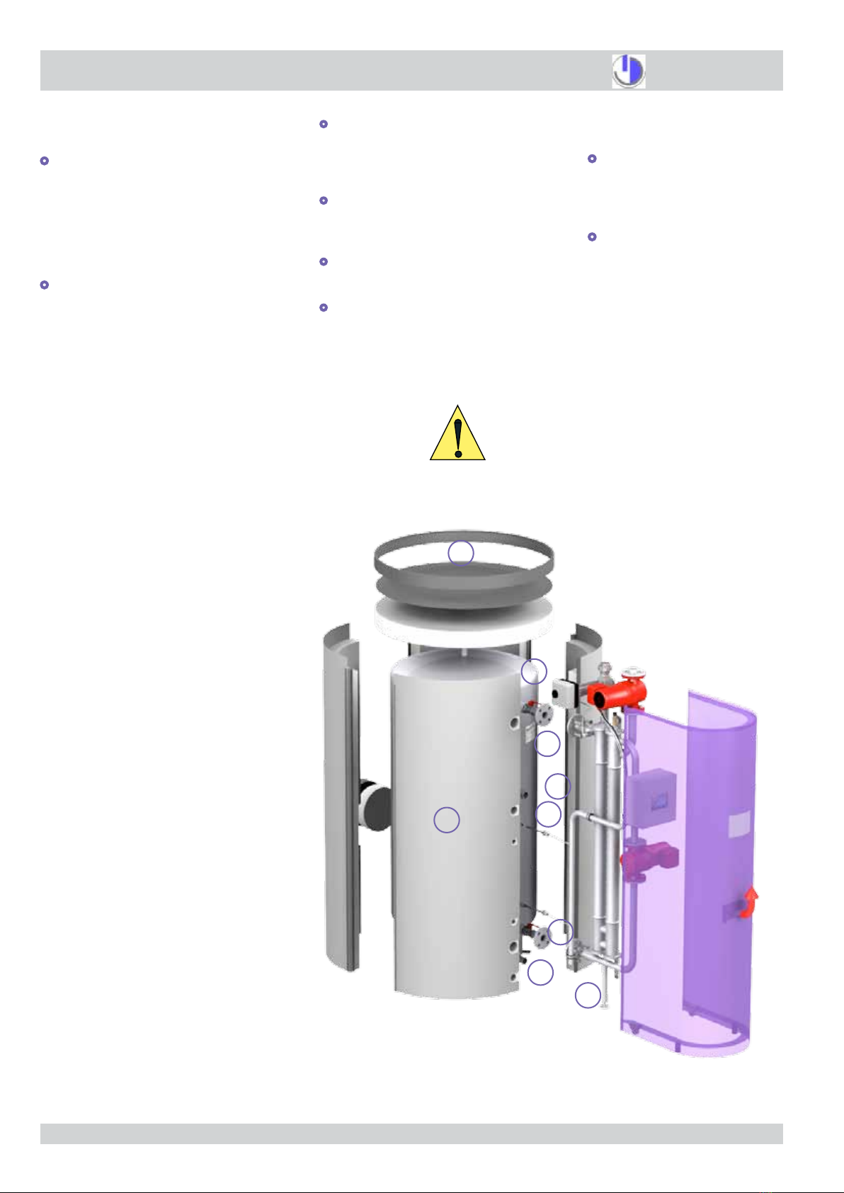
1.1.1 Unpacking storage tanks
Extreme care is required when un-
packing the pre-assembled compo-
nents from the casing. Some items
aretopheavy,andcertainparts(e.g.
microprocessorhousing)cannotbear
theweightofthepre-assemblywhen
laidsidewaysontheoor. When re-
moving storage tanks from a container,
care must be taken while clearing the
doorway not to damage or knock off
the air vent protruding from the top of
the tank.
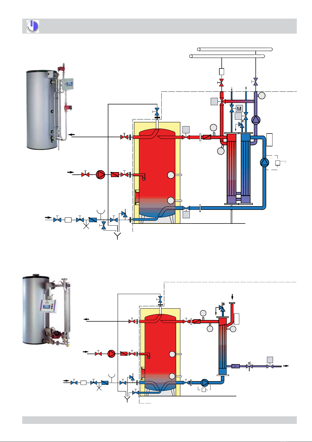
1.1.2 Non-return valves for cold
water supply and circulation con-
nections
Non-return valves must be provided
for the secondary domestic cold water
supply and circulation connections, in
order to avoid possible convectional or
expansivebackowofheatedwater.
1.1.3 Filter recommendations
To avoid damage to pumps and fouling
of heat exchangers by intake of foreign
bodies, ECOTHERM recommends
that strainers be placed in front of sup-
ply connections as follows:
Primary circuit heating water supply:
Strainer mesh size 150 - 200 µm.
Secondary circuit cold water supply:
Strainermeshsize50-60µm
1.1.4 Primary circuit heating water
pressure from boiler
The heating water supply to the heat
exchanger has minimum pressure re-
quirement of 1.5 bar, and a maximum
of 10 bar. Failure to observe this re-
quirement may potentially expose the
primary circuit to negative pressure
aeration. ECOTHERM recommends
that a closed expansion vessel with
pressurisedll-upbettedtothepri-
mary circuit.
1.1.5 Secondary circuit expansion
vessel
An expansion vessel connected to
the domestic hot water supply line is
required to allow for the increase of
water volume during heating. Failure
to observe this requirement may result
in regular small losses of heated do-
mestic water through the ECOTHERM
product‘s own pressure safety valve
during heating.
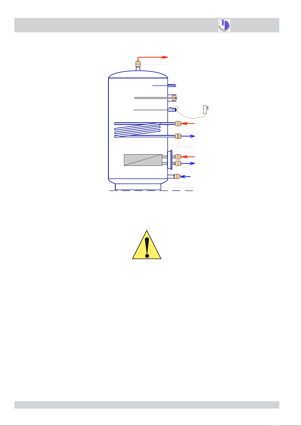
1.1.6 Tank legs
Tank legs MUST NOT be screwed or
xed to the oor under any circum-
stances, otherwise expansion strain
will cause cracks, which may lead to
leakage. The tank must be placed on
theoor,supportedbyitslegs,which
must be able to move slightly as the
tankexpandsorcontracts.(Thescrew
holes in the base of the legs are for
transportationpurposesonly.)
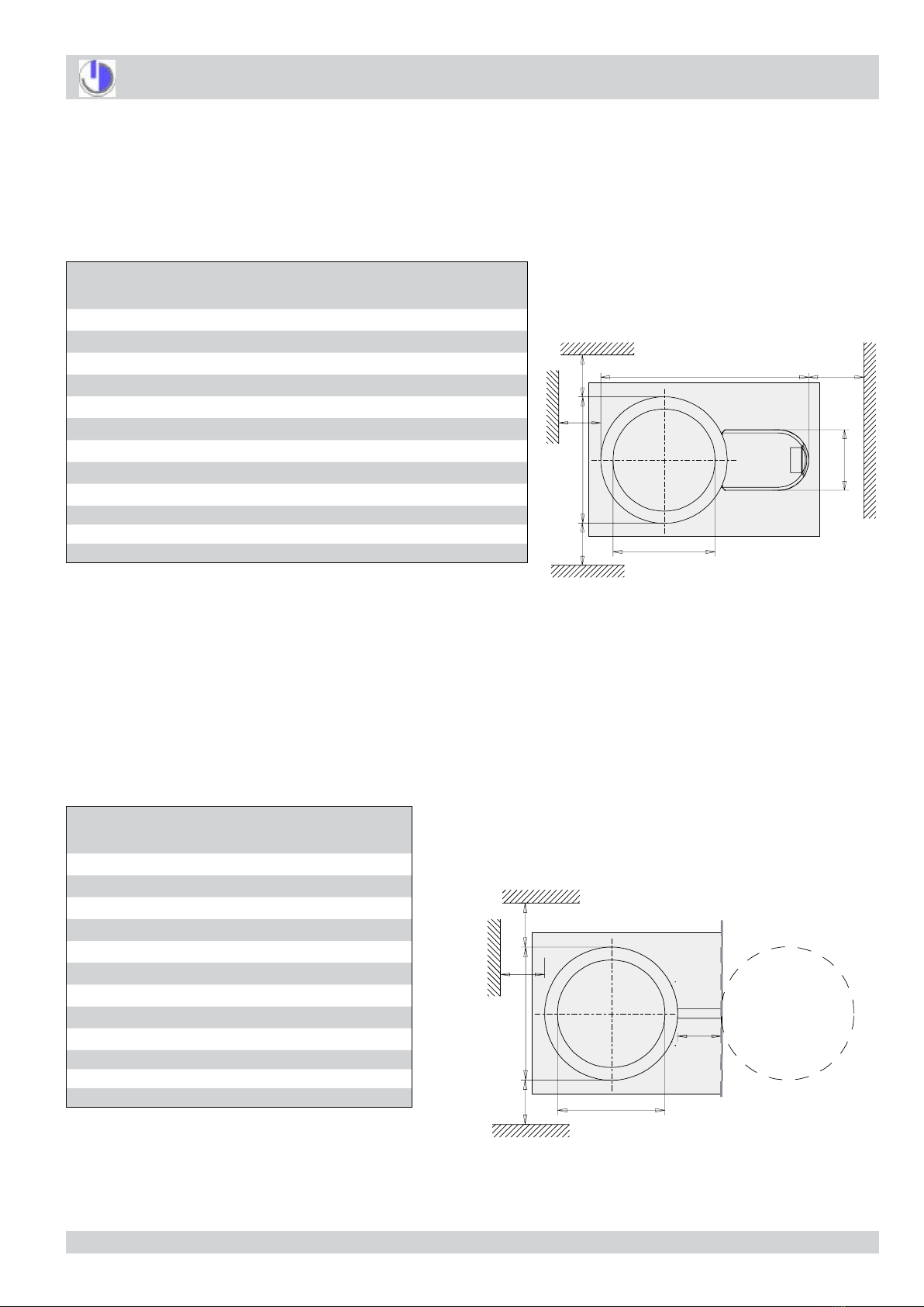
1.1.7 Electronic control unit - maxi-
mum operating temperature
Damage to electronic components
may occur if the surrounding air
temperature in the immediate vicinity
rises above 40°C. The ambient air
temperature must be low enough to
enablesufcient heat radiationcool-
ing of the high temperature electronic
components.
1.1.8 Low power electrical supply
to control unit and electric anodes
Sufcient standard household plug
sockets are to be provided within the
area of the front covers of the ECO-
THERM control unit. Rating 230V
±5%, single phase, 2.5 kVA total
power for both sockets.
1.1.9 Copper piping and water borne
chloride ions
The following applies to installations
with copper piping and water borne
chlorideions(>100mg/litre):
1.1.9a Isolating connectors
All connections must be electrically
isolated from the copper piping using
the special isolating ange kits and
isolating screw connectors provided.
1.1.9bNon-sacricialelectricanode
Thenon-sacricialelectricanodesup-
plied must be connected to the mains
power supply and be operational at
all times, in order to inhibit galvanic
transport of material away from stain-
less steel surfaces.
1.1.9c Simple repair
Please note that in the unlikely event
of pitting occurring, affected stainless
steel areas can be quickly and cheaply
repaired to 100 % serviceability on site
by your local ECOTHERM Support
Centre using specialised techniques
developed by ECOTHERM. Stainless
steel therefore offers the best possible
choice for better hygiene, durability
and longer life.