ECS ELITEGROUP DURATHON 2 User manual

Version:1.0
40-012-KU7100
Q170H4-M6

Q170H4-M6 USER MANUAL
The information in this document is subject to change without notice. The
manufacturer makes no representations or warranties with respect to the contents
hereof and specifically disclaims any implied warranties of merchantability or
fitness for any particular purpose. The manufacturer reserves the right to revise this
publication and to make changes from time to time in the content hereof without
obligation of the manufacturer to notify any person of such revision or changes.
This equipment has been tested and found to comply with the limits for a Class B
digital device, pursuant to Part 15 of the FCC Rules. These limits are designed to
provide reasonable protection against harmful interference in a residential
installation. This equipment generates, uses, and can radiate radio frequency
energy and, if not installed and used in accordance with the instructions, may cause
harmful interference to radio communications. However, there is no guarantee that
interference will not occur in a particular installation. If this equipment does cause
harmful interference to radio or television reception, which can be determined by
turning the equipment off and on, the user is encouraged to try to correct the
interference by one or more of the following measures:
•Reorient or relocate the receiving antenna
•Increase the separation between the equipment and the receiver
•Connect the equipment onto an outlet on a circuit different from that to
which the receiver is connected
•Consult the dealer or an experienced radio/TV technician for help
Shielded interconnect cables and a shielded AC power cable must be employed with
this equipment to ensure compliance with the pertinent RF emission limits
governing this device. Changes or modifications not expressly approved by the
system’s manufacturer could void the user’s authority to operate the equipment.
Federal Communications Commission (FCC)
Disclaimer
Declaration of Conformity
This device complies with part 15 of the FCC rules. Operation is subject to the follow-
ing conditions:
•This device may not cause harmful interference.
•This device must accept any interference received, including interference
that may cause undesired operation.
Limits and methods of mesurement of radio disturbance char-
acteristics of information technology equipment
EN 55022
EN 61000-3-2 Disturbances in supply systems caused
EN 61000-3-3 Disturbances in supply systems caused by household appli-
ances and similar electrical equipment “ Voltage fluctuations”
EN 55024 Information technology equipment-Immunity characteristics-
Limits and methods of measurement
EN 60950 Safety for information technology equipment including electri-
cal business equipment
CE marking
This device is in conformity with the following EC/EMC directives:

ii
Q170H4-M6 USER MANUAL
TABLE OF CONTENTS
Preface i
Brief Introduction 1
Specifications......................................................................................1
Motherboard Components................................................................3
Header Pin Definition and Jumper Settings.........................................5
I/O Ports...............................................................................................8
Multi-language Quick Installation Guide 9
English..................................................................................................9
Brazilian Portuguese..........................................................................11
Hindi....................................................................................................................13
French......................................................................................................15
Deutsch................................................................................................17
Russian................................................................................................19
Spanish................................................................................................21
Indonesian.............................................................................................23
Arabic.......................................................................................................25
Simplified Chinese...............................................................................27
Korean......................................................................................................29

Q170H4-M6 USER MANUAL
1
Brief Introduction
CPU
Specifications
•Intel
®Q170 ChipsetChipset
• Dual-channel DDR4 memory architecture
• 4 x 288-pin DDR4 Long-DIMM sockets support up to 64 GB
• Supports 2133 MHz DDR4 Long-DRAM
Memory
• 2 x PCI Express x16 slots (one slot runs x16 Gen3, the other
runs x4 Gen3)
• 1 x PCI Express x1 Gen2 slot
• 1 x PCI slot
• 1 x M.2 slot(socket 3 key M 2242/2260/2280 ) for PCIE/SATA SSD
• Supported by Intel®Q170 Express Chipset
- 4 x Serial ATA 6Gb/s devices
Expansion
Slots
Storage
• 1 x PS/2 keyboard and PS/2 mouse connectors
• 1 x VGA port
• 1 x DVI port
• 1 x HDMI port
• 1 x DP port
• 2 x USB 2.0 ports
• 4 x USB 3.0 ports
• 1 x RJ45 LAN connector
• 1 x Audio port (1x Line in, 1x Line out, 1x Mic_in Rear)
Rear Panel I/O
• Intel WGI 219LM
- 10/100/1000 Fast Ethernet Controller
- Wake-on-LAN and remote wake-up support
• LGA1151 socket for Intel®Skylake Family Processors
Note: Please go to ECS website for the latest CPU support list.
• 1 x 24-pin ATX Power Supply connector
• 1 x 4-pin 12V Power connector
• 1 x 4-pin CPU_FAN connector
• 2 x 4-pin SYS_FAN connectors
• 1 x Front Panel audio header
• 1 x Front Panel switch/LED header
• 1 x USB 3.0 header supports additional two USB 3.0 ports
• 4 x Serial ATA 6Gb/s connectors
• 2 x USB 2.0 headers support additional four USB 2.0 ports
• 2 x Serial port headers (COM)
• 1 x C-LINK header
• 1 x LPT header
• 1 x speaker header
• 1 x LDC header
• 1 x CLR_CMOS jumper
Internal I/O
Connectors &
Headers
• Realtek ALC662-VD0-GR & ALC 105 Amp
- 6 Channel High Definiton Audio Code
- Compliant with HD audio specification
Audio
LAN
Note: Please go to ECS website for the latest Menory support list.
Q170H4-M6 USER MANUAL
2
QR Code for the complete manual download
on ECS website: http://www.ecs.com.tw
• AMI BIOS with 128Mb SPI Flash ROM
- Supports Plug and Play, STR(S3)/STD(S4)
- Supports Hardware Monitor
- Supports ACPI & DMI
- Supports Audio, LAN, can be disabled in BIOS
- Supports Multi-language
- Supports Dual/Triple Display
- F7 hot key for boot up devices option
- Supports BIOS parameters copied to the flash disk
- Supports Pgup clear CMOS Hotkey (Has PS2 KB Model only)
System BIOS
Form Factor • Micro-ATX Size, 244mm x 244mm
• 1 x Mono jumper
• 1 x Case open header

Q170H4-M6 USER MANUAL
3
Motherboard Components

Q170H4-M6 USER MANUAL
4
Table of Motherboard Components
LABEL COMPONENTS
1. CPU Socket LGA1151 Skylake socket
2. CPU_FAN 4-pin CPU cooling fan connector
3. SYS_FAN 4-pin System cooling fan connector
4. DIMM_1~4 288-pin DDR4 Module slots
5. COM1~2 Onboard serial port headers
6. LPT Printer header
7. ATX_POWER Standard 24-pin ATX power connector
8. USB3F Front Panel USB 3.0 header
9. BZ Buzzer
10. SATA1~4 Serial ATA 6.0 Gb/s connectors
11. CLINK C-LINK header
12. F_PANEL Front panel switch/LED header
13. LDC Debug card header
14. F_USB1~2 Front Panel USB 2.0 headers
15. CASE Case open header
16. CLR_CMOS Clear CMOS jumper
17. SPK Speaker header
18. F_AUDIO Front panel audio header
19. MONO Mono jumper
20. PCI 32-bit add-on card slot
21. PCIEX16_1~2 PCI Express slots for graphics interface
22. PCIE1 PCI Express x1 slot
23. M.2 M.2 slot for PCIE/SATA SSD
24. ATX_12V 4-pin +12V power connector

5
Q170H4-M6 USER MANUAL
,ĞĂĚĞƌWŝŶĞĮŶŝƟŽŶĂŶĚ:ƵŵƉĞƌ^ĞƫŶŐƐ
F_AUDIO
1
9
F_USB1~2
1
1
COM
Key
PORT 1L
PORT 1R
PORT 2R
AUD_GND
AUD_GND
PRESENCE#
SENSE1_RETURN
Key
SENSE2_RETURN
KEY
NC
KEY
1
F_PANEL
Hard disk LED (-)
Hard disk LED (+)
Reset Switch (-)
Reset Switch (+)
Reserved
Power Switch (-)
Power Switch (+)
MSG LED (+)
MSG LED (-)
Ground
Power +5V
Power +5V
GroundUSB Port A (-)
USB Port B (-)
USB Port A (+)
USB Port B (+)
Serial Output
Data Carrier Detect
Serial Input
Ring Indicator
Data Terminal Ready
Clear to Send
Request to Send
Data Set Ready
Ground
PORT 2L
SPK
1
VCC Signal
Key GND
Q170H4-M6 USER MANUAL
6
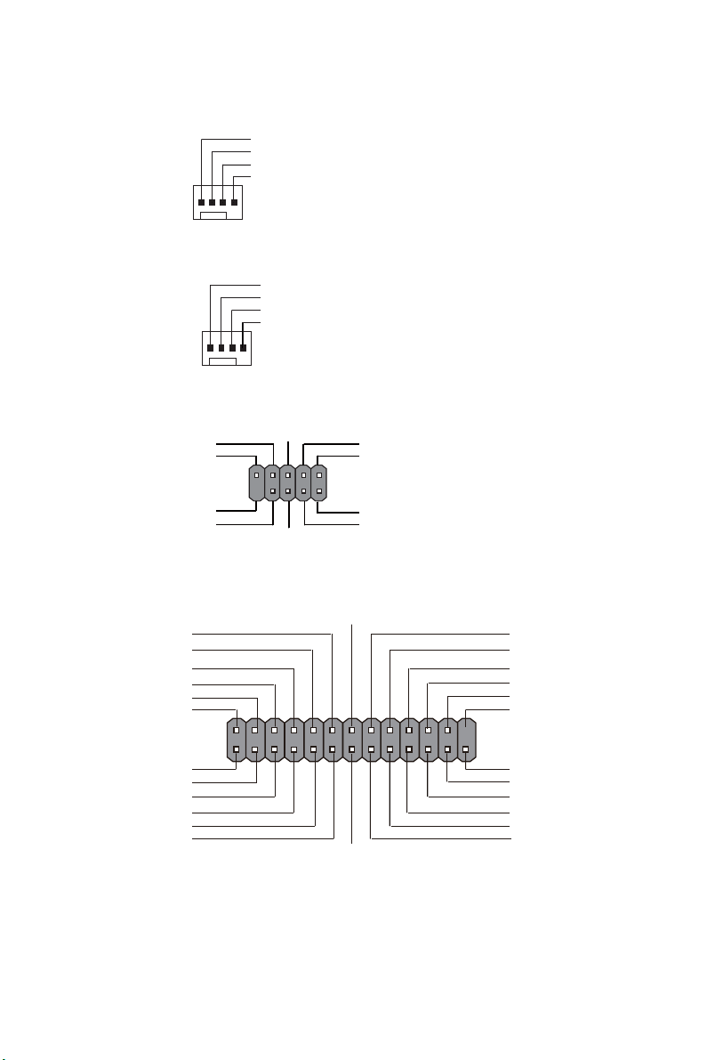
CPU_FAN
Sensor
PWM
System Ground
Power +12V
SYS_FAN
1
Sensor
PWM
System Ground
Power +12V
1
1
LDC
Clock
KEY +3.3V
LPC SignalLPC Signal
LPC Signal
LPC Signal
LPC SignalGround
Reset
LPT
1
INIT
Ground
SLCT
Ground
Key
Ground
Ground
AFD
ERROR
Ground
Ground
Ground
Ground
PD1
PD5
PD2
PD6
SLCT
PD4
PD3
STROBE
PD0
PD7
ACK
BUSK
PE

7
Q170H4-M6 USER MANUAL
CLR_CMOS Jumper
1-2: NORMAL
Before clearing the CMOS, make sure to turn off the system.
CLR_CMOS
312 2-3: CLEAR CMOS
MONO Jumper
1
1
Intruder GND
CASE
CLINK
1-2: Stereo
MONO
3
1
2
2-3: Mono
USB3F
1
Front Panel USB Power
Front Panel USB Power
Ground
Ground
USB3 ICC Port1 D+
Not Connected
Ground
Ground
USB3 ICC Port1 D-
USB3 ICC Port2 D+
USB3 ICC Port2 D-
USB3 ICC Port1 SuperSpeed Rx-
USB3 ICC Port2 SuperSpeed Rx-
USB3 ICC Port1 SuperSpeed Rx+
USB3 ICC Port2 SuperSpeed Rx+
USB3 ICC Port1 SuperSpeed Tx-
USB3 ICC Port2 SuperSpeed Tx-
USB3 ICC Port1 SuperSpeed Tx+
USB3 ICC Port2 SuperSpeed Tx+
CL_CLK
GND
CL_DATA
CL_RST
GND
GND
Q170H4-M6 USER MANUAL
8
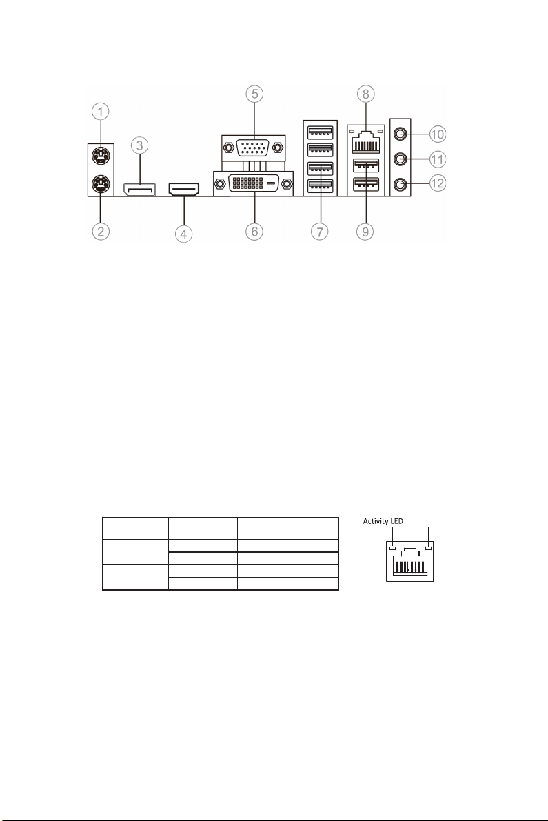
I/O Ports
1. PS/2 Mouse(green)
Use the upper PS/2 port to connect a PS/2 mouse.
2. PS/2 Keyboard(purple)
Use the lower PS/2 port to connect a PS/2 keyboard.
3. Display Port
You can connect the display device to the display port.
4. HDMI Port
You can connect the HDMI device to the HDMI port.
5. VGA Port
Connect your monitor to the VGA port.
6. DVI Port
Connect your monitor to the DVI port.
7. USB 3.0 Ports
Use the USB 3.0 ports to connect USB 3.0 devices.
8. LAN Port
Connect an RJ-45 jack to the LAN port to connect your computer to the Network.
9. USB 2.0 Ports
Use the USB 2.0 ports to connect USB 2.0 devices.
10. Line-in(blue)
It can be connected to an external CD/DVD player, Tape player or other audio
devices for audio input.
11. Line-out(lime)
It is used to connect to speakers or headphones.
12. Microphone(pink)
It is used to connect to a microphone.
LAN LED Status Description
OFF No data
Orange blinking Active
OFF No link
Green Link
Activity LED
Link LED
Link LED
LAN Port
9
English
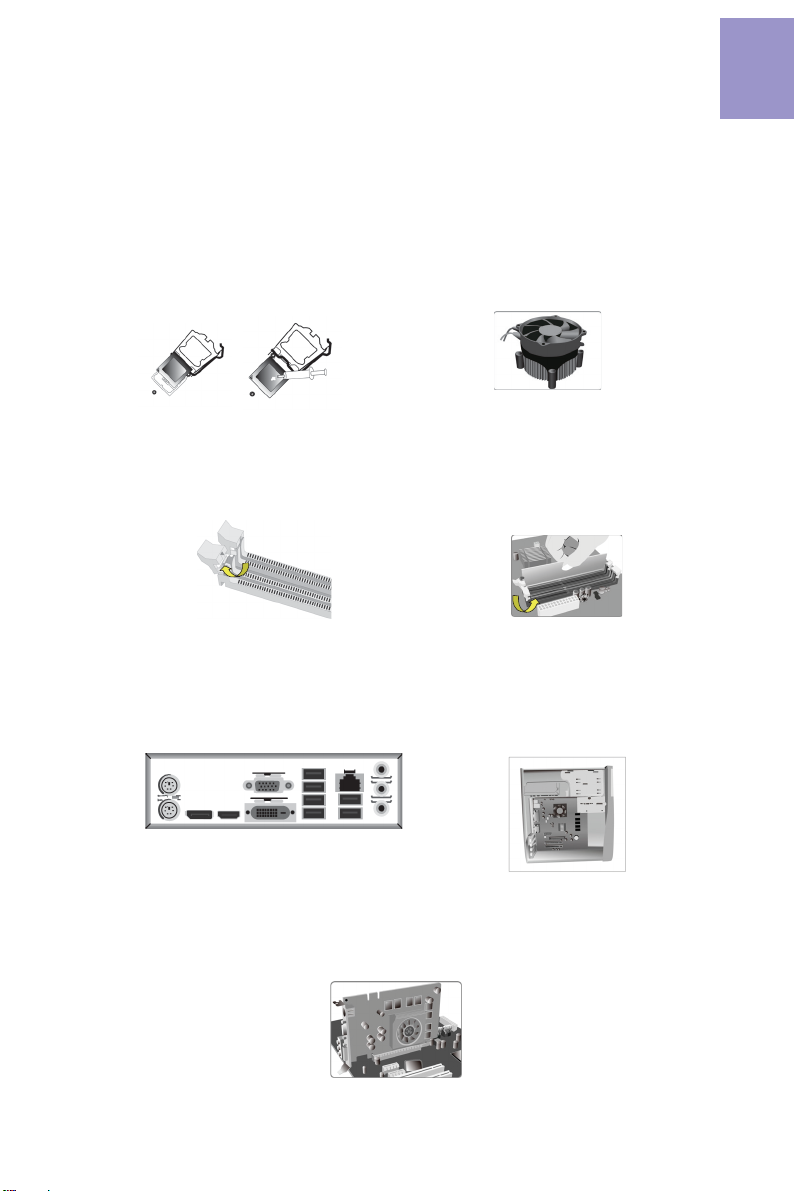
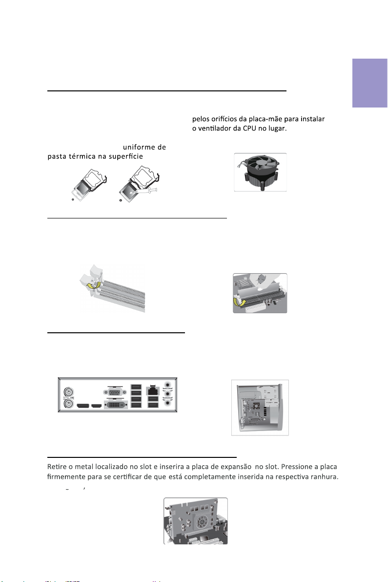
Step 1. Installation of the CPU and CPU Cooler:
Hardware Installation Guide
Installation Steps
1-1. Pull up the lever away from the
socket. Align the CPU cut edge with the
indented edge of the CPU socket.
Gently place the CPU into correct
position. Apply an even layer of thermal
grease on the surface of CPU.
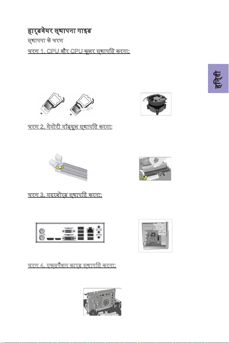
Step 2. Installation of Memory Modules:
2-1. Unfasten the latches on each side
of the DIMM slots.
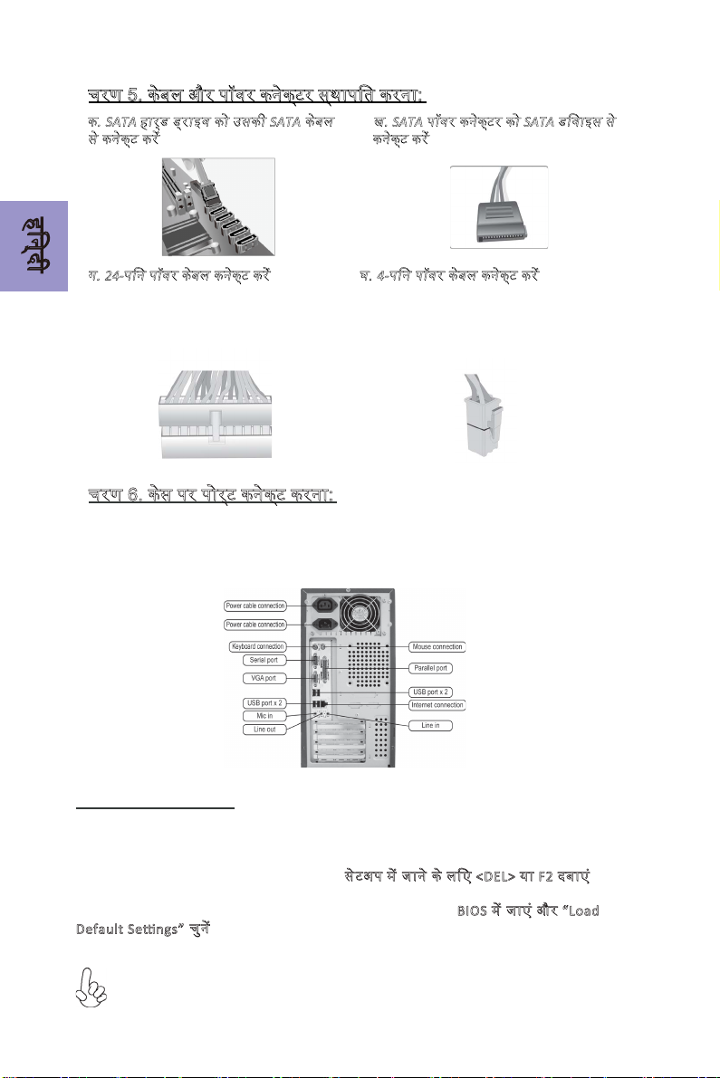
Step 3. Installation of Motherboard:
3-1. Replace the back I/O plate of the
case with the I/O shield provided in
motherboard’s package.
1-2. Rotate and press down the fastener
of CPU fan to the motherboard through
holes to install CPU fan into place.
2-2. Firmly press the DIMM down until it
seats correctly. Make sure the slot
latches are levered upwards and latch
on the edge of the DIMM.
3-2. Place the motherboard within the
case by positioning it into the I/O plate.
Secure the motherboard to the case
with screws.
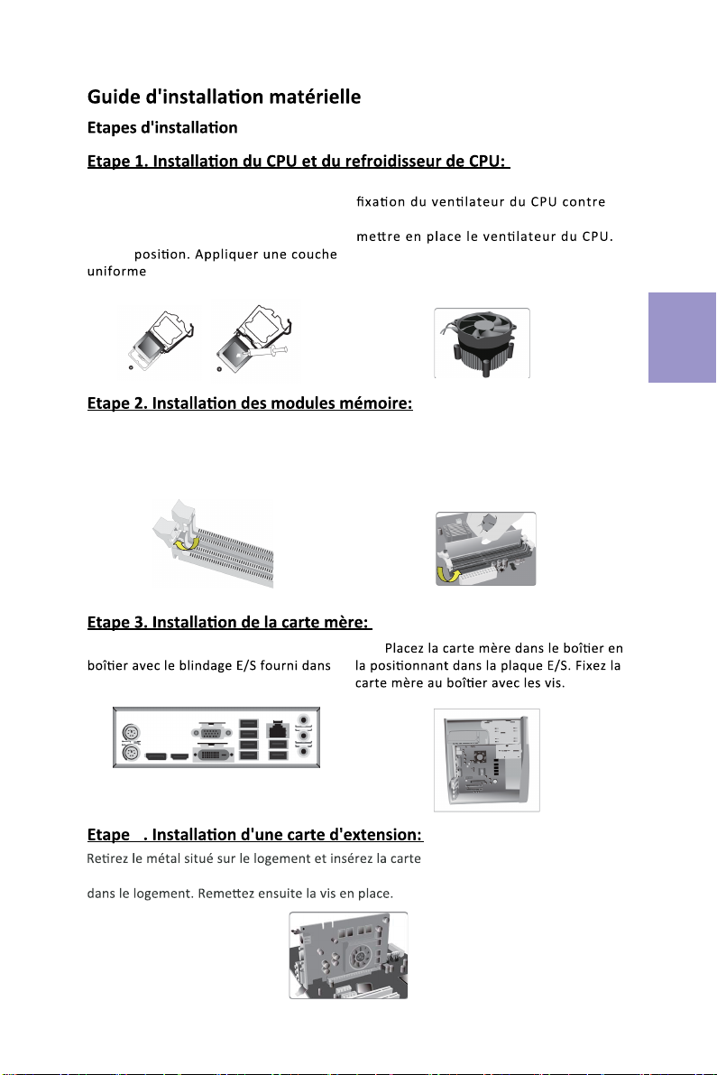
Step 4. Installation of an Expansion card:
Remove the metal located on the slot and then insert the expansion card into the
slot. Press the card firmly to make sure it is fully inserted into its slot. And then
return the screw back to its position.

10
English
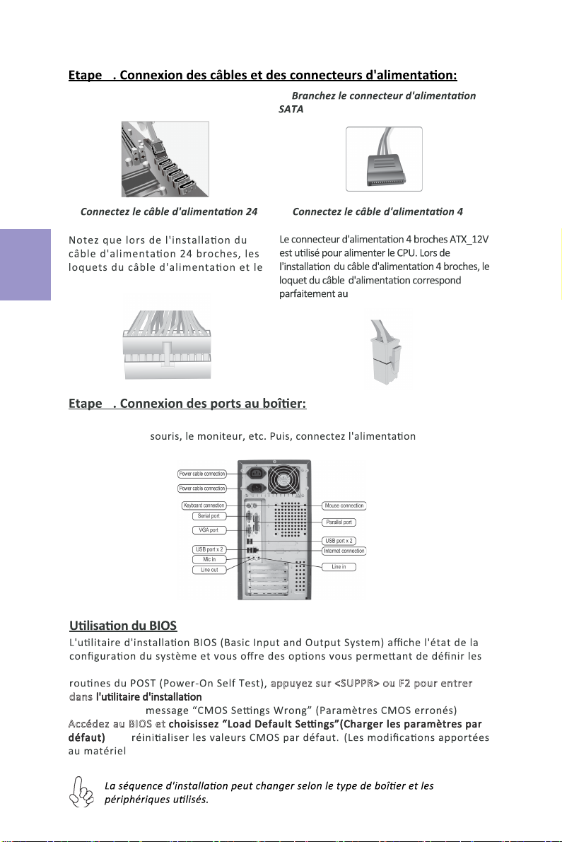
Step 5. Connecting Cables and Power Connectors:
c. Connect 24-pin power cable
The ATX_12V 4-Pin power connector is used
to provide power to the CPU. When installing
4-pin power cable, the latch of power cable
matches the ATX_12V connector perfectly.
b. Connect SATA power connector to the
SATA device
Once the steps above have been completed, please connect the peripherals such
as the keyboard, mouse, monitor, etc. Then, connect the power and turn on the
system. Please install all the required software.
Step 6: Connecting ports on the case:
a. Connect the SATA hard drive to its
SATA cable
d. Connect 4-pin power cable
Please note that when installing 24-pin
power cable, the latches of power cable
and the ATX connector match perfectly.
The sequence of installation may differ depending on the type of case and
devices used.
Using BIOS
The BIOS (Basic Input and Output System) Setup Utility displays the system’s
configuration status and provides you options to set system parameters. When
you power on the system, BIOS enters the Power-On Self Test (POST) routines,
please press <DEL> or F2 to enter setup. When powering on for the first time, the
POST screen may show a “CMOS Settings Wrong” message. Please enter BIOS and
choose “Load Default Settings” to reset the default CMOS values. (Changes to
system hardware such as different CPU, memories, etc. may also trigger this
message.)
Passo 1. Instalação da CPU e da CPU Refrigeração (Cooler):
Manual de Instalação de Hardware
Etapas para instalação
1-1. Puxe a alavanca para fora do
soquete.
Passo 2. Instalação de módulos de memória:
2-1. Solte as travas em cada lado dos
slots DIMM.
Passo 3. Instalação da Placa-mãe:
3-1. Mude a placa I/O que se encontra
no gabinete pela placa de blindagem
fornecida no pacote da placa-mãe.
Alinhe o lado da CPU com o
lado correto do soquete do
processador. Delicadamente, coloque
o processador na posição correta.
Aplique uma camada
da CPU.
2-2. Pressione Įrmemente o módulo DIMM
para baixo até queĮque corretamente
encaixado. VeriĮque se as travas do slot estão
correctamente posicionadas e travam a
extremidade do DIMM.
3-2. Coloque a placa-mãe dentro do
gabinete, posicionando-a no encaixe do
I/O. Fixe a placa-mãe ao gabinte com
parafusos.
1-2. Gire e pressione para baixo a
alavanca de fecho da ventoinha da CPU
Passo 4. Instalação de uma placa de expansão:
coloque o parafuso para sua posição de origem.
Em seguida
Português
11

Passo 5. Conexão de cabos e conectores de alimentação:
c. Ligue o cabo de alimentação 24 pinos.
O conector de alimentação ATX_12V de 4-Pin
instalar o cabo de alimentação de 4pinos, as
travas do cabo de alimentação correspondem
perfeitamente ao conector ATX_12V.
b. Ligue o conector de alimentação SATA aoa. Conecte o disco rígido SATA ao seu
cabo SATA.
d. Ligue o cabo de alimentação de 4-pinos.
Por favor note que ao instalar o cabo de
alimentação de 24 pinos, as travas do
cabo de alimentação e o conector ATX
encaixam perfeitamente.
é usado
Português
Usando a BIOS
O Programa de ConĮguração da BIOS (Sistema Básico de Entrada e Saída)
apresenta o estado da conĮguração do sistema e fornece opções para
deĮnir os parâmetros do sistema. Quando você liga o sistema, a BIOS entra nas
pressione <DEL> ou
F2 para entrar no menu d e conĮguração. Ao ligar pela primeira vez, a tela pode
mostrar a mensagem de erro POST "CMOS ConĮguração Errada". Por favor,
entre na BIOS e escolha "Carregar ConĮgurações Padrão" para repor os valores
CMOS padrão. (Alterações ao hardware do sistema, como uma CPU diferente,
memórias, etc., também podem desencadear esta mensagem.)
12
Após as etapas acima terem sido completadas, por favor conectar os periféricos como
o teclado, o mouse, monitor, etc. Em seguida, conecte a alimentação e ligue o sistema.
Por favor, instale
6
ռ֒օ&38ն֒&38շ֢֚֭֔֒և֞֟ֆշ֒֊֞
֛֭֞֒փ֧֑֗֒ ֚֭և֞֊֞ չ֞թփ
֚֭և֞֊֞շ֧ռ֒օ
1-1.֔֠֗֒շ֚֫֩շ֧ց֧ե֧֚ո֠եռշ֒
է֔չշ֧֒ե
ռ֒օ֧֫֒֠֩փ֑֢֭֚֭֔և֞֟ֆշ֒֊֞
2-1. DIMM ֚֭֔֩ցշ֭֠֒ֆ֑֧֭շ֚֞թփ֒֔չ֧
֔֨ռո֫֔ֈ֧ե
֚֩շ֧ցշ֧ֈ֞եֆ֧ֈ֧֧֚֚֞֒֟֒֟֔֞շ֒֔չ֞ձե
CPU շ֫ը֛֚֭֟ֆ֧֚֞ւ֠շվչ֛֒֎֟ւ֞ձե
CPUշ֚֠ֆ֛֒և֭֒֔չ֭֚֒֠շ֠ձշ֚֞֒
֒ֆ֔չ֞ձե
1-2. CPU շ֧եո֧շ֫ի֚շ֠վչ֛֒
֔չ֞֊֧շ֧֔֟ձCPUշ֧եո֧շ֧֍֚֭֞ց֊֒
շ֫պ֡֞ձեն֒ի֧֚ֈ֎֞շ֒ֈ֒֎֭֫֒փշ֧
ը֒֞֒շ֧ս֧ֈ֫ե֧ե֔չ֞ֈ֧ե
2-2. DIMM շ֫վ֜֎֢ֆ֧֚֠֊֠ռ֧շ֠յ֒ֈ֎֞ձեվ֎ֆշ
֛֗է֊֠վչ֛֒ւ֠շ֧֚֊֎֨ւվ֞ձ֚֡֊֭֟֘ռ֟ֆ
շ֧֒եշ֚֭֟֔֩ցշ֧֔֨ռշ֞֒֡ոլ֒շ֠յ֛֒֒ֆ֛֞֨ն֒
ի֊֛֧֭ե',00շ֧֧֚֟֒֒֔֨ռշ֑֟֞վ֞ֆ֛֞֨
ռ֒օֈ֒֎֭֫֒փ֚֭և֞֟ֆշ֒֊֞
3-1. շ֧֚շ֠֟ս֔֠ֆ֒֍֔չ֠I/O֧֭֔ցշ֫
֛ց֞շ֒ի֚շ֠վչ֛ֈ֒֎֭֫֒փշ֧֨շ֧վ֧եֈ֠
չժI/O֭֘֠֔փ֔չ֞ձե
3-2. ֈ֒֎֭֫֒փշ֫I/O֧֭֔ց֧եւ֠շֆ֛֧֚֒֎֟ւ֞շ֒
շ֧֚շ֧֏֠ֆ֒֒ո֧եֈ֒֎֭֫֒փշ֧֫ռ֧֚շ֧֧֚եշ֚ֈ֧ե
CPUշ֧֊֫շֈ֧֚֞֒֟֒շ֫CPU
13
֛֟֊֭ֈ֠
ռ֒օձշ֭֚֨ե֘֊շ֭֞֒փ֚֭և֞֟ֆշ֒֊֞
֚֭֔֩ց֒֔չ֠։֞ֆ֛֡ց֞ձեն֒֍֟֒ձշ֭֚֨ե֘֊շ֭֞֒փ֚֭֔֩ց֧ե֔չ֞ֈ֧եշ֭֞֒փշ֫վ֜֎֢ֆ֧֚֠ֈ֎֞ձե
ֆ֞շ֚֟֡֊֭֟֘ռ֟ֆ֛֚֫շ֧շ֑֛֟է֊֧֚֭֔֩ց֧եւ֠շֆ֛֧֚֒֔չչ֑֛֞֨ն֒֍֧֟֒ռշ֚֫֗֞ի֚շ֠
վչ֛֒֔չ֞ֈ֧ե
ռ֒օշ֧֎֔ն֒֩֗֒շ֊֧շ֭ց֚֭֒և֞֟ֆշ֒֊֞
չ24-֟֊֩֗֒շ֧֎֔շ֊֧շ֭ցշ֧֒ե
CPUշ֫֩֗֒ֈ֧֊֧շ֧֔֟ձATX_12V 4-֟֊֩֗֒
շ֊֧շ֭ց֒շ֞ի֑֫չշ֑֟֞վ֞ֆ֛֞֨4-֟֊֩֗֒
շ֧֎֚֭֔և֞֟ֆշ֒ֆ֧֑֚֩֗֒շ֧֎֔շ֞֔֨ռ
ATX_12Vշ֊֧շ֭ց֧֚֒֎֭֟֔շ֡֔ւ֠շ֧֧֚֔ո֞֊֞
ռ֛֞֟ձ
շSATA ֛֭֞֒փփ֭֒֞թ֗շ֫ի֚շ֠SATAշ֧֎֔
֧֚շ֊֧շ֭ցշ֧֒ե
ոSATA֩֗֒շ֊֧շ֭ց֒շ֫SATAփ֟֗֞թ֧֚֚
շ֊֧շ֭ցշ֧֒ե
պ4-֟֊֩֗֒շ֧֎֔շ֊֧շ֭ցշ֧֒ե
շ֣֑֞֊֫ցշ֧֒եշ֟24-֟֊֩֗֒շ֧֎֔
֔չ֞ֆ֧֑֚֩֗֒շ֧֎֔ն֒ATXշ֊֧շ֭ց֒
շ֧֔֨ռ֎֭֟֔շ֡֔ւ֠շ֧֧֚֔ո֞֊֧ռ֛֞֟ձ
֛֟֊֭ֈ֠
14
ի֑֭֒֡շ֭ֆռ֒օ֢֧֒շ֧֒֔֊֧շ֧֎֞ֈշ֣֑֞շ֠֎֭֫֒փ֞ի֚֩֊֠ց֒ըֈ֟վ֧֧֚֨֒֟֍֧֧֒֔շ֊֧շ֭ց
շ֧֒եի֚շ֧֎֞ֈ֩֗֒շ֊֧շ֭ցշ֧֒են֚֚֭֒֟ցռ֢֞֔շ֧֒եշ֣֑֚֞֏֠ը֑֭֗֘շ֚֩֍֭֜ց֧֑֗֒
֚֭և֞֟ֆշ֧֒ե
ռ֒օշ֧֚֭֒֫֒ցշ֊֧շ֭ցշ֒֊֞
BIOS (֎֧֚֟շթ֊֡ցն֒ըից֡ց֚֚֭֟ց֧֚ցէ֑֢ց֠֔֟ց֚֚֭֠֟ցշ֧շ֩֊֭֍֜֟չ֧֒֘֊
շ֚֭֠և֟ֆ֭֟֒ֈ֭֒֘֟ֆշ֒ֆ֛֠֨ն֒ըշ֚֚֭֫֟ցշ֧֨֒֞֠ց֧֚֒ցշ֒֊֧շ֧֗֟շ֭֔
ի֔֎֭։շ֒֞ֆ֛֠֨վ֎ը֚֚֭֟ցշ֠֩֗֒ճ֊շ֒ֆ֧֛֨եֆ֫BIOS֩֗֒ճ֊֧֚֭֔֍֜
ց֧֚֭ց(POST)֢֒ց֠֊֧ե֧֭֒֗֘շ֒ֆ֛֞֨շ֣֑֞
֛֔֠֎֞֒֩֗֒ռ֢֞֔շ֟ձվ֞֊֧֒POST֚֭շ֭֒֠֊DK^^ĞƫŶŐƐtƌŽŶŐ֚եֈ֧֘
ֈ֟ո֚֞շֆ֛֠֨փ֟֍֭֜֩֔ցCMOS֑֢֧֭֚֗֨֔֒֠ցշ֒֊֧շ֧֔֟ձշ֣֑֞
֏֟֊֭֊CPU֧֫֒֠ըֈ֟վ֧֚֚֚֭֨֟ց֛֭֞֒փ֧֑֧֗֒ե֎ֈ֔֞֗շ֒֊֧
֒֏֑֛֚֠եֈ֧֘ը֚շֆ֛֞֨
%,26շ֞ի֑֫չշ֒֊֞
շ֧֚շ֧֭֒շ֞֒ն֒ի֑֫չշ֠վ֞֊֧֗֞֔֠փ֟֗֞թ֚շ֧է֊֚֚֭֡֞֒և֞֊֞շ֞շ֭֒
է֔չէ֔չ֛֚֫շֆ֛֞֨
ĞĨĂƵůƚ^ĞƫŶŐƐռ֡֊֧ե
BIOS ֧ե վ֞ձեն֒>ŽĂĚ
֧֚ցէ ֧ե վ֞֊֧շ֧ ֔֟ձ <DEL> ֑֞ F2 ֈ֎֞ձե
1-1. Ecartez le levier du socket.
2-1. Libérez les loquets de chaque côté
des logements DIMM.
3-1. Replacez la plaque E/S arrière du
l’emballage de la carte mère.
Alignez
le bord coupé du CPU avec le bord
correspondant sur le socket du CPU.
Placez soigneusement le CPU dans la
bonne
de pâte thermique sur la
surface du CPU.
1-2. Tournez et appuyez sur la
2-2. Pressez fermement le module DIMM
jusqu'à ce qu'il soit correctement installé.
Assurez-vous que les loquets des logements
sont soulevés et accrochés sur le bord de la
DIMM.
3-2.
la
carte mère à travers les trous pour
Français
d'extension dans le logement.
Appuyez fermement sur la carte pour vous assurer qu'elle est complètement insérée
4
15
c.
broches
connecteur ATX_12V.
b.
au périphérique SATA
a. Connectez le disque dur SATA à son
câble SATA
d.
broches
connecteur ATX correspondent
parfaitement.
Français
16
5
Une fois que les étapes ci-dessus ont été eīectuées, connectez les périphériques tels
que le clavier, la et allumez le
système. Installez tous les logiciels requis.
6
paramètres du système. Quand vous allumez le système, le BIOS entre dans les
appuyez sur <SUPPR> ou F2pour entrer
dans . Lors de la première mise sous tension, l'écran du POST
peut aĸcher le
Accédez au BIOS et
pour
du système tels que diīérents CPU, mémoires, etc. peuvent également
déclencher ce message.)

1-1. Lösen Sie den Hebel vom
CPU-Sockel.
2-1. Lösen Sie die Verriegelungen an
beiden Seiten der DIMM-Steckplätze.
Kunststoīabdeckung und richten Sie die
Kerbe der CPU mit der entsprechenden
Stelle des CPU-Sockels aus. Legen Sie die
Tragen Sie eine erbsengroße Menge der
OberŇäche der CPU auf.
2-2. Drücken Sie das DIMM-Speichermodul
sitzt. Drücken Sie die Verriegelungen an den
Seiten des Speichermoduls nach oben und
prüfen Sie, ob diese im DIMM-Speichermodul
ATX-Blende (I/O-Schild) des Gehäuses
und verwenden Sie die ATX-Blende, die
wurde.
3-2. Richten Sie die Anschlussseite der
der
ATX-Blende im Gehäuse aus und
mit den Schrauben am
Gehäuse.
Deutsch
17
1-2. Lösen Sie durch eine Drehung die Pushpins
des CPU-Kühlers und richten Sie diese mit den
entsprechenden Löchern
aus und drücken Sie die
Pushpins nach unten bis sie einrasten.
Metall hinten am Gehäuse, wo der
zu verwendende Steckplatz sicŚďĞĮŶĚet und stecken Sie die Erweiterungskarte in den
Steckplatz. Prüfen Sie ob die Kontakte der Erweiterungskarte
die Erweiterungskarte mit der Schraube mit der die
Other manuals for DURATHON 2
1
This manual suits for next models
1
Table of contents
Languages:
Other ECS ELITEGROUP Motherboard manuals


