ECS PGEN-20 User manual

Specifications
Dimensions:
Weight:
Temperature Range:
Compressor Power Supply:
Power Consumption:
Generator Power Supply:
Power Consumption:
Nitrogen/Air Connection:
Drain Connection:
Approvals:
32” (W) x 57” (H) x 40” (D)
813mm (W) x 1,448 (H) x 1,016mm (D)
425 Lbs (193 Kg)
40°F - 105°F (5°C - 40°C)
PGEN-20 - 480VAC/3 phase/60Hz (Standard)
PGEN-20 - 208VAC/3 phase/60Hz (Optional)
PGEN-20E - 400VAC/3 phase/50Hz
Dedicated circuit for the 2 hp compressor
480VAC/3 phase/60Hz - 6 Amps
208VAC/3 phase/60Hz - 9 Amps
(400VAC/3 phase/50Hz - 12 Amps)
120VAC/1 phase/60Hz (dedicated circuit)
220-240VAC/1 phase/50Hz (dedicated circuit)
2 Amps
½” NPT Female
½” NPT Male
FM Approved
CE Certified
UL508A Listed Industrial Control Panel
Ordering Information
Stock Number:
Replacement Filters:
Gas Membrane:
PGEN-20(E)
PGEN-FKS-F (annual maintenance)
PGEN-MS (20 year expected service life)
General Description
Rev 81
ECS Pre-Engineered Nitrogen Generator
PGEN-20 (20E)
Engineered Corrosion Solutions •11336 Lackland Road St. Louis, MO 63146 •Phone: 314.432.1377 •www.ecscorrosion.com
For use under U.S. Patents
8,720,591, 9,144,700 and 9,186,533
The ECS Pre-Engineered Skid Mount Nitrogen Generator is designed to facilitate the Dry Pipe Nitrogen Inerting
(DPNI) process for controlling oxygen corrosion in dry pipe and preaction fire sprinkler systems with supervisory
nitrogen maintenance gas. The nitrogen generator can be used in cold storage/freezer applications due to
added benefit of ice plug mitigation. With plug and play performance in a typical dry pipe or preaction fire sprinkler
system, the nitrogen generator utilizes membrane separation technology that produces 98%+ nitrogen gas on
demand.
The ECS Nitrogen Generator supplies single or multiple sprinkler systems depending on the number of systems,
the volume of the largest system, and the cumulative volume of all systems being supplied. The generator includes
an integral air compressor and external bypass valve for maintenance or for “fast fill” needs to meet the NFPA 13
30-minute fill requirement for dry pipe and preaction fire protection systems. Cold storage application requirements
vary based on the temperature of refrigerated space - contact ECS for design assistance.
The ECS Nitrogen Generator is designed to inert the supervised sprinkler system within 14 days and then
automatically provide nitrogen gas for pressure maintenance. When paired with either the Protector Dry Manual
Vent (PAV-D) or the Protector Dry SMART Vent (PSV-D/DE) installed on the sprinkler riser, the nitrogen
generator facilitates the patented “fill and purge” breathing process to remove all the corrosive oxygen gas in
the sprinkler systems without the need for nitrogen storage.

NOTE:
When connecting an ECS Protector Nitrogen Generator to an existing dry pipe/preaction fire sprinkler system, the
existing fire sprinkler system(s) must be limited to a maximum leak rate of less than 6 psig (.4 bar) within a 24 hour
period, per system.
Nitrogen Quality
98% or greater (maximum of 2.0% oxygen)
Min of 15 psig (1 bar); Max of feed air pressure minus 15 psig (1 bar)
Typically less than -70˚F (-57˚C)
N2Purity at Discharge:
N2Pressure at Discharge:
N2Water Dew Point:
Operating Performance
PGEN-20/(20E) 10 (283) 3, 20 0 (12,113) 950 (3,596) 1,800 (6,814)
Model
Number
Min. Supply Air
SCFM (L/min)
Total System Capacity
Gallons (Liters)
Single System Capacity †
@ 40 psig (2.8 bar)
Gallons (Liters)
Single System Capacity †
@ 20 psig (1.4 bar)
Gallons (Liters)
Sound Level
dBA @ 10’
† Capacity based on NFPA 13 30-minute fill requirement of largest single system
74
Rev 82
Engineered Corrosion Solutions •11336 Lackland Road St. Louis, MO 63146 •Phone: 314.432.1377 •www.ecscorrosion.com
The ECS Pre-Engineered Nitrogen Generator is a self-contained skid mounted unit that includes the
following components:
• 2 hp air compressor power supply
• 480VAC/3 phase/60Hz (400VAC/3 phase/50Hz) - Standard
• 208VAC/3 phase/60Hz - Optional
• Oil less air compressor with after cooler
• 20 gallon horizontal air receiver tank with automatic condensate blow down – ½” NPT Male
• Steel enclosure cabinet with membrane type nitrogen generator (no nitrogen gas storage) and manual
bypass
• Power supply - 120VAC/1 phase/60Hz (220-240VAC/1 phase/50Hz)
• Single point nitrogen/air discharge – ½” NPT Female
• Hour run meter and cycle counter
The ECS Nitrogen Generator includes the following function Indications:
• Bypass Alarm - Nitrogen generator is in the “By-Pass” mode (Flashing Indicator)
• Leak Monitoring - Nitrogen generator running excessively (Audible Signal)
The ECS Nitrogen Generator includes the following monitoring outputs:
• System Power (Digital Output)
• Bypass Mode Alarm (Digital Output)
• Nitrogen Generator Running (Digital Output)
• Leak Monitoring (Digital Output)
• Nitrogen Supply Line Pressure (Analog Output)
The ECS Nitrogen Generator is designed to be used in conjunction with the following components as part
of the complete ECS Dry Pipe Nitrogen Inerting (DPNI) system:
• Air maintenance device with on board adjustable regulator (recommend Victaulic Series 757; Tyco AMD-1
or; Reliable Model A)
NOTE: The air maintenance device is not required when the PGEN-3 or PGEN-5 is connected to a single
dry pipe or pre-action sprinkler system.
• Riser-mounted ECS Protector Manual Vent (PAV-D) or ECS Protector Dry SMART Vent (PSV-D/DE)
The ECS Nitrogen Generator can be used with the following optional equipment:
• ECS Protector SMART Gas Analyzer (SGA-1) - one per nitrogen generator is recommended
• ECS In-Line Corrosion Detector (ILD-X) - monitoring at least one per sprinkler system is recommended
ECS Pre-Engineered Nitrogen Generator
PGEN-20 (20E)

Installation Instructions
Installation of the ECS Protector Nitrogen Generator requires five (5) steps:
1. Mount the ECS Nitrogen Generator skid to the floor in the appropriate location within the riser room
2. Connect the two (2) dedicated power supply circuits in the power supply cabinet on the skid
3. Plumb the nitrogen/air supply line to the water based fire sprinkler risers being served
4. Plumb the condensate drain line to floor drain or building exterior
5. Connect Nitrogen generator output signals to BMS or fire alarm system, where applicable
Step 1: Mounting the Skid
Step 2: Power Supply
The nitrogen generator requires two dedicated power supply circuits. Both circuits connect to the terminal
blocks inside the power supply box.
The ECS Nitrogen Generator is designed to be mounted directly to the floor in the fire sprinkler riser room.
Several factors should be considered in choosing the proper mounting location for the nitrogen generator:
• Access to the power supply (dedicated circuits)
• Access to the sprinkler risers being supplied from the nitrogen generator
• Access to a drain for the condensate discharge line
• Clearance at the front of the unit to open the cabinet door
• Clearance from the side of the unit to access the power box
The skid base comes with pre-punched holes in the skid feet for easy mounting to the floor using standard
anchors. The anchors can be tightened through the pre-punched access holes located at the corners of
the skid.
57” (1,448mm)
With Cabinet Door
Open
40” (1,016mm)
32” (813mm)
Pre-Punched Holes
for Mounting
1. 2 hp compressor power supply
2. Nitrogen generator power supply
480VAC/3 phase/60Hz dedicated 20 amp circuit (Standard)
208VAC/3 phase/60Hz dedicated 20 amp circuit (Optional)
(400VAC/3 phase/50Hz dedicated 20 amp circuit)
120VAC/1 phase/60Hz dedicated 20 amp circuit
(220-240VAC/1 phase/50Hz dedicated 20 amp circuit)
Rev 83
Engineered Corrosion Solutions •11336 Lackland Road St. Louis, MO 63146 •Phone: 314.432.1377 •www.ecscorrosion.com
ECS Pre-Engineered Nitrogen Generator
PGEN-20 (20E)

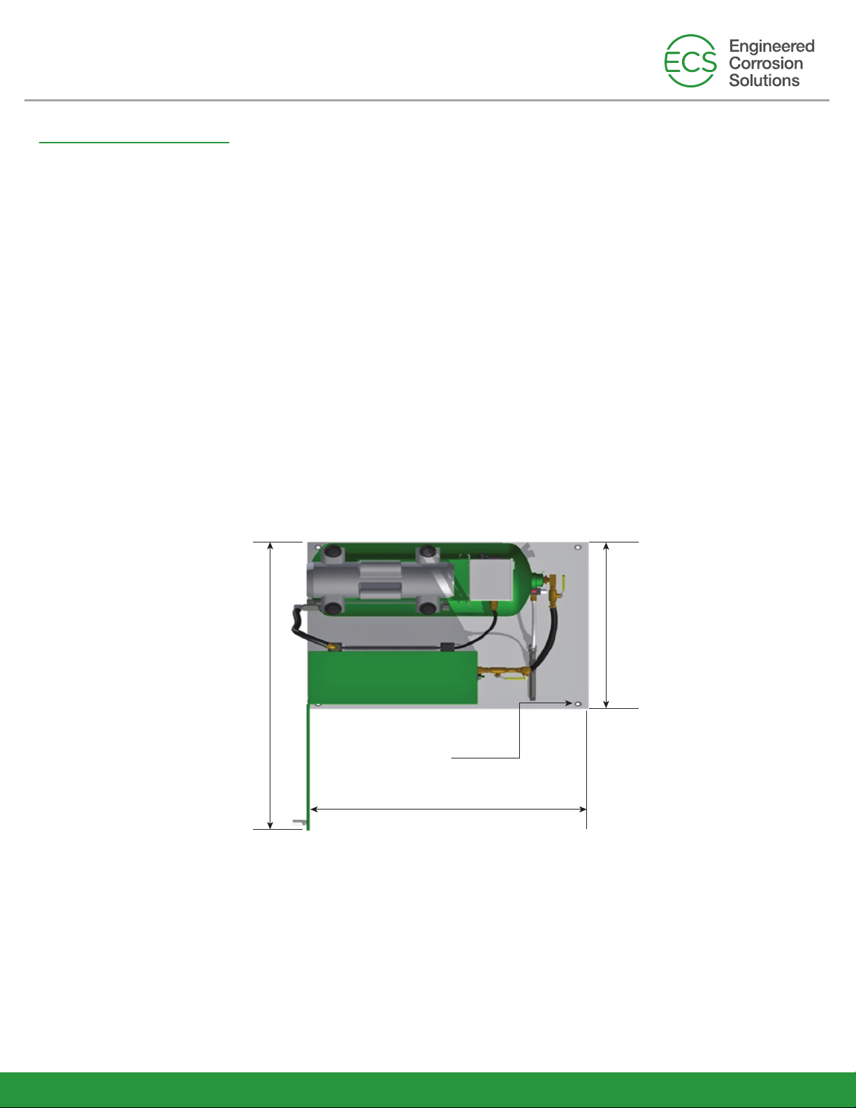
Step 3: Plumb the Nitrogen/Air Supply Line
The nitrogen/air discharge plumbing from the ECS Protector Nitrogen Generator is to be connected directly
to the sprinkler system valve trim using ½” to 1” black steel, galvanized steel, or copper piping. The size of
the nitrogen/air supply line shall be based on both the length of pipe between the nitrogen generator and
fire sprinkler systems and the total volume of fire sprinkler systems being supplied. The nitrogen generator
requires an in-line Air Maintenance Device (AMD) that is equipped with an on board field adjust able
pressure regulator for each zone being served. The preferred AMD is the Victaulic Series 757.
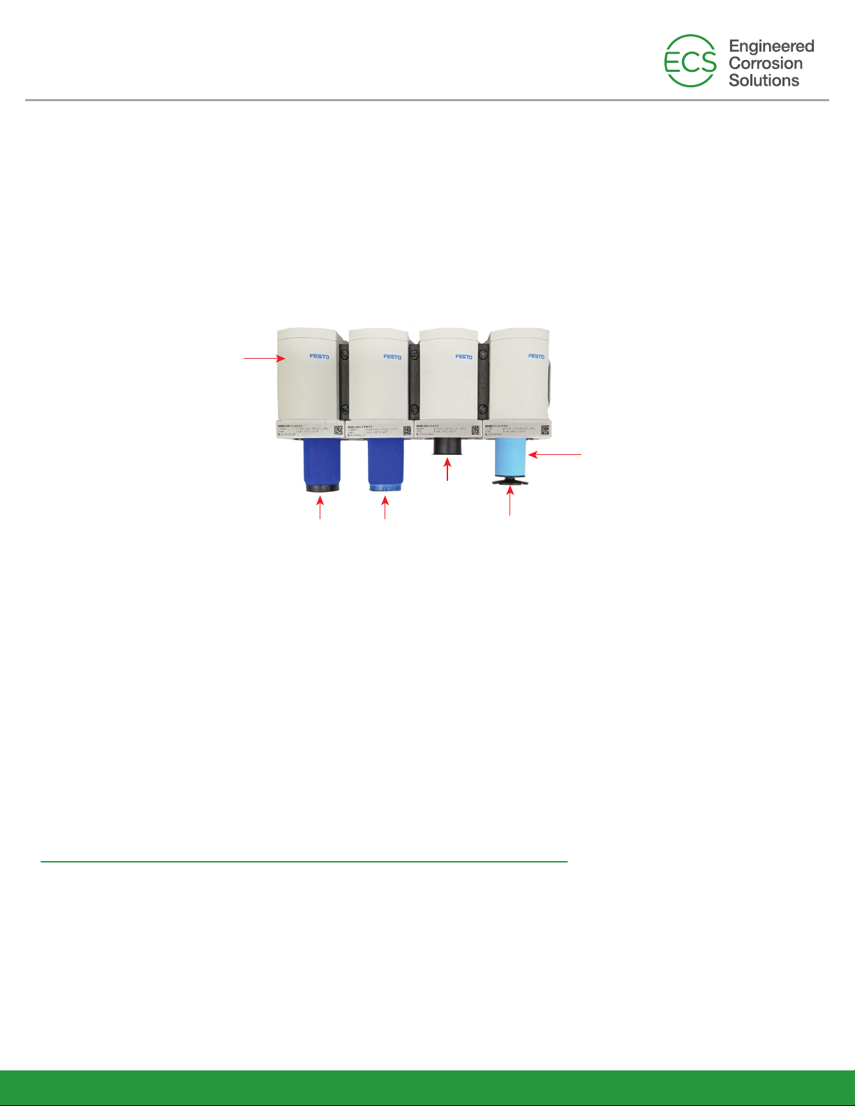
Step 4: Plumb the Condensate Drain Line
The ECS Protector Nitrogen Generator will occasionally discharge a small amount of condensate water
from the coalescing filters inside the cabinet and the air compressor tank. It is recommended that the ½”
drain connection be plumbed to a floor drain or building exterior. When plumbing to a drain is not feasible
an evaporative collection chamber can be used.
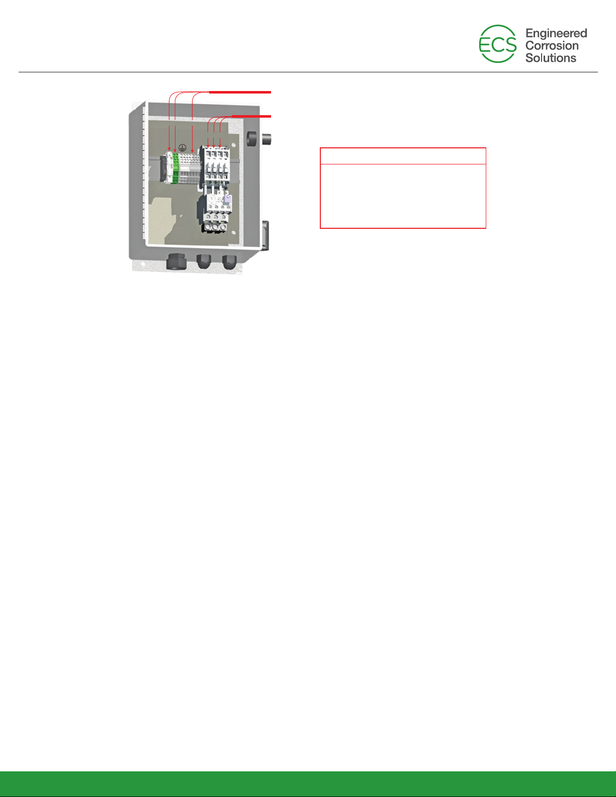
When providing 208VAC/3 phase/60Hz
to the control box, verify the
compressor and the motor starter have
been reconfigured for operating at
208VAC/3 phase/60Hz
NOTE:
L1 G N
120VAC/1 Phase 60Hz Connections
(220-240VAC/1 Phase 50Hz Connections)
480VAC/3 phase/60Hz Connections
208VAC/3 phase/60Hz Connections
(400VAC/3 phase/50Hz Connections)
L1 L2 L3
Rev 84
Engineered Corrosion Solutions •11336 Lackland Road St. Louis, MO 63146 •Phone: 314.432.1377 •www.ecscorrosion.com
NOTE: When both dry pipe and preaction fire sprinkler systems are connected to one nitrogen generator, additional
equipment may be required if the fire sprinkler systems operate at different supervisory gas pressures.
Step 5: System Signals and Monitoring, where used
The nitrogen generator cabinet has two (2) system signals and five (5) outputs that can be monitored by
the facility’s BMS or fire alarm system.
• Bypass Alarm - The nitrogen generator is operating in the bypass mode which is activated when
the bypass valve is in the “fast fill” position to fast fill the fire sprinkler system and the air supplied
directly from the air compressor has reached a pressure of 20 psig (1.4 bar).
(Flashing amber light)
• Leak Monitor - The nitrogen generator is equipped with a leak monitor audible signal which is
activated when the nitrogen generator runs excessively. (Audible signal)
The nitrogen generator cabinet includes system monitoring signals which can be monitored through a
building monitoring system, if desired:
• Nitrogen Generator Running - Form C contacts
• Bypass Mode Alarm - Form C contacts
• Nitrogen Generator Power Monitoring - Form C contacts
• Leak Monitoring - Form C contacts
• Nitrogen System Supply Line Pressure - Analog Signal
ECS Pre-Engineered Nitrogen Generator
PGEN-20 (20E)

Nitrogen
Generator
Nitrogen/Air
Supply Line
ECS Protector Dry Pipe
Venting Device
Dry Pipe/Preaction
System Control Valve
ECS Protector SMART
Control Cabinet
Rev 85
Engineered Corrosion Solutions •11336 Lackland Road St. Louis, MO 63146 •Phone: 314.432.1377 •www.ecscorrosion.com
ECS Pre-Engineered Nitrogen
Generation System
(typical installation schematic)
Preliminary Steps (taking the nitrogen generator out of service)
1. Turn the power supply to the unit off
2. Close the inlet and outlet ball valves, and open the bypass ball valve
3. Depressurize the nitrogen generator internal inlet piping by slowly opening the depressurization valve
in the cabinet to the left of the filter housing
Filter Replacement Procedure
Maintenance of the Nitrogen Generator:
The nitrogen generator cabinet contains three (3) separate cartridge filters and a water separator. It is
recommended that each of the filter cartridges be replaced as part of an annual preventative
maintenance program. In some environments it may be necessary to replace filters more frequently. The filter
replacement kit for the nitrogen generator is part number PGEN-FKS-F. When maintained properly the nitrogen
separation membrane will provide up to 20 years of service life.
To replace the filter cartridges follow Step 1 through Step 7.
Filter Housing
Clear Drain Tubes
Depressurization
Ball Valve
BMS Mon. Pts.
Generator Running
Bypass Mode
Power On/Off
Leak Monitor
N.C. N.C. N.C. N.C.
N.O. N.O. N.O. N.O.
C C C C
L1 N N G G
Power
Supply
Pressure Switch
Incoming Power Fuse Block
N.C.
N.O.
C
N
Nitrogen Generator
Running Output
By-Pass Alarm
Monitoring Output
Nitrogen Generator
Power Monitoring Output
Leak Monitoring Output
Nitrogen System Supply Line Pressure
(Analog Signal)
ECS Pre-Engineered Nitrogen Generator
PGEN-20 (20E)

Rev 86
Engineered Corrosion Solutions •11336 Lackland Road St. Louis, MO 63146 •Phone: 314.432.1377 •www.ecscorrosion.com
Filter
Cartridge
#1
Top of Filter
Housing
Filter
Cartridge
#3
Black Disc
Filter
Cartridge
#2
Water
Separator
1. Turn the power supply to the unit on
2. Open the inlet and outlet ball valves, and close the bypass valve on the bypass loop.
3. Check inside the nitrogen generator cabinet for leaks using a soap water solution. Tighten fittings where needed.
ECS Protector Nitrogen Generator Optional Monitoring Equipment
Return the Nitrogen Generator to Service
• ECS Protector Handheld Gas Analyzer (PHGA-1): portable handheld gas analyzer includes one-button
calibration and enables user to measure nitrogen concentration at nitrogen generator cabinet or gas sampling
ports on ECS oxygen removal vents.
• ECS Protector SMART Gas Analyzer (SGA-1): permanently installed near an ECS Protector Manual/ SMART
Vent to continuously report nitrogen gas concentration to a building information or management system;
includes digital display and provides 0-5V DC or 4-20mA output signals.
• ECS In-Line Corrosion Detector (ILD-X): installed in-line within the fire sprinkler system piping at locations
most susceptible to corrosion; provides either a local push-button test/indicator or control panel monitoring.
Step 1: Remove the filter housing by pulling down on the blue housing lock and turning the filter housing
counter-clock wise.
Step 2: Once the filter housing has been removed, the filter cartridge inside is removed by first unscrewing the
black retaining disc at the base of the cartridge and then pulling down on the cartridge. Discard the old
filter cartridge and replace it with the appropriately marked filter cartridge from the filter replacement kit
by pushing up so that it fits snugly onto the receiving cylinder in the upper part of the filter housing. Screw
the black retaining disc back onto the threaded rod.
Important: HAND TIGHTEN ONLY!
Step 3: Replace the filter housing by pushing up into position and turning housing clockwise until blue housing lock
latches into place.
Step 4: Repeat Step 1 through Step 3 for each additional filter. (NOTE: Filters 2 & 3 do not have a black retaining
disc, filters screw directly into housing)
Step 5: Remove water separator housing and inspect water separator. Clean as necessary
Step 6: Close the depressurization ball valve.
Step 7: The ECS Protector Nitrogen Generator can now be placed back into service.
ECS Pre-Engineered Nitrogen Generator
PGEN-20 (20E)
Table of contents
Other ECS Portable Generator manuals
Popular Portable Generator manuals by other brands

Global Machinery Company
Global Machinery Company GEN instruction manual

Black Max
Black Max BM905530 Operator's manual

MULTIQUIP
MULTIQUIP Power Ultra-Silent DCA-45USI Operation and parts manual

Champion Global Power Equipment
Champion Global Power Equipment 500110-N Owner's manual & operating instructions

Robin America
Robin America Bannerman EC17D parts manual

AQ-Tron
AQ-Tron BAT/44892 product manual