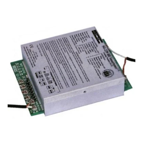
ECU Master TUNER3 User manual

DIGITAL ECU TUNER 3 – User Manual
Page 1
www.ecumaster.com

DIGITAL ECU TUNER 3 – User Manual
Attention!
Digital ECU Tuner 3 can be used only for motor sports and cannot be used on public
roads!
The installation of the de ice can be conducted only by trained specialists. The
installation performed by an unskilled person may lead to the damage of both the de ice
and the engine!
Incorrect tuning of the engine with Digital ECU Tuner 3 (DET3) can result in a serious
damage of your ehicle!
Ne er modify the de ice’s settings when the car is mo ing because it may cause an
accident!
Ecumaster is not responsible for the damages caused by an incorrect installation or/ and
tuning of the de ice!
Important !
The manual below refers to the 1.0 (HW Version 1.0) ersion of the Digital ECU Tuner 3
(DET3).
Modification of the tables should be conducted only by people who understand the
working rules of the de ice and working rules of the modern injection and ignition
systems.
Always use the AFR meter during the modification of fuel settings.
Ne er short-circuit the lines of the engine’s wiring loom as well as the outputs of the
DET3 de ice.
All modifications of the engine’s wiring loom as well as of the DET3 de ice must be
performed with the unplugged negati e terminal of the battery.
It is important for the quality of the joints of the wiring loom links to be high and to be
correctly insulated.
The connection wires should not be longer than 30 cm.
All signals from the ariable reluctant sensors should be connected by using shielded
cables.
E ery unused input should be connected to the Ground.
The de ice must be disconnected during welding of any car body elements,!
Page 2
www.ecumaster.com

DIGITAL ECU TUNER 3 – User Manual
Table of content
Digital ECU Tuner 3 .......................................................................................................................................................................4
Minimal PC configuration................................................................................................................................................................5
Firmware's update............................................................................................................................................................................6
Connector pin data ..........................................................................................................................................................................7
Software installation.........................................................................................................................................................................8
Toolbar.............................................................................................................................................................................................9
Tables.............................................................................................................................................................................................10
Analog Inputs.................................................................................................................................................................................15
Analog output (Analog Out).........................................................................................................................................................17
Controlling ignition angle..............................................................................................................................................................18
Power outputs: Power Out #1 i Power Out #2..............................................................................................................................25
Parametric Output..........................................................................................................................................................................29
Modification of frequency signals.................................................................................................................................................32
Scales configuration.......................................................................................................................................................................36
Signals logging...............................................................................................................................................................................37
Road dynamometer........................................................................................................................................................................39
Launch control...............................................................................................................................................................................42
Scope .............................................................................................................................................................................................43
MAF (0-5V) to MAP con ersion...................................................................................................................................................44
Con ersion of the frequency MAF into analog MAP sensor.........................................................................................................46
Page 3
www.ecumaster.com

DIGITAL ECU TUNER 3 – User Manual
Di ital ECU Tuner 3
Description of the device
Digital ECU Tuner 3 is used to modify signals from sensors to ECU (Electronic Control Unit). Thanks to this
function, it is possible to modify such engine parameters as the fuel dose, ignition angle, boost controlling or extra
injectors. Additionally, some of the de ice’s functions help to tune the car thanks to the ad anced datalogger and
the road dyno, which can measure the power and the ehicle’s torque in the real conditions (a car dri ing on the
road).
The device’s characteristics
•4 independent tables 16x 16 (fuel table, two PWM tables, ignition table),
•8 correction tables 16 x 1,
•2 independently switching table sets,
•an option to modify a single analog signal,
•4 analog inputs,
•built in Data Flash, which enables the signals to log in without plugging in the laptop,
•measurement of the power supply oltage,
•an option to modify a signal from the frequency based MAP and MAF sensors (in range of 17Hz-4kHz),
•supporting the ignition signal with using: ariable reluctant sensors, Hall’s, optical sensors and signals,
which control the ignition module. The de ice ser ices both the single ended and differential signals.
•support of many ignition types: 60-2, 36-2, 36-1, 18-1-18-1, EDIS, Multitooth, Ignition Modules, Subaru
GT, Honda D Series,
•an option of boost control using 3 way solenoid al es,
•ser icing of 4 high-Z injectors (batch fire system),
•an option for a direct modification of the injection time for the batch fire systems,
•ON/ OFF type parametric output,
•automatic con ersion from MAP to MAF using auto learning system,
•launch control,
•road dyno,
•an option to calibrate any analog sensors, which enables the analog alues to be displayed in their real
alues ( for example, a signal from MAP sensor in bars, a signal from a WBO meter as AFR, etc.) ,
•an option for a free firmware upgrade ( new ignition modes, additional functions),
•USB communication port.
Page 4
www.ecumaster.com

DIGITAL ECU TUNER 3 – User Manual
Minimal PC confi uration
For the correct functioning of the de ice, the following minimal configuration is required:
•Windows 2000, XP, Vista , Windows 7
•128/256/512 MB RAM
•Resolution, at least 1024x768 16bit,
•600MHz CPU or better,
•USB
Elements of the set:
•DET 3 de ice,
•USB AA cable,
•Connector,
•A set of connector pins,
•CD with the software, dri ers and the user’s manual in English,
•Additional set of resistors and a rectifying diode, useful for the installation of the de ice.
Firmware
Firmware is the internal software of the de ice which is responsible for its functioning. Because Firmware is
upgradeable, it is possible to update it, which will make the de ice more functional in the future. Additionally, to
use a new firmware, a proper software (client) should be used for Windows. The software is compatible
‘backwards’, which means that the new ersion of the software for Windows works with all pre ious ersions of
the de ice’s firmware. The latest software can be found at www.ecumaster.com .
Page 5
www.ecumaster.com

DIGITAL ECU TUNER 3 – User Manual
Firmware's update
Due to the changes in the de ice’s firmware, (for example:
impro ements, additional functions) it is possible to change the
firmware.
To do this, the Upgrade firmware... function should be used (in
the File menu). To choose a new firmware, press Open. In the
Firmware History window there will be displayed a list of
conducted changes for a gi en firmware. To continue, press the
Upgrade button.
A window with a warning will be displayed: “All your tables and configuration will be lost.”
After accepting, a window informing about the progress of
the firmware’s change will be displayed. At this time, don’t
switch off the computer nor the de ice! If, during the
installation, communication with the de ice will be broken, to rescue the installation do the following:
1) Connect the de ice to a laptop,
2) Power up the de ice,
3) Start the client for Windows,
4) Choose Upgrade Firmware from the menu and follow the abo e directions.
Attention!
Updatin the firmware causes the loss of the saved tables and setup parameters! The
project should be saved on a disc before updatin !
Warnin !
Firmware chan e should not be conducted if there are problems with the
communication between the device and PC computer!!!
Page 6
www.ecumaster.com

DIGITAL ECU TUNER 3 – User Manual
Connector pin data
Front view of the device
Si nals connector
Pin Name Description
1+12V Power supply after the “ignition switch”. 1A fuse should be used.
2Maps Switch Input for changing table sets.
3Pullup Pullup resistor 2K to +12V
4Bipolar ign. out
inverted
A complementary output of the ignition of the bipolar signal for differential
signals
5Bipolar ign. out Ignition output for the bipolar signal.
6Ignition out Ignition output for the unipolar signal.
7Frequency out Frequency output
8Pullup Pullup resistor 2K to +12V
9Ignition in Ignition input for unipolar and bipolar signals
10 Frequency in Frequency input
11 round The de ice’s Ground
12 +5V out Output +5V for feeding of the additional sensors (for example, map sensor)
13 Analog #1 in Analog Input #1
14 Analog #2 in Analog Input #2
15 Analog #3 in Analog Input #3
16 Analog #4 in Analog Input #4
17 Analog out Analog Output
18 Power out #2 Power Output, parametric or PWM, 5A
19 Power ground Ground used for feeding of the power outputs
20 Power out #1 Power Output PWM, 5A
Page 7
www.ecumaster.com

DIGITAL ECU TUNER 3 – User Manual
Software installation
Client installation
To install a client, executable file (EcumasterDET3_1_xx.exe) should be acti ated. After choosing a language and
accepting the license agreement, choose the targeted folder. It is important to remember that before installing a new
ersion, the old one should be uninstalled! User’s folders will be sa ed.
Driver’s installation
Windows XP
During the first connection of the de ice to a computer, a message will appear, informing that a new equipment is
found.
Next, choose the option: “Install from a list or specific location”. When installing from a CD from the set, choose
CD and DET3\USB_DRIVER folder, (for example, D:\DET_3\USB_DRIVER). If the dri er is installed from a
hard dri e (for example downloaded from www.ecumaster.com) choose a proper folder.
The abo e directions should be repeated for e ery new equipment found by the computer. If FTDI dri ers of FTDI
brand are already installed on a computer, the information about finding a new equipment will not appear and the
dri ers’ installation will not be necessary. After a successful installation, a client can be started.
Page 8
www.ecumaster.com

DIGITAL ECU TUNER 3 – User Manual
Toolbar
The useful functions of the program are placed on the toolbar. A list of icons from the toolbar and their descriptions
are placed below.
Icon Description
NEW PROJECT – erases tables' content and sets new default alues.
OPEN PROJECT – project opening
SAVE PROJECT – sa ing a project on a disc
MAKE MAPS PERMANENT – sa ing tables and configuration in the Data Flash memory of the
de ice. Sa ing them is necessary so that they are not lost after power off.
COLORED CELLS - Turns on/off the colouring of the tables
MARK VISITED CELLS - Based on a data log, marks cells which ha e been “ isited” during a
session.
DISPLAY ANALOG IN x VALUES - “co ers” the table with the alues from a gi en analog input
which are placed in a current log. It helps to, for example, co er a table with AFR or EGT alues.
DISPLAY CROSS – displays an extra indicator, which precisely shows the current location of the
alue from the table.
PROPERTIES – displays a window with extra options
Page 9
www.ecumaster.com

DIGITAL ECU TUNER 3 – User Manual
Tables
Digital Ecu Tuner 3, has 4 3D, 16x 16 tables which allow to modify / generate signals in the engine’s speed and
load functions. Additionally, e ery 3D table has two 2D correction tables assigned (16x1).
Interface description
1) Table’s area is 16x16. Values in the table’s cells ha e different meanings for each map (and sometimes mode):
- for the Fuel Table, the alues mean a change of a defined input signal (Analog In), or a change of the
frequency of the signal from the input Ignition#2 In (more on the topic can be found in the chapter about
frequency signals’ modification.).
- for the PWM1/PWM2 tables, alues in the cells denote the le el of impulse duty cycle (0 – 100%). In
the mode of the direct injectors steering, table alues range from 0 – 200%.
- for the Ignition table, alues in the cells denote the angle of the ignition retard (negati e alues), or
ignition ad ance (positi e alues).
2) 3D table graphics representation. To rotate the 3D graph, keep the left mouse button pressed and mo e it on the
3D area.
Page 10
www.ecumaster.com

DIGITAL ECU TUNER 3 – User Manual
3) View select. (from the left: 3D Table View, Bard Display, Histograms)
4) Real time log. A set of alues from the de ice’s inputs and outputs.
5) A column defining the range of the engine’s speed alue for a gi en cell.
6) A row defining a range of the load for a gi en cell.
7) “Selection” area. Thanks to the selection, it is possible to modify a group of cells simultaneously.
8) Marker of a cell currently isited by the de ice.
9) Fist correction table. In case of Fuel and PWM table, the correction describes a proportional change of the
output signal, in case of the ignition table, the correction represents the ignition change angle.
10) Second correction table. In case of Fuel and PWM table, the correction describes a proportional change of the
output signal, in case of the ignition table, the correction represents the ignition change angle,
11) Menu (right mouse button) enables the conduction of operations in the map’s cells:
- Enter value (Enter key), displays a dialog, which enables the filling of the marked cells with the chosen alue,
- Increment (+ key), enables the change of the increment cell’s alue by 1, with the SHIFT key pressed by 5,
- Decrement (- key), enables the change of the decrement cell’s alue by 1, with the SHIFT key pressed by 5,
- Zero (0 key), resets cell’s alue to 0,
- Interpolate, linearly interpolates cells’ alues within a marked area.
12) Display As..., in case of frequency signals it is possible to change the presentation of data from the table into
real frequency alues (especially important for nonlinear scales). For the analog signals, it is possible to set the
table presentation in olts.
13) Hardware ersion (HW er.) and its firmware (FW er. ). More information on the topic can be found in the
chapter Firmware Up rade.
14) Status bar describes the current state of the de ice:
- Cannot connect- the de ice is not communicating with the PC computer,
- Connected - the de ice is communicating with the PC computer,
- I nition sync. status NO SYNC. – no signal (or signal incorrect) at the input Ignition #1 In,
- I nition sync. status SYNCHRONIZING – synchronization of the ignition signal (for the systems with
a missing tooth). It means that the de ice is trying to detect the “missing tooth” gap,
- I nition sync. status SYNCHRONIZED – The de ice is already synchronized with the ignition signal,
Page 11
www.ecumaster.com

DIGITAL ECU TUNER 3 – User Manual
- Current map set – currently chosen set of tables.
15) Name of the input used as an argument of the table’s X axis.
.
All alues are linearly interpolated among the adjacent cells, what causes a ery good end result - smooth engine
work. It is also ery important for the MAP to MAF con ersion.
To mo e on the table, use the arrow keys, a chosen area on the table can be marked with the SHIFT key. It is also
possible to mark a chosen area by holding the left mouse button pressed. Press + and – keys to change alues of the
cells (with the SHIFT button 5 unit change). 0 key resets cells alue to zero.
There are 4 tables to choose from:
Fuel Table (F1)
It is the basic table, where modifications of the fuel dose can be made, with using modifications of analog and
frequency signals.
PWM Table #1 (F2)
It is a table, used for the configuration of the power output #1 PWM signal duty cycle (0 – 100%), or, in the case of
direct injectors steering, it is a scale of injector opening time (0-200%)
I n. Table (F3)
It is a table containing the modification of the ignition ad ance angle. Positi e alues denote the ignition ad ance,
and negati e alues denote the ignition retard.
PWM Table #2 (F4)
It is a table used for the configuration of the power output #2 PWM signal duty cycle (0 – 100%).
Page 12
www.ecumaster.com

DIGITAL ECU TUNER 3 – User Manual
Tables Confi uration
For e ery map, it is important to define, which input signals will be modified and which signals will be used as
Load for the main map as well as for the corrections.
To enter Tables configurations, choose Setup tables from the menu Setup…
The modified signal for the Fuel Table can be chosen among Analog#1-Analog#4, Frequency and Zero.
Depending on the kind of a sensor (analog, frequency), a proper input can be chosen. Zero means that the alue of
a modified input signal will be 0. This option is used for the MAF to MAP con ersion.
.
For the Load, it is possible to choose all analog inputs and frequency input. For the correction maps, apart from the
choices mentioned abo e, there is also a Disable option, which switches the correction off.
Page 13
www.ecumaster.com

DIGITAL ECU TUNER 3 – User Manual
Tables sets switchin
Digital ECU Tuner 3 has an option to define two independent table sets, which can be changed with a switch while
dri ing the car. The current set of tables is displayed on the toolbar as Current map set.
To change tables, pull the input 2 of the de ice down (Maps switch).
Attention!
When savin a project on a disc, only the currently chosen set of tables will be saved!!!
Page 14
www.ecumaster.com
Maps switch (2)
DET 3
Table switch
(SW1)

DIGITAL ECU TUNER 3 – User Manual
Analo Inputs
Digital ECU Tuner has 4 analog inputs. All operate the oltage from 0 – 5V with 10 bit resolution. Voltages abo e
5V are interpreted as 5V, howe er, such high oltages should be a oided because they may damage the de ice in
bad conditions.
Caution!
All unused analo inputs should be connected to the round!
E ery analog input can be assigned as a modified signal, load or corrections. These assignments can ary
depending on the table, and also the analog signals can be used for different functions (for example as a modified
signal and load).
The output alue of the modified analog signal for fuel table is calculated on the following basis:
Vout = (TableValue * Vstep + Vin + analogOutOffset) * correction1 * correction2
If Vout < Analog Out Min then Vout = Analog Out Min;
If Vout > Analog Out Max then Vout = Analog Out Max,
where,
Vout Output oltage (Analog Out 1)
Vin Input oltage (Analog In 1)
Vstep Modification step ( 0.019V, 0.098V, 0.0049V menu Analog Output Configuration)
TableValue Fuel table alue
Analo OutOffset Analog output offset (menu Analog Output Configuration)
Correction1 Proportional alue from the first correctional table’s cell
Correction2 Proportional alue from the second correctional table’s cell
Load
Load is used to determine the table’s column, where the alue will be used (X axis). The example of the sensor,
which oltage (or frequency) can be used as load, are, for example: TPS (for NA engines only!) , MAP sensor,
MAF sensor, etc.
To obtain as many signal modifications as possible, the range of the input signal must be correctly configured
(Analog Inputs Configuration menu).The minimal and maximal alue of the chosen analog input should be set for
the correct highest and lowest frequency alue indicated by the sensor.
For example, if the MAP sensor gi es 0.5 V at the 40kpa of absolute and 4.0 V at 200kpa, then parameters should
be set: 0.5V and 4.0V, respecti ely. This way, it will be possible to use all cells from the table. It is important,
howe er, not to use the signal from the TPS as load in the turbocharged cars, because the opening angle of the
throttle doesn't reflect the real load of such engine! In this case, signal from MAP or MAF sensor must be used.
Page 15
www.ecumaster.com

DIGITAL ECU TUNER 3 – User Manual
Caution !
In turbochar ed cars, a si nal from the TPS sensor cannot be used as Load, because the value
from TPS sensor does not reflect the real load of such en ine! In this case, si nal from MAP or
MAF sensor must be used.
The ranges of the input analog signals can be defined in the
Setup/Analog Inputs Configuration window. In this window,
it is also possible to precisely define the range of the input
oltages and to switch the filtering of the signal using digital
low - pass filter. This option can be ery useful if the input
signal is noisy.
Each analog input can be configured as a correction input.
(eg. ignition angle in function of the temperature intake).
Also, all spare analog inputs can be used for logging
additional signals, like signals from WBO controller.
Using logged data user can co er the table with a erage
alues for a gi en table cell. To use this feature press tool
bar icon representing gi en analog input.
Table covered with AFR velues
Page 16
www.ecumaster.com

DIGITAL ECU TUNER 3 – User Manual
Analo output (Analo Out)
Analog output (Analo Out) is made of a high quality 10 – bit
DAC con erter. Maximal signal resolution is 0,0049V. In the
Setup/Analog Output Configuration window, it is possible to choose
the oltage step, which would correspond to the alue 1 on the map.
It is 0.0195V, 0.0098V or 0.0049V, respecti ely. The choice of the
step directly influences the maximal possible change of the output
signal. For 0.0195V it is +/- 2.5V, for 0.0098V +/-1.25V and for
0.0049 +/-0.625V. No matter which step of the signal change is
chosen, the interpolation of the map’s alues is conducted with the
full 10 bit resolution. There is also an option to define the initial range of the output signal. It means that
independently of the calculated analog output alue, the output will ne er be lower than Analog Out Min or higher
than Analog Out Max. In the Setup bookmark, it is possible to set the offset (Analog Out Offset) for the analog
output (the way of calculating the alue of the output oltage can be found at the description of the analog inputs).
The possibility to set the alue of the de ice’s initial oltage is an additional option. DET3 needs about 7ms for the
initialization and to start working. During this process, oltage of the analog output equals 0V. It is possible to
enforce a gi en initial oltage during the initialization process. It may be required for some ECU, which at this time
is reading the oltage from a sensor (MAP sensor, MAF sensor), and in case of 0V, to report an error. In such
situations, the initial oltage alue should be set to the sensor’s reading when the engine is turned off.
Attention !
Connectin the analo output directly into the round or + 12V may cause a dama e
of the DAC converter!
Page 17
www.ecumaster.com

DIGITAL ECU TUNER 3 – User Manual
Controllin the i nition an le
The de ice includes options to control ignition in the ignition systems listed below:
1) retard / ad ance of the signal from the toothed wheel 60-2,
2) retard / ad ance of the signal from the toothed wheel 36-2,
3) retard / ad ance of the signal from the toothed wheel 36-1,
4) retard / ad ance of the multitooth signal,
5) retard / ad ance of the SAW signal which controls EDIS module,
6) retard / ad ance signal from toothed wheel Subaru GT ( 6 teeth),
7) retard / ad ance signal from toothed wheel 12+1 (Honda D series),
8) retard / ad ance signal from toothed wheel 18-2-18-2 (Nissan QG18DE),
9) retard of a single signal controlling the ignition module,
10) retard of two signals controlling dual ignition modules,
11) retard of a single regular signal,
The de ice has an ad anced ignition input (Ignition #1 In), with configurable functionality. Thanks to that option,
one input can ser e both signals: the VR and Hall’s/ optical sensors.
Input mode of I nition #1 In Description
VR Sensor adapti e threshold Input mode, which ser es VR sensors. Thanks to the signal true zero cross
detection and the adapti e hysteresis, this input mode is ery noise immune.
VR Sensor fixed threshold This mode is used to ser e VR sensors using true zero cross detection and
hysteresis at the 200mV le el.
Hall effect or optical sensor This mode ser es optical and Hall’s sensors. The signal’s amplitude is required to
be higher than 2.5V.
Other sensors This mode ser es other inducti e and Hall’s sensors without hysteresis.
The de ice has 3 ignition outputs:
1) I nition Out (Pin 6) – used for the unipolar signals,
2) Bipolar I nition Out (Pin 5) - used for the bipolar, unbalanced signals (single ended),
3) Bipolar I nition Out Inverted (Pin 4) – complementary signal for the signal from the output Bipolar
Ignition Out used for bipolar, balanced signals (differential),
Attention !
Connectin i nition outputs directly to the round , +12V or directly to the i nition coil
will dama e the device!
Page 18
www.ecumaster.com

DIGITAL ECU TUNER 3 – User Manual
Value of the ad ance angle change is calculated as follows:
I nAn le = MapValue + CorrMap1Value + CorrMap2Value
If I nAn le < Maximum Retard then I nAn le = Maximum Retard
If I nAn le > Maximum Advace then I nAn le = Maximum Advace
Positi e alues on the table correspond to the ad ancement of the mixture ignition, negati e alues retarding the
mixture ignition. Depending on a type of a modified signal, which controls the ignition, the range of the ad ance
angle changes. Therefore, the permitted change for a signal from the toothed wheel is 60-2, +/- 90 degrees.
In case of retarding of the symmetrical signal from the camshaft or crankshaft sensor, a permitted angle equals to
the angle between two consecuti e teeth. Therefore, if there is a toothed wheel with four symmetrical teeth on the
crankshaft, the angle between the teeth is 90 degrees and it is the maximal angle of the ignition retard. Ignition
configuration can be done in the Setup/Ignition Configuration menu.
I nition Mode – choosing the ignition mode, suitable
for the ignition system of the modified ehicle
I nition input type – choosing the ignition input
mode of working, enables the choice between sensors
(induction or Hall’s),
Maximum RPM – maximal re s on the table’s ertical
axis,
Num si nals per 720 – for some of the ignition
systems (for example multitooth), it is required to gi e
the amount of signals per engine work cycle (720
degrees). An incorrect alue will gi e a wrong read of
the engine’s speed and an incorrect change of the
ad ance angle acceleration,
Max RPM ever – maximal engine speed registered by
the de ice,
Reset RPM – resets the counter of maximal engine
speed,
Maximum retard(de ) – alue of the maximal retard of the ignition angle,
Maximum advance(de ) – alue of the maximal ad ance of the ignition angle.
Page 19
www.ecumaster.com

DIGITAL ECU TUNER 3 – User Manual
Si nals types
Depending on the kind of crankshaft / camshaft sensor, there are different kinds of signals sent from the sensors.
The simplest sensor is the ariable reluctant sensor (VR sensor), which, based on the induction laws, generates
bipolar signal, which amplitude depends on the rotational speed of the crankshaft / camshaft. The signal has
approximately the shape of a sinusoid. With low engine rotation speed, the oltage amplitude is measured in
dozens mV and may reach a few dozen Volt with its high re olutions. Some of the car ECU interprets a signal for
the sensor as single ended, which means that one of the sensor’s poles is connected to the ground and the signal is
taken from the other one. The second approach is treating the signal form the sensor as a balanced one
(differential) and using both hal es of the signal.
Another kind of sensors are optical/ Hall’s sensors. They require power supply and generate a rectangular, unipolar
signal.
Unipolar signal. Bipolar si nal
Information about the type of a signal is crucial for the correct
configuration of the de ice. For VR sensors, in Setup/Ignition
Configuration menu, choose the Input Type: VR Sensor a aptive
Threshol Ignition . For optical/ Hall’s sensors choose Hall Effect or
optical sensor. Choosing an incorrect type of signal may cause an
incorrect functioning of the de ice (lack of engine speed, ignition
errors, etc.)
Page 20
www.ecumaster.com
This manual suits for next models
1
Table of contents
